Advertisement
Quick Links
Advertisement

Related Manuals for Teknik Elstree Credenza 5426916


Summary of Contents for Teknik Elstree Credenza 5426916
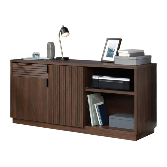
- Page 1 Teknik www.teknikoffice.co.uk Your holder for all things awesome. Elstree Credenza Model 5426916...
- Page 2 Table of Contents Assembly Tools Required Part Identification No. 2 Phillips Screwdriver Tip Shown Actual Size Hardware Identification Assembly Steps 6-29 Français 30-34 Tape Measure Español 35-39 Safety 40-42 Warranty Now you know Part Identification our ABCs. å Use this part identification to help identify the parts. RIGHT END (1) SIDE BASE (2) PRINTER SHELF MOLDING (1)
- Page 3 Part Identification å While not all parts are labeled, some of the parts will have a label or an inked letter on the edge to help distinguish similar parts from each other. Use this part identification to help identify similar parts. D107 D971 D108...
- Page 4 Hardware Identification 40CA CABINET RIGHT - 1 40CB CABINET LEFT - 1 40CC DRAWER RIGHT - 1 40CD DRAWER LEFT - 1 (EXTENSION SET SHOWN SEPARATED) EXTENSION RAIL - 2 EXTENSION SLIDE - 2 10A SLIDE CAM - 2 40MA 40MC HIDDEN CAM - 4 CAM DOWEL - 4...
- Page 5 Hardware Identification å Screws are shown actual size. You may receive extra hardware with your unit. BLACK 9/16" LARGE HEAD SCREW - 50 3S GOLD 5/16" FLAT HEAD SCREW - 12 BLACK 1/2" FLAT HEAD SCREW - 8 30S BLACK 1-9/16" FLAT HEAD SCREW - 4 102S 113S BLACK 1-15/16"...
- Page 6 Hardware Usage Guide HOW TO USE A TWIST-LOCK FASTENER ® Push a TWIST-LOCK® FASTENER 1. Insert the dowel end of the FASTENER into the into the large hole in the part. hole of the adjoining part. NOTE: The dowel end of the FASTENER must remain fully inserted in the hole of the adjoining part while locking the FASTENER.
- Page 7 Step 1 å Assemble your unit on a carpeted floor or on the empty carton to avoid scratching your unit or the floor. Just think. The sooner you do this, the sooner å Push four TWIST-LOCK FASTENERS (36F) into the large you do something else.
- Page 8 Step 2 å Separate the EXTENSION SLIDES (40MC) from the EXTENSION RAILS (40MA) as shown in the upper diagram below. Be prepared, the parts are greasy. å Fasten the EXTENSION RAILS (40MA) to the RIGHT UPRIGHT (D). Use four GOLD 5/16" FLAT HEAD SCREWS (3S) through holes #1 and #3.
- Page 9 Step 3 å Insert two WOOD DOWELS (15F) into the TOP (R) using Caution the exact holes shown. Do not stand the unit upright without the å Fasten the RIGHT END (A) and RIGHT UPRIGHT (D) to BACK fastened. The unit may collapse. the TOP (R).
- Page 10 Step 4 å Slide the BACK (K) into the grooves in the END (A) and Caution the TOP (R). Do not stand the unit upright without the BACK fastened. The unit may collapse. Groove F i n i s h e u r f a Groove Page 10...
- Page 11 Step 5 å Push four TWIST-LOCK FASTENERS (36F) into the large holes in the LEFT END (B) and LEFT UPRIGHT (C). Page 11...
- Page 12 Step 6 å Fasten the CABINET RIGHT (40CA) to the LEFT UPRIGHT (C) and the CABINET LEFT (40CB) to the LEFT END (B). Use four GOLD 5/16" FLAT HEAD SCREWS (3S) through holes #1 and #4. Roller end GOLD 5/16" FLAT HEAD SCREW (4 used for the RAILS) Roller end Groove...
- Page 13 Step 7 å Insert two WOOD DOWELS (15F) into the TOP (R) using the exact holes shown. å Fasten the LEFT END (B) and LEFT UPRIGHT (C) to the TOP (R). Tighten four TWIST-LOCK FASTENERS. å NOTE: Be sure the WOOD DOWELS in the TOP insert into the LEFT END.
- Page 14 Step 8 å Push four HIDDEN CAMS (1F) into the BOTTOM (E). Then, insert the metal end of a CAM DOWEL (2F) into each HIDDEN CAM. Arrow Do not tighten the HIDDEN CAMS in this step. Metal end Arrow Metal end Page 14...
- Page 15 Step 9 å Fasten the BOTTOM (E) to the ENDS (A and B). Tighten four HIDDEN CAMS. å NOTE: You may need to flex the ENDS outward to insert the BOTTOM. å Fasten the BOTTOM (E) to the UPRIGHTS (C and D). Use four (113S).
- Page 16 Step 10 å Fasten four CORNER BRACKETS (31G) to the BOTTOM (E) exactly as shown. Use eight BLACK 9/16" LARGE HEAD SCREWS (1S). BLACK 9/16" LARGE HEAD SCREW (8 used in this step) www.sauder.com/service Page 16...
- Page 17 Step 11 å Fasten ten METAL BRACKETS (4G) to the BASES (F, J, and Q). Use ten BLACK 9/16" LARGE HEAD SCREWS (1S). Now might be a good time to refresh å NOTE: Be sure the BRACKETS are even with the edges of the BASES. your drink.
- Page 18 Step 12 å Fasten the SIDE BASES (F) to the BOTTOM (E). Use two BLACK 9/16" LARGE HEAD SCREWS (1S) through the METAL BRACKETS on the SIDE BASES and into the BOTTOM. å Fasten the SIDE BASES (F) to the CORNER BRACKETS.
- Page 19 Step 13 å Fasten the FRONT BASE (J) and the BACK BASE (Q) to the BOTTOM (E). Use eight BLACK 9/16" LARGE HEAD SCREWS (1S) through the METAL BRACKETS on the FRONT and BACK BASES and into the BOTTOM. å Fasten the FRONT BASE (J) and the BACK BASE (Q) to the CORNER BRACKETS.
- Page 20 Step 14 å Carefully turn your unit onto its front edges. å Fasten twelve BACK CONNECTORS (39F) to the 2" ENDS (A and B), BOTTOM (E), TOP (R), and BACK (K). 3" Tighten the SCREW in each BACK CONNECTOR. Slide the lip into the groove, then tighten the screw.
- Page 21 Step 15 å Fasten two HINGES (14H) to the DOOR (N). Use four BLACK 1/2" FLAT HEAD SCREWS (11S). å Fasten one PULL (189K) to the DOOR (N). Use two BLACK 9/16" LARGE HEAD SCREWS (1S). å Fasten two HINGES (13H) to the LOUVER DOOR (L). Use four BLACK 1/2"...
- Page 22 Step 16 å Carefully stand your unit upright. å Push two DOOR STOPS (4I) into the holes in the Stop LEFT UPRIGHT (C). å Before fastening the DOOR to your unit, be sure the Mounting mounting screw is against the stops as shown in the screw right diagram.
- Page 23 Step 17 å Refer to the enlarged diagram to identify the parts on Mounting screw (depth) the HINGES. Adjusting screw (horizontal) å The DOORS may need some adjustments. Follow the text below to make needed adjustments. å DOOR ADJUSTMENTS: To adjust the DOORS from side to side (horizontal), turn the adjusting screw in or out.
- Page 24 Step 18 å Push two TWIST-LOCK FASTENERS (36F) into the large holes in the PRINTER SHELF (M). å Fasten the PRINTER SHELF MOLDING (P) to the PRINTER SHELF (M). Tighten two TWIST-LOCK FASTENERS. Page 24...
- Page 25 Step 19 å Fasten the EXTENSION SLIDES (40MC) to the PRINTER SHELF (M). Use four SILVER 1" LARGE HEAD If you're doing this to SCREWS (102S) through holes #2 and #4. help a friend, don't leave without a bite. Open end Open end 102S Drawer Slide...
- Page 26 Step 20 The tabs should insert freely With the palm of into the slots. Gently tilt the your hand, tap DRAWER SIDES side to side the DRAWER until the tabs slip into the slots. BOTTOM down into the groove. U n fi n i s h s u r f a c...
- Page 27 Step 21 å Insert a SLIDE CAM (10A) into the DRAWER SIDES (D107 and D108). å Fasten the DRAWER RIGHT (40CC) to the RIGHT DRAWER SIDE (D107) and the DRAWER LEFT (40CD) to the LEFT DRAWER SIDE (D108). Use four GOLD 5/16" FLAT HEAD SCREWS (3S) through holes #1 and #4. å...
- Page 28 Step 22 å Insert the GROMMET (10P) and GROMMET CAP (1P) into the large hole in the BOTTOM (E). å To insert the drawer into your unit, tip the front of the drawer down and drop the glides on the drawer behind the glides on the unit.
- Page 29 Step 23 å NOTE: Before inserting the PRINTER SHELF, be sure the INNER CARTRIDGE in the EXTENSION RAIL on your unit is all the way forward. The INNER CARTRIDGE should click into place against the BLACK TAB. å To insert the PRINTER SHELF into your unit, line up the EXTENSION SLIDES on the PRINTER SHELF with the EXTENSION RAILS on the unit and push the PRINTER SHELF into the unit until the PRINTER SHELF is fully inserted.
- Page 30 Step Step 24 å To make adjustments to the drawer, loosen SCREW #4 in the SLIDES a 1/4 turn, then turn the cam clockwise or counter- clockwise. Notice how the drawer raises or lowers as you turn the cam. By adjusting the drawer this way, it will help the DRAWER FRONT line up better when closed.
- Page 31 WARNING Please use your furniture correctly and safely. Improper use can cause safety hazards, or damage to your furniture or household items. Carefully read the following chart. Look out for: What can happen: How to avoid the problem: • Overloaded shelves or drawers. •...
Need help?
Do you have a question about the Elstree Credenza 5426916 and is the answer not in the manual?
Questions and answers