Table of Contents
Advertisement
Quick Links
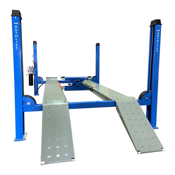
4 POST HOIST
AutoLift 6435W
Model No: SXJS4019A 4 Post Vehicle Hoist
4000Kg Maximum Lifting Capacity
Design Registration Approval Number: WAH20540
Design Code: AS1418.9-1996
Note: While all due care and attention has been taken in the preparation of this document, Advance AutoQuip shall not be liable for any inaccuracies or omissions
INSTALLATION MANUAL & OPERATION
INSTRUCTIONS
- READ THE ENTIRE CONTENTS OF THIS MANUAL BEFORE
INSTALLATION AND OPERATION. BY PROCEEDING YOU AGREE THAT
YOU FULLY UNDERSTAND AND COMPREHEND THE FULL CONTENTS
OF THIS MANUAL. FORWARD THIS MANUAL TO ALL OPERATORS.
FAILURE TO OPERATE THIS EQUIPMENT AS DIRECTED MAY CAUSE
Specifications subject to change without notice.
2 McDonald Crescent | Bassendean WA 6054
Ph: 08 9279 1663 | Fax: 08 9279 1667 | E: sales@aaq.net.au | W: www.aaq.net.au
INJURY OR DEATH.
which may occur therein
Advance AutoQuip
READ FIRST
DO NOT use the
machine until you read
and understand all the
dangers, warnings and
cautions in this manual.
Advertisement
Chapters
Table of Contents

Related Manuals for AAQ SXJS4019A


Summary of Contents for AAQ SXJS4019A
- Page 1 Note: While all due care and attention has been taken in the preparation of this document, Advance AutoQuip shall not be liable for any inaccuracies or omissions which may occur therein Advance AutoQuip 2 McDonald Crescent | Bassendean WA 6054 Ph: 08 9279 1663 | Fax: 08 9279 1667 | E: sales@aaq.net.au | W: www.aaq.net.au...
-
Page 2: Table Of Contents
INSTALLATION INSTRUCTIONS Contents: Ⅰ Statement……………………………………………………2 Ⅱ Installation requires............2-3 2.1 Installation Tools………………………………………2-3 2.2 Installation Site………………………………………..3 2.3 Installation foundation conditions………………………3 III Installation instructions........3-23 3.1 Foundation Drawings……………………………3-4 3.2 Platform and steel rope installation…………………………….5-9 3.3 Post and beam installation………………………………………9-12 3.4 Installation of auxiliary platform……………………………13-16 3.5 Packing disassembly and installation of the post…………17-20 3.6 Connection of steel rope and column………………………20-23 3.7 Vertical adjustment of column required……………………23... -
Page 3: Ⅱ Installation Requires
I. Description: This installation manual is applicable to the installation of all electronically controlled and manual four post lifts. Because the product is constantly updated and improved, this installation instruction may differ slightly from the actual structure of the device, but most of the details are the same. -
Page 4: Installation Site
⑨ ⑩ ⑪ 2.2 Installation Site: Only the personnel designated by the manufacturer or the professional and technical personnel entrusted by the dealer can install this equipment. The installers must have qualifications for practice; non-professional installation may cause serious personal or equipment injury. - Page 5 The foundation drawing is shown in the following figure: SXJS4019/SXJS4019A/SXJS4019B MAX. MIN. FOUNDATION DIMENSIONS QUALITY OF REACTION ON 150mm PRESSURE CONCRETE EACH IN MM...
-
Page 6: Platform And Steel Rope Installation
3.2 Platform and Steel rope installation : 3.2.1 Firstly check the list in the standard box and accessory box to check whether the standard and small parts are missing. If it is found missing, please contact the logistics company or manufacturer immediately; if it is not missing, place it in a safe place that is easily accessible. - Page 7 Main platform Steel Rope in Front position Fig2 Main platform Steel Rope in Front position Fig3 Rear of the platform (where the bridge sleeve of the approach bridge is welded, that is, the driving ramp position) indicates: Main platform Steel Rope in Rear position Fig1...
- Page 8 Main platform Steel Rope in Rear position Fig2 Main platform Steel Rope in Rear position Fig3...
- Page 9 Top view of steel rope general arrangement...
-
Page 10: Post And Beam Installation
SXJS4019/SXJS4019A/SXJS4019B STEEL ROPE LENGTH: 1=9435mm,2=7930mm,3=4765mm,4=3270mm 3.2.4 When the four post lift is assembled and packaged, the connection of the steel rope to the oil cylinder and the installation of the pulley have been completed; therefore, when the equipment is installed, the customer can pass the steel rope... - Page 11 arrow B are the auxiliary platform mounting holes. Four of the holes are also used according to the platform space to install the sub-platform. The specific placement of the beam is shown below: In the figure above, the beams at points A and B are the main beams; the beams at points C and D are the auxiliary beams, where the main pillar is placed at point A and the auxiliary pillars are placed at the remaining points B / C / D;...
- Page 12 Lift the main platform to points A and C, adjust the four holes on the head and tail of the platform to precisely align with the four screw holes on the beam, and fine-adjust if necessary; now screw the bolts into the screw holes, taking care not to tighten; Note that the head of the platform is an M16 * 45 hexagonal bolt with a flat spring washer, and the tail is an M16 * 45 hexagonal screw with a flat spring washer.
- Page 13 Steel Rope Connection diagram-Ramp position Steel Rope Connection diagram-axonometric In the above three pictures, the connection and installation methods of the steel rope to the platform, beams, and columns are schematically illustrated; the serial number ①, ②, ③, and ④ correspond to the length of the steel rope marked by the previous serial number 1/2/3/4.
-
Page 14: Installation Of Auxiliary Platform
3.4、Installation of auxiliary platform Remove the auxiliary platform on the package and turn it over, and lift it to the points B and D of the beam; Note that the installation position of the auxiliary platform is adjustable, and the inner side of the main and auxiliary platform guide rails can be adjusted from 900mm to 1000mm. - Page 15 ITEM SPEC Tubling bracket Tubing compression bracket Hex nuts Upper clamping plate Hex nuts Hexagon socket head cap M4×20 screw...
- Page 16 In the figure above, the hydraulic pipes use the pipe compression bracket and the upper clamping plate, pressed on the carriage by the hexagon socket screws and nuts.The small holes on both sides of the tubing are used as the passage holes for the electric control four-post trolley control wire.
- Page 17 Before installing the carriage reinforcement, you need to install the tubing carriage on the carriage reinforcement, and then fix the ends of the carriage reinforcement with M8 nuts and φ8 flat pads to the welded bracket on the auxiliary platform, and tighten and straighten the carriage reinforcement.
-
Page 18: Packing Disassembly And Installation Of The Post
3.5The diagram after the platform is connected to the beam is shown below:: ITEM SPEC Main beam Auxiliary beam Main platform Auxiliary platform Outer hexagon bolt M16*45 Spring pad φ16 Flat pad φ16 Socket head cap screws M16*45 Note that after the platform and the beam are connected by bolts, do not tighten them in advance. - Page 19 Item Spec Safety lock Move the post into the end of the beam so Mechanical lock that the nylon roller at the end of the beam touches the inside of the post. See below::...
- Page 20 The arrow in the figure shows the nylon limit roller. Install the column top cover. Note that the M20 nuts are installed on both sides of the top cover, not on one side. After the whole assembly, turn the nut on the lower part of the top cover, adjusting the level of the platform loading on the lock.
-
Page 21: Connection Of Steel Rope And Column
The hole for installing the mechanical lock bar on the column top cover is a long round hole to ensure that the lock bar has a certain amount of adjustment in the lateral direction, so that the mechanical lock bar is maintained at the middle position in the end of the beam. - Page 22 in the top cover of the column, and screw in two nuts (supplied with the rope); Note that there are two rope installation holes on the column top cover. According to the position of the large pulley installed on the beam, pass the rope through the corresponding holes.
- Page 23 The schematic diagram of the steel rope installed on the column top cover is as follows: Note: The two nuts of the steel rope must be installed above the column top cover, as shown in Figure A above. There are two holes for installing the steel rope on the...
-
Page 24: Vertical Adjustment Of Column Required
column top cover, and the steel rope needs to be selected to pass through the corresponding hole. 3.7 Vertical adjustment of column required: Use a spirit level to adjust the verticality of the column. The angle of the column should be less than 1 ° (in the direction indicated by the arrow in the figure below) so that the lift can offset the elastic deformation that occurs when the load is lifted. - Page 25 Name Spec. Qty. Electric control box M8*12 Socket head cap M6*25 screws Socket head cap M6*10 screws Pneumatic release solenoid valve Flange nut Flange face hex head M8*30 bolts Pump station Air source processing Optional system 1.2 Installation of upper and lower limit switches: ( Note:Lower limit switch is optional)...
- Page 26 Pass the wires of limit switches into corresponding holes of main column ,and pass through the wires protection slot,collect them into the holes under the electric control box,and then pull them out.Connect the corresponding terminal according to the wiring diagram.After fixing limit switches to the bracket with 2 pieces of M5 * 8 hexagon socket screws, then fix the limit switch bracket to the main column with M6 * 8 hexagon socket screws.Then tighten the screws after adjusting the positions of the limit switch bracket in the testing.
- Page 27 The arrow refers in the left figure is tensioner. After all the wires pass through the tensioner,tighten the nut to prevent the wiring in the electric control box from loosening and falling off. 2 Electrical wiring instructions:the schematic and wiring diagram is only applicable to the electrical four post lift.
- Page 28 The electrical schematic and wiring diagram of standard electrical four post lift as above figures.
- Page 29 The electrical schematic and wiring diagrams of adding the upper and lower limits and the wire rope anti-break limit as above figures. 2.2 Steel rope anti-break limit switch adjustment diagram: The angle between the swing lever of the limit switch and the center line of the switch is about 14 °, and the extended length of the swing lever is about 68 mm;...
- Page 30 dimensions have been adjusted well before ex-factory; due to the manufacturing and installation errors , users may need to minute adjustment on-site. 3. Schematic diagram of pneumatic unlocking tube arrangement: Arrange the air tube of the corresponding length according to the schematic diagram for installation.
- Page 31 The above figure is the schematic diagram of the oil tube connection.The XXX represents the oil tube length of the trolley is 7100mm for 4tons four post lift such as SXJS4019/SXJS4019B Main platform connect with motor P1,oil pipe length 2000mm,connect with big cylinder 1600mm oil pipe .
- Page 32 2.Connect the oil pipe conversion bracket, as shown below: Inner haxagon bolt M8×16 Flat washer φ8 Oil pipe conversion bracket Hexagon lock screw Inner hexagon bolt M6×16 Pipe clip 5T slider cambination 9 Slider combination...
- Page 33 In the figure above, the pipe conversion bracket with the number 3 is fixed to the jacking beam puller with the M8 × 16 hexagon socket screws with the number 1 and the φ8 flat washer with the number 2. The connecting plate of the tubing conversion bracket has a long slot.
- Page 34 Name Specification Main post Vice post Beam Beam Main platform Vice platform Ramp Jacking beam VI.、Adjustment 1. After confirm that the circuit, air and oil connections are correct, inject hydraulic oil in the motor, and the oil volume should not be less than 10L. After connect with air and power supply,press up button, pay attention to the direction of the motor.
- Page 35 the up button time too long, the gear pump will be damaged; Observe whether there are any abnormalities such as blockage and abnormal noise or odor in each part of the lift. 2. After completing the above simple inspection, raise the lift to a height of about 1 meter, press the lock button or pressure relief handle to make the mechanical lock fully work, and check whether the mechanical lock of each column can work safely and reliably;...
- Page 36 OPERATION INSTRUCTIONS Contents Chapter 1 General………………………………………………………………………………6-8 1.1 Summary…………………………..……………………………………………………6 1.2 Technical performance parameters and overall dimensions drawing……………………6-7 1.3 Operating principle………………………………………………………………………7 1.4 Structure performance……………………………………………………………………8 Chapter 2 Safety Instructions……………………………………………………………………9-13 2.1 Safety rules………………………………………………………………………………9 2.2 Warning mark……………………………………………………………………………9-11 2.3 Machine nameplate………………………………………………………………………11 2.4 Safety design introduction………………………………………………………………11-13 Chapter 3 Installation…………….……………………………………………………………13-20 3.1 Installation conditions and environment………………………….……………………13 3.2 Loading and unloading, transportation and storage…………………………………….13 3.3 Handling safety events and method……………………………………………………13...
- Page 37 4.2 Precautions………………………..……..…………………………………………21 4.3 Work panel instructions……………………………………………………………22 4.4 Operating instruction of four-wheel alignment slip plate/turntable………………..23 4.5 Introduction of four-post alignment principle……………………………..………23 Chapter 5 Maintenance…………………………………………………………………..…23-25 5.1 Maintenance……………………………………………….……………………..…23-24 5.2 Common failure and troubleshooting…………………………………………….…24 5.3 List of wearing parts …………………………………………………………………25 Chapter 6 Electrical Safety…………………………………………………………………25-27 6.1 Electrical control system safety rules………………………………………………..25 6.2 Circuit diagram………………………………………………………………………25-26 6.3 List of electrical components…………………………………………………………26-27...
- Page 38 Special Notes Notes For any damage occurring to the equipment during loading and transportation, the buyer should lodge a claim against the carrier. During design and manufacture, we have taken full consideration of the safety performance of the lift. Only with sufficient training and skillful operation can the safety of the product be assured.
-
Page 39: Chapter 1 General
Chapter 1 General 1.1 Summary Performance and features A. Integrating with functions of inspection, maintenance and four-wheel alignment, beautiful in appearance. B. Hydraulic cylinder drive, steel rope transmission, quiet working environment. C. The mechanical safety lock can be locked at proper height as required for operation, which is safe and reliable. -
Page 40: Operating Principle
1.2.1 Overall dimensions 1.3 Operating principle The four-post lift is a lift which is of mechanical structure, utilizes hydraulic pressure to generate power, and mechanically controls to lock and pneumatically looses executive components. 1.4 Structure performance 1.4.1 Structure performance The lift is a common four-post hydraulic type. The service conditions of most users are taken into consideration in structure design. - Page 41 1.4.2 Power unit The hydraulic system is of hydraulic power unit and it has the function of manually adjusting pressure. By rotating the adjusting screw of the overflow valve, the system pressure can be adjusted; it also has the function of manually adjusting lowering speed. By rotating the adjusting screw of check valve, the lowering speed of platform and cart can be adjusted.
-
Page 42: Chapter 2 Safety Instructions
Chapter 2 Safety Instructions 2.1 Safety rules Please read and fully understand the entire contents of this manual prior to operation, such as instructions and rules. Negligence may cause severe accidents, electric shock or serious physical injury and property damage. a. -
Page 43: Warning Mark
2.2 Warning mark... -
Page 44: Safety Design Introduction
2.3 Machine Label Model: SXJS4019 Date: Lifting height: 1900mm Serial No.: SZL Power: 380V/50Hz/2.2Kw Rated load: 4000Kg Full load current: 10A Machine dimensions: 6058*3019*2370 Machine weight: 1200Kg Hydraulic pressure:18MPa 2.4 Safe design introduction 2.4.1 Steel rope break-proof mechanism (see the picture) Operating principle: Under the locking circumstance of the platform, the steel rope is loose and the safety hook is in reset condition under double spring tension;... -
Page 45: Chapter 3 Installation
Cylinder explosion-proof valve (see the picture for structure ) Operating principle: The cylinder explosion-proof valve is placed at the oil inlet of the cylinder. It will be prevent the dangerous of the platform dropping to fast when the oil pice suddenly broken. Chapter 3 Installation 3.1 Installation conditions and environment a. -
Page 46: Select Installation Location
damaging personnel or equipment. b. During lifting, please find the center of gravity and lift evenly. If uneven in front and rear, right and left, it is not allowed to lift the equipment in order to prevent it from turning aside and causing damage to personnel or equipment. -
Page 47: Installation And Commissioning
3.6 Installation and commissioning A. Before installing the lift, pay attention to following events: a) The location of the lift should be subject to the design and planning requirements of the whole site. Try to leave enough operation space as much as possible. b) The steel reinforced concrete should be poured after compaction of the groundwork. - Page 48 a) The side without welding nut on the H steel of the lifting beam should be outwards. b) The end with hole (on center façade of H beam) of the lifting beam is located at one side of the primary platform (installed with hydraulic cylinder). c) Before placing beam, dismount the gusset plate and place the steel ropes on the primary platform according to the direction respectively (refer to Fig.
- Page 49 prepared for adjustment of installation later. D. Installation of hydraulic pumping station: Install the hydraulic pumping station on the upright post welded with soleplate and fix by screw. Connect hydraulic oil pipes with the primary platform and joints of cart hydraulic cylinder respectively and tighten the nut on the joints connected with the primary platform.
- Page 50 d) Align the hole of post soleplate with the hole on the floor, insert the expansion bolt and assembly the nut and washer onto the bolt, leaving screw thread of 3~5mm. Then use a hammer to strike the spindle of the expansion bolt until the washer and the soleplate of the post are in close contact.
-
Page 51: Chapter 4 Operation
Chapter 4 Operation 4.1 Preparation before commissioning a. Coat the lithium grease (GB7324-87) on the movable contact surface of the beam and it needs to coat all the surfaces evenly from top to bottom. b. Fill the hydraulic pumping station full of hydraulic oil N46 (SY1227-84). As the temperature is low in winter, the high pressure anti-wear hydraulic oil of above 32# and lower than 40# can be selected. -
Page 52: Chapter 5 Maintenance
There are three movable blocks at the front side of four-post lifting platform. To carry out four-wheel alignment, take off the movable block of 540mm long and put the turntable here. According to the length of the vehicle body, adjust the position of other two movable blocks. Next, adjust the position of the turntable to make the central vertical line of the front wheel coincide with the center of turntable. -
Page 53: Common Failure And Troubleshooting
5.2 Common failure and troubleshooting Failure Troubleshooting method Check whether there is power; Motor not work; Check whether the wiring in the terminal box of the motor is loose; Motor is not forceful; Phase-failure of the motor; Reverse the motor and check three-phase four-wire power;... -
Page 54: Chapter 6 Electrical Safety
Chapter 6 Electrical Safety 6.1 Electrical control system safety rules A. Only formally trained personnel and those with professional knowledge can carry out electrical maintenance and troubleshooting. B. Do not alter or omit protective interlocks. C. Please read carefully and pay attention to the warning marks before startup. D. -
Page 56: Chapter 7 Pneumatic 、Hydraulic System
Chapter 7 Hydraulic System 7.1 Hydraulic pressure principle drawing... - Page 57 Inspection Report Product name: Four-post Lift Product model: SXJS4019 The executive standard of the product is Q/0601KHD002-2013. Before ex-work, the inspection items and results of the product are as follows: Standard value Measured value Inspection items Unit Mainframe Mainframe Lifting height 1900 Lifting capacity 4000...
- Page 58 Packing List Name Quantity Remark Model & Specifications Upright post 4 pcs 4 pcs/set 330x200x2265mm Beam 2 pcs 2945×115x310mm Including cylinder, oil pipe, steel rope Primary platform 1 pcs 4564×554×172mm Secondary platform 1 pcs 4564×554×172mm Large ramp 2 pcs 1280×490×170mm Front baffle plate 2 pcs 498x35x153mm...
- Page 59 Packing List of Standard Parts Model & Name Quantity Remark Specifications M16x140 Expansion bolt 16 sets The anchor bolt has nut, flat washer, spring washer. The pumping station seat has nut, double plat washers Outside hexagon bolt M8x25 4 sets and spring washer.
- Page 66 Code Name Spec Note 91020110 Main column 91020110 Top cover 12030100 Hex nut M12×30 12050201 Flat washer φ12 12050203 Elastic washer φ12 12010101 Hax nut 91020110 Lift bar 12010101 Hex nut 12020301 Hexagon socket head cap screw M10×25 91020110 Manual air valve mounting bracket 12020301 Hexagon socket head cap screw...
- Page 67 12020301 Hexagon socket head cap screw M5×8 91020120 Slave column 91020130 another one code is Beam 91020140100 91020131 Big pulley 13010100 self lubricate bearing 323633 91020131 platform pulley washer 1.5 91020131 beam pulley shaft 91020131 beam pulley shaft fixing plate 12020301 inner hex screw M8×12...
- Page 68 91020131 spring rod 91020132 spring 12010500 hex nut 91020130 spring-symmetrical 12020101 cross head screw M6×12 91020130 spring fixing bolt 91020530 spring-symmetrical 13030000 flexible bearing SI8TK 12030100 Hex head bolt full thread M8×35 14010100 MA-20-25- cylinder 91020230 Cylinder mounting shaft 91020130 Torsion spring 91020530 Torsion spring-EAGLE...
- Page 69 13020100 Deep groove ball bearing 6003-2Z 91020151 Bearing spacer 12060100 side sliper plate tension spring 91020150 side sliper plate 91020152 Tubing cover 12020301 Hexagon socket head cap screw M6×10 91020151 front block 12020301 Hexagon socket head cap screw M12×20 91020150 Platform pulley spacer 35 91020152 Wire rope anti-offset angle...
- Page 70 91020151 steel rope fix board bracket 91020152 steel rope fix board bracket-symmetry 91020151 ramp lock pin 12090100 shaft circlip φ17 91020150 platform pulley shaft 1 91020150 platform pulley shaft 2 91020150 platform pulley shaft 3 91020160 vice platform 91020170 ramp 91020170 nylon roller 12090100...
- Page 71 4000 4 TONNE 4 Post Hoist OPERATING INSTRUCTIONS The hoist should only be operated by personnel that have been OPERATING INSTRUCTIONS thoroughly trained in operation and maintenance of the hoist. The lift should only be operated by trained personnel that have been thoroughly trained in operation and maintenance of the lift.
- Page 72 SAFETY OPERATING PROCEDURES Vehicle Hoist DO NOT use this machine unless the operator has been thoroughly instructed in its safe use and operation. Safety glasses must be worn at all Long and loose hair must be times in work areas. contained.
- Page 73 COMMISSIONING REPORT 1. Details of Customer Customer Name: Installation Address: 2. Hoist Details Model No: 2 McDonald Crescent Hoist Type: Bassendean WA 6054 Installation Date: P: 08 9279 1663 | E: sales@aaq.net.au 3. Commissioning Report Comments Safety Devices Safety devices incorporated into the design of the vehicle to AS/NZS 1418.9 Welds Visual check all welds completed and comply to requirement of AS/NZS 1554 Hydraulic Equipment and Controls Visual check carried out for leaks Pneumatic Equipment and Controls Visual check carried out for leaks Safety Locks Safety locks tested for correct operation Support Pads Checked for good working order Wheel Stops Supplied with the hoist and in good working order Hoist Motion Limits Checked for correct operation Load Test and Speed Check Hoist checked with load for correct operation and speed control tested Wire Ropes Checked wire ropes for correct installation and tension Concrete Floor Concrete floor is a suitable depth for installation...
- Page 74 COMMISSIONING REPORT Location of Vehicle Hoist & Vehicle Clearances Vehicle hoist or any part of the load is positioned no less than 600mm away from any fixed structure Provisions have been made for effective clearances above the vehicle when the hoist is in its fully raised position. Markings ‐ Hoist Checked for Relevant Marking Including: Make & Model Number Serial number Rated Capacity Reference to maintenance Operation instructions Screw and Nut Gaps Hoist compliance plate showing design registration Functional Test Vehicle hoist has been tested and all safety devices, limit switches and control function interlocks have been tested for correct operation. Demonstration The installer has demonstrated the operation of the vehicle hoist to the owner or operator Electrical Equipment and Controls Lock off isolating switch installed Emergency stop button installed 3. Details of Electrical Contractor Trading Name: EC Licence Number: Address: Telephone Number: 4. Signature Name: ___________________________________________________________ Date: I, being the person responsible for completing the commissioning report have exercised reasonable skill and competency when completing the report and herby certify that the vehicle hoist has been commissioned fit for use as per the Australian / New Zealand Standard 1418.9:1996 Vehicle Hoists.
Need help?
Do you have a question about the SXJS4019A and is the answer not in the manual?
Questions and answers