Icom VHF IC-FR5000 Insrtuction Manual
Vhf fm repeater and uhf fm repeater
Hide thumbs
Also See for VHF IC-FR5000:
- Service manual addendum (181 pages) ,
- Service manual (44 pages) ,
- Instruction manual (16 pages)
Table of Contents
Advertisement
Quick Links
Advertisement
Table of Contents

Subscribe to Our Youtube Channel
Related Manuals for Icom VHF IC-FR5000


Summary of Contents for Icom VHF IC-FR5000
- Page 1 INSTRUCTION MANUAL VHF FM REPEATER iFR5000 UHF FM REPEATER iFR6000...
-
Page 2: Explicit Definitions
DO NOT put anything on top of the repeater. This will obstruct heat dissipation. Icom, Icom Inc. and the Icom logo are registered trademarks of Icom Incorporated (Japan) in the United States, the United Kingdom, Germany, France, Spain, Russia and/or other... -
Page 3: Safety Training Information
“PTT” switch. Electromagnetic Interference/Compatibility During transmissions, your Icom radio generates RF energy that can possibly cause interference with other devices or systems. To avoid such interference, turn off the radio in areas where signs are posted to do so. -
Page 4: Forward
Thank you for purchasing this Icom repeater. The The following accessories are supplied. IC-FR5000/IC-FR6000 is de- uhf fm repeaters signed and built with Icom’s state of the art technol- Handles For handles attachment ogy and craftsmanship. With proper care, this product Spacers should provide you with years of trouble-free opera- tion. -
Page 5: Table Of Contents
TABLE OF CONTENTS 3 OPERATION ..........7 IMPORTANT ............... i EXPLICIT DEFINITIONS ..........i n Receiving and transmitting ........ 7 PRECAUTIONS ............i D Repeater operation ........7 SAFETY TRAINING INFORMATION ......ii D Base station operation ........7 FOR CLASS B UNINTENTIONAL RADIATORS ..ii 4 MAINTENANCE .......... -
Page 6: Panel Description
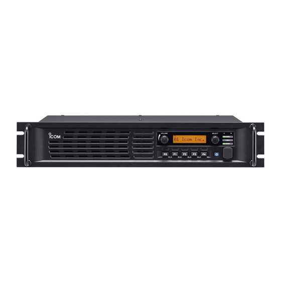
PANEL DESCRIPTION n Front panel Function display q INTERNAL SPEAKER u MICROPHONE CONNECTOR [MIC] Monitors received signals. This 8-pin modular jack accepts the optional micro- phone. w VOLUME CONTROL [VOLUME] (p. 7) KEEP the [MIC] connector cover attached to the Adjusts the audio output level. -
Page 7: D Function Display
PANEL DESCRIPTION D Function display I C O M I n c . q SIGNAL STRENGTH INDICATOR r COMPANDER INDICATOR Indicates relative signal strength level. Appears when the compander function is activated. w LOW POWER INDICATOR t SCRAMBLER/ENCRYPTION INDICATOR Appears when low output power is selected. Appears when the voice scrambler/encryption function is activated. -
Page 8: D Accessory Connector
PANEL DESCRIPTION D Accessory connector Pin No. Pin Name Description Specification No connection — Output terminal for serial communication data. — Input terminal for serial communication data. — Output terminal for request-to-send data. — Input terminal for clear-to-send data. — No connection —... -
Page 9: Installation And Connections
INSTALLATION AND CONNECTIONS n Unpacking n Antenna connection After unpacking, immediately report any damage to For radio communications, the antenna is a critical the delivering carrier or dealer. Keep the shipping car- component, along with output power and sensitivity. tons. Select antenna(s), such as a well-matched 50 ˘... -
Page 10: Front Panel Connection
Input port for PC programming CAUTION: DO NOT short pin 1 to ground as this can damage the internal 8 V regulator. DC voltage is applied to pin 1 for microphone operation. Only Icom micro- phones are recommended. n Rear panel connection SP-22 EXTERNAL SPEAKER ACC CONNECTOR (p. -
Page 11: Power Supply Connection
INSTALLATION AND CONNECTIONS n Power supply connection n Mounting the repeater D Using the supplied handle Make sure the repeater’s power is turned OFF when connecting a DC power cable. The supplied handles are available for mounting the repeater into a 19 inch rack. The handles can be in- CAUTION: Voltages greater than 16 V DC will dam- stalled to the repeater’s front panel. -
Page 12: Operation
OPERATION n Receiving and transmitting D Base station operation D Repeater operation Receiving Ask your dealer for details of the repeater’s program- q Push [POWER] to turn the power ON. ming. w Set the audio and squelch levels. ➥ Rotate [SELECT]* fully counterclockwise in ad- ➥... -
Page 13: Maintenance
If you are unable to locate the cause of a problem or The following chart is designed to help correct prob- solve it through the use of this chart, contact the near- lems which are not equipment malfunctions. est Icom Dealer or Service Center. PROBLEM POSSIBLE CAUSE SOLUTION REF. -
Page 14: Options
OPTIONS • SP-22 external speaker Compact and easy-to-install. Input impedance : 4 ˘ Max. input power : 5 W • HM-152 hand microphone • SM-25 desktop microphone • UR-FR5000/UR-FR6000 channel extension modules • UC-FR5000 trunking network controller • UT-109R voice scrambler unit Non-rolling type (max. -
Page 15: About Voice Coding Technology
ABOUT VOICE CODING TECHNOLOGY The AMBE+2™ voice coding Technology embodied in this product is protected by intellectual property rights including patent rights, copyrights and trade secrets of Digital Voice Systems, Inc. This voice coding Technology is licensed solely for use within this Communications Equipment. The user of this Technology is explicitly prohibited from attempt- ing to extract, remove, decompile, reverse engineer, or disassemble the Object Code, or in any other way convert... - Page 16 A-6635H-1EX-r Printed in Japan © 2007–2008 Icom Inc. 1-1-32 Kamiminami, Hirano-ku, Osaka 547-0003, Japan Printed on recycle paper with soy ink.
Need help?
Do you have a question about the VHF IC-FR5000 and is the answer not in the manual?
Questions and answers