Table of Contents
Advertisement
Advertisement
Chapters
Table of Contents

Related Manuals for Omron SmartSlice GRT1-OD4G-1


Summary of Contents for Omron SmartSlice GRT1-OD4G-1
- Page 1 Cat. No. W455-E1-08 SmartSlice GRT1 Series Slice I/O Units OPERATION MANUAL...
- Page 2 No patent liability is assumed with respect to the use of the information contained herein. Moreover, because OMRON is constantly striving to improve its high-quality products, the information contained in this manual is subject to change without notice. Every precaution has been taken in the preparation of this manual. Neverthe- less, OMRON assumes no responsibility for errors or omissions.
- Page 3 SmartSlice GRT1 Series Slice I/O Units Operation Manual Revised December 2018...
- Page 5 OMRON Product References All OMRON products are capitalized in this manual. The word “Unit” is also capitalized when it refers to an OMRON product, regardless of whether or not it appears in the proper name of the product.
- Page 7 TABLE OF CONTENTS PRECAUTIONS ........xiii Intended Audience .
- Page 8 TABLE OF CONTENTS SECTION 6 Temperature Input Units ......155 Overview of the Temperature Input Units ........Status Areas .
- Page 9 About this Manual: This manual describes the installation and operation of the Slice I/O Units and includes the sections described below. Please read this manual carefully and be sure you understand the information pro- vided before attempting to install or operate Slice I/O Units. Be sure to read the precautions pro- vided in the following section.
- Page 10 Section 7 provides information required to operate Counter Units and Positioning Units, including functions, status areas, windows, specifications, wiring, I/O data assignments, and settings. Section 8 provides the basic specifications and shows the components, wiring diagrams, and dimen- sions for the other Units used in Slice I/O Terminals. Section 9 describes error processing and troubleshooting procedures needed to keep the Slice I/O Units operating properly.
- Page 11 Products were properly handled, stored, installed and maintained and not subject to contamination, abuse, misuse or inappropriate modification. Return of any Products by Buyer must be approved in writing by Omron before ship- ment. Omron Companies shall not be liable for the suitability or unsuitability or...
- Page 12 Data presented in Omron Company websites, catalogs and other materials is provided as a guide for the user in determining suitability and does not consti- tute a warranty. It may represent the result of Omron’s test conditions, and the user must correlate it to actual application requirements. Actual performance is subject to the Omron’s Warranty and Limitations of Liability.
-
Page 13: Table Of Contents
PRECAUTIONS This section provides general precautions for installing and using the GRT1-series Slice I/O Units and related devices. The information contained in this section is important for the safe and reliable application of the Slice I/O Units. You must read this section and understand the information contained before attempting to set up or operate a Slice I/O Terminal. -
Page 14: Intended Audience
It is extremely important that a PLC and all PLC Units be used for the speci- fied purpose and under the specified conditions, especially in applications that can directly or indirectly affect human life. You must consult with your OMRON representative before applying a PLC system to the above men- tioned applications. Safety Precautions... -
Page 15: Operating Environment Precautions
Operating Environment Precautions !WARNING Provide safety measures in external circuits (i.e., not in the Programmable Controller), including the following items, to ensure safety in the system if an abnormality occurs due to malfunction of the PLC or another external factor affecting the PLC operation. -
Page 16: Application Precautions
Application Precautions • Locations subject to condensation as the result of severe changes in tem- perature. • Locations subject to corrosive or flammable gases. • Locations subject to dust (especially iron dust) or salts. • Locations subject to water, oil, or chemicals (Digital I/O Units) •... - Page 17 Application Precautions • Be sure that all the terminal screws are tightened to the torque specified in the relevant manuals. Loose screws may cause fire, malfunction, or damage the Unit. • Be sure that all the mounting screws and cable connector screws are tightened to the torque specified in the relevant manuals.
-
Page 18: Ec Directives
EMC Directive OMRON devices that comply with EC Directives also conform to the related EMC standards, so that they can more easily be built in to other devices or the overall machine. The actual products have been checked for conformity to EMC standards. - Page 19 EC Directives Ferrite Core (Data Line Filter): 0443-164151 (manufactured by Nisshin Electric) Impedance specifications 25 MHz: 156 Ω 100 MHz: 250 Ω 30 mm 33 mm 13 mm 29 mm 2. Wire the control panel with as thick and short cables as possible and ground to 100 Ω...
- Page 20 EC Directives...
- Page 21 SECTION 1 Available Units and Features This section describes the features of GRT1-series Slice I/O Units and lists the available Units. Slice I/O Terminal Introduction ........1-1-1 Features of the GRT1-series Slice I/O Units .
-
Page 22: Slice I/O Terminal Introduction
Section 1-1 Slice I/O Terminal Introduction Slice I/O Terminal Introduction A Slice I/O Terminal is a building-block style remote I/O terminal made up of a Communications Unit and a number of Slice I/O Units, which each provide a small number of I/O points. The Slice I/O Units communicate with the host by remote I/O communications (cyclic communications) through the Communica- tions Unit. - Page 23 Section 1-1 Slice I/O Terminal Introduction Parameter Backup and Before replacing a Slice I/O Unit for maintenance, the parameter data set in Restore the I/O Unit can be backed up in the connected Communications Unit. The backed up parameter data is compared with the replacement I/O Unit’s data and the backed up data is restored to the replacement I/O Unit.
- Page 24 Section 1-1 Slice I/O Terminal Introduction Contact Operation This function can count the number of times each input or output contact Counter changes from OFF to ON (maximum resolution: 50 Hz). A warning set value can be set in the Unit to monitor the number of contact operations, and turn ON a warning flag in the Status Area when the set value is reached.
- Page 25 Section 1-1 Slice I/O Terminal Introduction The status can be checked at the Master using the Off-wire Detection Flag. This function is valid only for the input ranges 4 to 20 mA and 1 to 5 V. User Adjustment Input or output values can be adjusted to compensate for errors in the input or output voltage or current resulting from the characteristics or connection methods of the I/O device.
- Page 26 Section 1-1 Slice I/O Terminal Introduction Temperature Zone The temperature zone counter can be used to measure how long the temper- Counter ature input value is within a user-set temperature range in 1-second incre- ments. The host will be notified with a flag when the measured value exceeds the set value.
-
Page 27: Available Units
Section 1-2 Available Units Available Units The following tables list the available GRT1-series Units, categorized by type. 1-2-1 Communications Units Type I/O points Model number Description DeviceNet Communications GRT1-DRT Interface Unit that con- Unit nects the DeviceNet Unit with the Slice I/O Units PROFIBUS Communica- GRT1-PRT... -
Page 28: Counter Units And Positioning Unit
Section 1-2 Available Units 1-2-4 Counter Units and Positioning Unit Type Model number Description Counter • A and B counter inputs GRT1-CT1 1 counter Units • One input settable to Z counter Max. frequency: input or digital input 60 kHz (depend- ing on counter •... -
Page 29: Connecting Cable
Section 1-2 Available Units 1-2-6 Connecting Cable Type I/O points Model number Description Turnback Cable for GCN2-100 This is a special turnback cable. Slice I/O Units (1 m) Up to 2 Turnback Cables (2 m total) can be connected for one Communications Unit. -
Page 30: Slice I/O Unit Installation And Power Supply Methods
Section 1-2 Available Units 1-2-8 Slice I/O Unit Installation and Power Supply Methods The following installation and power supply methods apply to all GRT1-series Units. I/O Unit connection Unit I/O connection Unit power supply to I/O power supply installation base block Building-block connections DIN Track Screwless clamp-... - Page 31 SECTION 2 Shared Specifications and Functions This section describes the specifications and functions that are shared by all of the Slice I/O Units. Specifications Shared by the Units ....... . . 2-1-1 General Specifications .
-
Page 32: Specifications Shared By The Units
Section 2-1 Specifications Shared by the Units Specifications Shared by the Units 2-1-1 General Specifications Item Specification ° Ambient operating temperature −10 to 55 C (with no icing or condensation) Ambient operating humidity 25% to 85% Ambient storage temperature ° −25 to 65 C (with no icing or condensation) Noise immunity... -
Page 33: Unit Numbers And I/O Allocations
Section 2-2 Unit Numbers and I/O Allocations The TS indicator shows the status of the Slice I/O Unit itself and the I/O indi- cators show the status of the connected devices. Name Color Status Meaning Green Normal status Normal Unit status Normal network status Flashing Operating The automatic restore/backup... -
Page 34: I/O Allocations In The Slice I/O Terminal's Master Unit
Section 2-2 Unit Numbers and I/O Allocations The Slice I/O Units' unit numbers are allocated automatically in order, from left to right. Communications Unit Note The unit numbers allocated automatically to the Slice I/O Units are unrelated to the DeviceNet node address set with the rotary switches. 2-2-2 I/O Allocations in the Slice I/O Terminal’s Master Unit The Slice I/O Terminal’s I/O data is allocated in the CPU Unit’s I/O memory... - Page 35 Section 2-2 Unit Numbers and I/O Allocations I/O Allocation I/O data is allocated to the I/O Units in the order that they are connected to the Example Communications Unit, regardless of the I/O Units’ models. Unless special allocation data settings are selected with the Communications Unit’s Pro- gramming Device, data is allocated from the first word starting with the Com- munications Unit’s Status Flags and then the leftmost I/O Unit’s data.
- Page 36 Section 2-2 Unit Numbers and I/O Allocations Note As shown in example 1, 0 is entered into any unused area that creates a gap in another area. Such an area cannot be used for any other purpose. If there is more than 1 byte that do not create a gap in any other area, such as in word 4 in example 2, then they can be used for other purposes.
-
Page 37: Functions Shared By All Units
Section 2-3 Functions Shared by all Units Input Data Patterns and Sizes Allocated data pattern Description 1. Input data + Communications Used input data size + 1 word Unit Status Flags Maximum Input Area: 65 words (with Communica- tions Unit) 2. -
Page 38: Automatic Restore Function
Section 2-3 Functions Shared by all Units 2. Turn DIP switch pin 4 (BACK) ON, then OFF, and then ON again within 3 s to start the back up. 3. While the data is being backed up, the DeviceNet Communications Unit’s TS indicator will flash green every 0.5 s. -
Page 39: Online Replacement Function
Section 2-3 Functions Shared by all Units 5. When the power is turned ON again, the Communications Unit will auto- matically detect the Unit that was replaced and download the backup data. The I/O Unit’s TS indicator will indicate the results of the restore operation. •... -
Page 40: Unit Conduction Time Monitor
Section 2-3 Functions Shared by all Units 4. Mount the terminal block that was removed in step 2 and latch the hook that was released. 5. Turn ON the I/O power supply. !WARNING Always turn OFF the I/O Unit's I/O power supply before performing online replacement. - Page 41 Section 2-3 Functions Shared by all Units • Measuring unit: 0.1 hr Host Master Communications Slice I/O Unit Unit Recorded in Unit Corresponding bit turned ON when monitor value is Corresponding bit is turned exceeded. ON in the Communications Unit's status flags. Total ON time Internal circuit power...
- Page 42 Section 2-3 Functions Shared by all Units 2. Click the I/O Module Tab. 3. Click the Edit Button to display the Edit Unit Parameters Window. 4. Input the desired monitor value in the Unit Conduction Time Field. 5. Click the Download Button, and then click the Reset Button to reset the Unit.
-
Page 43: Unit Comments
Section 2-3 Functions Shared by all Units 2-3-5 Unit Comments Function Overview The user can assign and record a name or comment for every Unit (up to 32 characters). The network Programming Device can be used to read and write these Unit names (comments). -
Page 44: I/O Comments
Section 2-3 Functions Shared by all Units 3. Click the Edit Button to display the Edit Unit Parameters Window. 4. Input the desired name in the Comment Field. 5. Click the Download Button, and then click the Reset Button to reset the Unit. - Page 45 Section 2-3 Functions Shared by all Units Setting with a This example shows how to use the DeviceNet Configurator (version 2.43 or Programming Device higher) to set the device comments. 1. Open the Network Configuration Window and double-click the desired 1,2,3...
-
Page 46: Communications Error History Monitor
Section 2-3 Functions Shared by all Units 2-3-7 Communications Error History Monitor Function Overview Information on communications error (communications error code, communi- cations power voltage when the error occurred) for the last four communica- tions errors can be recorded in the Unit. The network Programming Device can be used to read that communications error history. - Page 47 Section 2-3 Functions Shared by all Units 2. Select the desired Slice I/O Unit from the list on the I/O Module Tab Page and click the View Button. 3. Select the Error History Tab in the Maintenance Information Window. The communications error history for the last four errors will be displayed, as shown in the following window.
-
Page 48: Last Maintenance Date
Section 2-3 Functions Shared by all Units 2-3-8 Last Maintenance Date Function Overview This function can be used to write the date on which maintenance was last performed to the Unit. This means that the timing for future maintenance can be judged more easily. - Page 49 SECTION 3 Installation and Wiring This section provides information on installing and wiring the Slice I/O Units. Installation........... . 3-1-1 Connecting the Communications Unit and Slice I/O Units .
-
Page 50: Installation
Section 3-1 Installation Installation The Slice I/O Terminal is installed and set up as a network Slave. The Com- munications Unit’s communications connector connects to the Master Unit through a communications cable. Up to 64 Slice I/O Units can be connected to one Communications Unit. Master Slide Slice I/O Units in from the front to install. -
Page 51: Connecting Additional Slice I/O Units
Section 3-1 Installation 3-1-2 Connecting Additional Slice I/O Units Connect additional Slice I/O Units by aligning the sides of the Units and slid- ing in the next Unit from the front. Up to 64 Slice I/O Units can be connected to one Communications Unit. -
Page 52: Installation On A Din Track
Section 3-1 Installation Connecting the End A GRT1-END End Unit must be connected to the end of the Slice I/O Termi- Unit nal. GRT1-END End Unit Note When connecting Units, always align the guide tracks on the top and bottom of the Units and be sure that they join properly as you slide the Unit toward the DIN Track. - Page 53 Section 3-1 Installation Slice I/O Terminal There is no particular restriction on the Slice I/O Terminal’s orientation. The Orientation Terminal can be mounted in any of the following 6 directions. Installing a Unit Press the Units onto the DIN Track firmly from the front. Press the Unit firmly until it clicks, indicating that the Unit’s DIN Track Mounting Hooks have locked onto the DIN Track.
- Page 54 Section 3-1 Installation Base Block This is the bus section of the Slice I/O Unit. If the main block is damaged or needs to be replaced for any other reason, the base block can be left connected to the Slice I/O Terminal so that the main block can be replaced online.
- Page 55 Section 3-1 Installation Removing an Entire Unit Including the Base Block 1. Remove the main block of the Unit on the right side of the Slice I/O Unit 1,2,3... actually being replaced. 2. Release the Mounting Hook locks of the Unit being replaced. (The hooks attach the Unit to the top and bottom of the DIN Track.) 3.
-
Page 56: Power Supply Wiring
Section 3-2 Power Supply Wiring Installing the End Always secure the Slice I/O Terminal on the DIN Track by installing End Plates Plates on both sides of the Terminal. First hook the bottom of the End Plate on the bottom edge of the DIN Track (1), attach the top of the End Plate, and pull the End Plate down onto the top edge of the DIN Track (2). -
Page 57: Connecting The Slice I/O Terminal Power Supply
Section 3-2 Power Supply Wiring 3-2-1 Connecting the Slice I/O Terminal Power Supply The Communications Unit has two sets of power supply terminals for the fol- lowing two systems. Power supply Description terminals Unit power supply These terminals supply power to the Communications Unit’s terminals internal circuits as well as the connected Slice I/O Units’... - Page 58 Section 3-2 Power Supply Wiring Wiring Example GRT1-TBR GRT1-PD2/PD2G/PD8(-1) GRT1-PC8(-1) Right Turnback Unit I/O Power Feed Unit I/O Power Connection Unit Communications Unit (OUT) (OUT) (OUT) (IN) (IN) (OUT) Connector Do not exceed 80 W power consumption in one block (excluding the I/O power supply).
-
Page 59: Wiring Methods
Section 3-2 Power Supply Wiring 3-2-2 Wiring Methods Supplying Power to Connect the power supply wires (24 VDC) to the Communications Unit’s the Units screwless clamping power supply terminals. If pin terminals are used on the wire ends, the pin terminals can just be inserted to wire the power. Holes for wires (pin terminals) Release button... -
Page 60: Connecting Turnback Cables
Use a SELV power supply with overcurrent protection. Supplies A SELV power supply has redundant or increased insulation between the I/O, an output voltage of 30 Vr.m.s and a 42.4-V peak or maximum of 60 VDC. Recommended power supply: S82K-10024 (OMRON) or S82J-10024D (OMRON) Recommended Wire Type... -
Page 61: Connecting Turnback Units
Section 3-3 Connecting Turnback Cables 3-3-1 Connecting Turnback Units Connect Turnback Units with Turnback Cable, as shown in the following dia- gram. A single Communications Unit can be expanded with up to two sets of Right/Left Turnback Units. GRT1-TBR Turnback Unit GCN2-100 Turnback Cable GRT1-TBL Turnback Unit Insert the cable's connector fully... - Page 62 Section 3-3 Connecting Turnback Cables...
- Page 63 SECTION 4 Digital I/O Units This section provides the specifications and shows the components, terminal arrangements, wiring diagrams, and dimensions for the Digital I/O Units. Overview ........... . . 4-1-1 Specifications Shared by the Units .
-
Page 64: Overview
Section 4-1 Overview Overview 4-1-1 Specifications Shared by the Units The following tables show the specifications common to all of the Digital I/O Units. For details on other specifications, refer to the pages describing the individual Slice I/O Unit. Specifications Item Specification Unit power supply voltage... -
Page 65: Status Area
Section 4-2 Status Area Status Area 4-2-1 Status Areas of Digital I/O Units The Digital I/O Units have two status areas. Each Unit’s Status Flags are turned ON and OFF based on the threshold/monitor values set for the func- tion in that Unit. A flag in the Communications Unit will be turned ON only when the corresponding flag has been turned ON in one of those status areas. - Page 66 Section 4-2 Status Area Content Description Reserved Reserved Alarm Status Area The Slice I/O Unit’s alarm status area contains the following 16 bits. The Alarm Status Area provides notification of serious errors detected in the Unit. When any of these flags goes ON, bit 3 of the Communications Unit’s Status Flags is turned ON and that information is transmitted to the Master.
-
Page 67: I/O Wiring
Section 4-3 I/O Wiring I/O Wiring 4-3-1 Wiring to the Screwless Clamping Terminal Block All of the GRT1-series Slice I/O Units can be wired with screwless clamp ter- minal blocks, which do not require screws to be tightened. When connecting a sensor or an external device, always crimp pin terminals to the cable of the sensor or device. -
Page 68: Functions Of Digital I/O Units
Section 4-4 Functions of Digital I/O Units (2) When 2-pin terminals are used next to each other, insert them facing ver- tically as shown in the following figure, so that the terminal insulating cov- ers do not interfere with each other. Crimp the pin terminals on the sides that align with wide sides of the in- sulating cover, as shown in the following figure. -
Page 69: Input Filter (Input Units Only)
Section 4-4 Functions of Digital I/O Units The Programming Device can be used to read the flag status. Slice I/O Unit I/O power is supplied to all Connected device of the block's Units from the Communications Unit. Is the I/O power being supplied? Note The value for detecting a low voltage for the I/O power cannot be set. - Page 70 Section 4-4 Functions of Digital I/O Units The input filter can also be used to perform an ON delay operation (a delay for the ON response time is created when the input filter is enabled). All values are ON Not all values are during the four ON during the four samples, so the...
- Page 71 Section 4-4 Functions of Digital I/O Units Setting with a This example shows how to use the DeviceNet Configurator (version 2.43 or Programming Device higher) to set the input filter. 1. Open the Network Configuration Window and double-click the desired 1,2,3...
-
Page 72: Sensor Power On Delay (Input Units Only)
Section 4-4 Functions of Digital I/O Units 4-4-3 Sensor Power ON Delay (Input Units Only) Function Overview When the I/O power has gone OFF, this function blocks inputs for the first 100 ms after the I/O power is turned back ON. The power ON delay allows the sensor power supply to stabilize and prevents false input signals caused by inrush current at startup. -
Page 73: Contact Operation Counter
Section 4-4 Functions of Digital I/O Units 4-4-4 Contact Operation Counter Function Overview The Contact Operation Counter is used to count the number of times each input or output contact has changed from OFF to ON (maximum resolution 50 Hz) and record the total value calculated in the Unit. The monitor value can be set in the Unit, and when the set number of opera- tions is reached, the Connected Device Maintenance Flag in the Status Area will be turned ON. - Page 74 Section 4-4 Functions of Digital I/O Units Setting with a This example shows how to use the DeviceNet Configurator (version 2.43 or Programming Device higher) to set the Contact Operation Counter function. 1. Open the Network Configuration Window and double-click the desired 1,2,3...
-
Page 75: Total On Time Monitor
Section 4-4 Functions of Digital I/O Units 4-4-5 Total ON Time Monitor Function Overview The total ON time for each I/O contact can be calculated (unit: s) and recorded in the Unit. A monitor value can be set in the Unit, and when the total I/O contact ON time reaches the monitor value, the Connected Device Main- tenance Flag in the Status Area is turned ON. - Page 76 Section 4-4 Functions of Digital I/O Units In Figure 2, the actual ON time is 0.5 s × 3 = 1.5 s. The reading will be taken twice during this ON time, so the total ON time will be measured as 2 s. Reading taken approximately every second.
- Page 77 Section 4-4 Functions of Digital I/O Units 3. Select the desired device and double-click the I/O Comment Column to display the following window. Select the Time Option in the Detection Mode Area, enter a monitor value in the Value Field, and then click the OK Button.
-
Page 78: Operation Time Monitor
Section 4-4 Functions of Digital I/O Units 4-4-6 Operation Time Monitor Function Overview This function can measure and monitor the time between the ON/OFF transi- tions of two bits. The Unit’s starting and ending bits can be selected freely. The trigger edge (ON→OFF or OFF→ON), and input or output numbers can be selected freely, providing flexibility when testing. -
Page 79: Output Hold/Clear Setting
Section 4-4 Functions of Digital I/O Units 4. After checking that the setting for the monitor value is reflected in the Edit Unit Parameters Window, click the General Tab, click the Download But- ton, and then click the Reset Button. 5. -
Page 80: Maintenance Information Window
Section 4-5 Maintenance Information Window 5. After checking that the settings are reflected in the Edit Unit Parameters Window, click the General Tab, click the Download Button, and then click the Reset Button. 6. Click the OK Button. Maintenance Information Window This section describes the Maintenance Information Window, which can be used to check the status of the Digital I/O Units. - Page 81 Section 4-5 Maintenance Information Window Tabs in the Maintenance Information Window General Tab Page Status check boxes (Status flags) Item Description Comment Displays up to 32 characters of text set as the Unit comment. Last Maintenance Displays the last maintenance date that was set. Date Unit Conduction Displays the total time that the Unit has been ON (cumulative...
- Page 82 Section 4-5 Maintenance Information Window OUT Tab Page Output terminals are listed in numerical order. Item Description Comment Displays up to 32 characters of text set as the output comment for each output. Maintenance Displays the maintenance counter for each output. If the main- Counter tenance counter exceeds the threshold value, a warning icon will be displayed on the left side of the output’s No.
- Page 83 Section 4-5 Maintenance Information Window Item Description Comment Displays up to 32 characters of text set as the input comment for each input. Maintenance Displays the maintenance counter for each input. If the main- Counter tenance counter exceeds the threshold value, a warning icon will be displayed on the left side of the input’s No.
-
Page 84: Digital I/O Units
Section 4-6 Digital I/O Units Error History Tab Page Displays the most recent errors that have occurred. Item Description Content Displays the contents of the communications errors that have occurred. Unit Conduction Displays the total time that the network power supply had been Time ON when the error occurred. - Page 85 Section 4-6 Digital I/O Units Component Names and Functions (Same for GRT1-ID4 and GRT1-ID4-1) LED indicators Indicate the Unit's status. Test pin Release button Terminal insertion hole Terminal Block Internal Circuits GRT1-ID4 (NPN) Terminal block Base block Main block I/O LED Internal circuits Internal circuits...
- Page 86 Section 4-6 Digital I/O Units GRT1-ID4-1 (PNP) Base block Terminal block Main block I/O LED Internal circuits Internal circuits Wiring GRT1-ID4 (NPN) Black (white) Brown (white) Blue (black) Brown (red) Blue (black) 2-wire sensor (such as a limit switch) 3-wire sensor with NPN output (photoelectric or proximity sensor) GRT1-ID4-1 (PNP) Black (white)
-
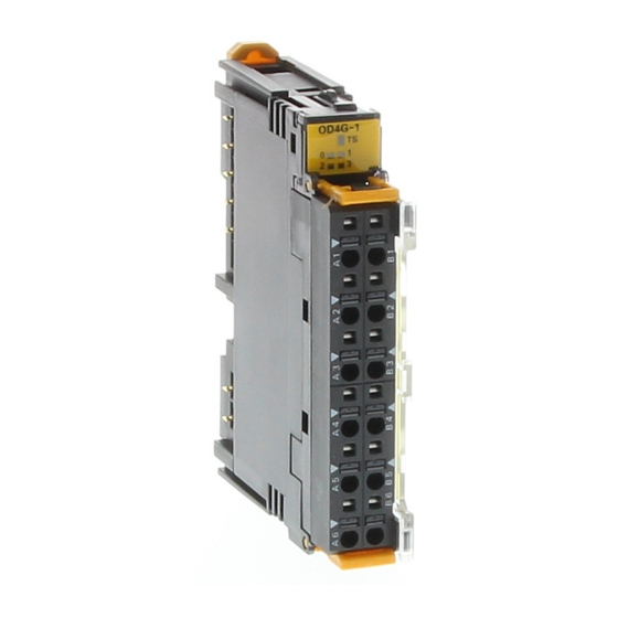
Page 87: Four-Point Transistor Output Units: Grt1-Od4 (Npn), Grt1-Od4-1 (Pnp), Grt1-Od4G-1 (Pnp), Grt1-Od4G-3 (Pnp)
Section 4-6 Digital I/O Units Dimensions (Same for GRT1-ID4 and GRT1-ID4-1) (88.5) 14.1 74.4 (74.4) OMRON 4-6-2 Four-point Transistor Output Units: GRT1-OD4 (NPN), GRT1-OD4-1 (PNP), GRT1-OD4G-1 (PNP), GRT1-OD4G-3 (PNP) Output Specifications Item Specification Model GRT1-OD4 GRT1-OD4-1 GRT1-OD4G-1 GRT1-OD4G-3 Internal I/O common NPN Number of I/O points 4 outputs Rated output current 0.5 A/point max. - Page 88 Section 4-6 Digital I/O Units Note With the GRT1-OD4G-1 or GRT1-OD4G-3, even if a short-circuit occurs on one output, the other three outputs will operate normally. Rated Output Current of the GRT1-OD4G-3 The total power that may be delivered by the outputs of the GRT1-OD4G-3 depends on the ambient temperature.
- Page 89 Section 4-6 Digital I/O Units Component Names and Functions (Same for GRT1-OD4, GRT1-OD4-1, GRT1-OD4G-1, GRT1-OD4G-3) LED indicators LED indicators OD4G-3 Indicate the Unit's status. Indicate the Unit's status. Test pin Test pin Release button Release button Terminal insertion hole Terminal insertion hole Terminal Block Terminal Block GRT1-OD4G-3...
- Page 90 Section 4-6 Digital I/O Units GRT1-OD4-1 (PNP) Main block Terminal block Base block I/O LED Internal circuits Voltage step-down Internal circuits GRT1-OD4G-1 (PNP) Main block Terminal block Base block Short- I/O LED circuit detection Internal circuits Voltage step-down Internal circuits...
- Page 91 Section 4-6 Digital I/O Units GRT1-OD4G-3 (PNP) Terminal Base block Main block block Short- I/O LED circuit detection Internal circuits Voltage step-down V (2) Internal circuits G (2) Wiring GRT1-OD4 (NPN) Solenoid, valve, etc. GRT1-OD4-1 (PNP) Solenoid, valve, etc.
- Page 92 Section 4-6 Digital I/O Units GRT1-OD4G-1 (PNP) Solenoid, valve, etc. 3-wire actuator GRT1-OD4G-3 (PNP) Solenoid, valve , etc. 24 VDC 3-wire actuator Dimensions (Same for GRT1-OD4, GRT1-OD4-1, GRT1-OD4G-1, and GRT1-OD4G-3) (88.5) 14.1 74.4 (74.4) OMRON...
-
Page 93: Eight-Point Dc Input Units: Grt1-Id8 (Npn) And Grt1-Id8-1 (Pnp)
Section 4-6 Digital I/O Units 4-6-3 Eight-point DC Input Units: GRT1-ID8 (NPN) and GRT1-ID8-1 (PNP) Input Specifications Item Specification Model GRT1-ID8 GRT1-ID8-1 Internal I/O common NPN Number of I/O points 8 inputs ON voltage 15 VDC min. (between each 15 VDC min. (between each input terminal and V) input terminal and G) OFF voltage... - Page 94 Section 4-6 Digital I/O Units Internal Circuits GRT1-ID8 (NPN) Terminal block Base block Main block I/O LED Internal circuits Internal circuits 4 × G GRT1-ID8-1 (PNP) Base block Terminal block Main block I/O LED Internal circuits 4 × V Internal circuits...
- Page 95 Section 4-6 Digital I/O Units Wiring GRT1-ID8 (NPN) GRT1-ID8 (NPN) When using 3-wire sensors, wire using the GRT1-PC8 I/O Power Connection Unit as shown in the following figure. 3-wire sensors GRT1-PC8 GRT1-ID8 3-wire sensors Black (white) Black (white) Brown (red) Brown (red) Blue (black) Blue (black)
- Page 96 Section 4-6 Digital I/O Units When connecting 2-wire sensors, wire using the GRT1-PC8-1 I/O Power Connection Unit as shown in the following figure. A single I/O Power Connec- tion Unit can be connected to up to two GRT1-ID8 Units. 2-wire sensors 2-wire sensors GRT1-ID8 GRT1-PC8-1...
- Page 97 Section 4-6 Digital I/O Units If the Unit connected on the left needs to be isolated, wire using the GRT1- PD8-1 I/O Power Feed Unit. When using the GRT1-PD8-1 I/O Power Feed Unit, however, a maximum of seven sensors can be connected, as shown in the following figure.
- Page 98 Section 4-6 Digital I/O Units Dimensions (Same for GRT1-ID8 and GRT1-ID8-1) (88.5) 14.1 74.4 (74.4) OMRON...
-
Page 99: Eight-Point Transistor Output Units: Grt1-Od8 (Npn), Grt1-Od8-1 (Pnp), And Grt1-Od8G-1 (Pnp)
Section 4-6 Digital I/O Units 4-6-4 Eight-point Transistor Output Units: GRT1-OD8 (NPN), GRT1- OD8-1 (PNP), and GRT1-OD8G-1 (PNP) Output Specifications Item Specification Model GRT1-OD8 GRT1-OD8-1 GRT1-OD8G-1 Internal I/O common Number of I/O points 8 outputs Rated output current 0.5 A/point max. Output overcurrent and Not supported. - Page 100 Section 4-6 Digital I/O Units Internal Circuits GRT1-OD8 (NPN) Main block Terminal block Base block I/O LED Internal circuits Voltage step-down 4 × V Internal circuits GRT1-OD8-1 (PNP) Main block Terminal block Base block I/O LED Internal circuits Voltage step-down Internal circuits 4 ×...
- Page 101 Section 4-6 Digital I/O Units Wiring GRT1-OD8 (NPN) When using a GRT1-PC8 I/O Power Connection Unit, wire according to the following figure. Up to two GRT1-0D8 Units can be wired with a single I/O Power Connection Unit. GRT1-OD8 GRT1-PC8 GRT1-OD8 Solenoids, valves, etc.
- Page 102 Section 4-6 Digital I/O Units GRT1-OD8-1 (PNP) When using a GRT1-PC8-1 I/O Power Connection Unit, wire according to the following figure. Up to two GRT1-0D8 Units can be wired with a single Power Connection Unit. GRT1-OD8-1 GRT1-PC8-1 GRT1-OD8-1 Solenoids, valves, etc. Solenoids, valves, etc.
- Page 103 Section 4-6 Digital I/O Units Dimensions (Same for GRT1-OD8, GRT1-OD8-1, and GRT1-OD8G-1) (88.5) 14.1 74.4 (74.4) OMRON...
-
Page 104: Two-Point Relay Output Unit: Grt1-Ros2
Section 4-6 Digital I/O Units 4-6-5 Two-point Relay Output Unit: GRT1-ROS2 Common Specifications Item Specifications Communications power 24 VDC (20.4 to 26.4 VDC) supply voltage I/O power supply voltage 24 VDC (20.4 to 26.4 VDC) Noise immunity Conforms to IEC61000-4-4, 2.0 kV (power supply line) Vibration resistance 10 to 60 Hz: 0.7 mm double amplitude 60 to 150 Hz: 50 m/s... - Page 105 Section 4-6 Digital I/O Units Note The figure above gives the life expectancy for individual relays. Always use the Relay Output Unit within its operating range. Using the Unit outside its operating range may result in failure of the Unit. Component Names and Functions LED indicators ROS2...
-
Page 106: Four-Point Ac Input Units: Grt1-Ia4-1 And Grt1-Ia4-2
(or DC power supply) Load AC power supply (or DC power supply) Load Dimensions (88.5) 14.1 74.4 (74.4) OMRON 4-6-6 Four-point AC Input Units: GRT1-IA4-1 and GRT1-IA4-2 Input Specifications Item Specification Model GRT1-IA4-1 GRT1-IA4-2 Number of I/O points 4 inputs I/O power supply Not used. - Page 107 Section 4-6 Digital I/O Units Item Specification OFF response time 55 ms max. 40 ms max. Number of circuits 4 (no common) It is necessary to share the same neutral AC signal or make sure that the voltage between two input circuits is 600 V max. (Refer to Wiring on page 87.) Insulation resistance 20 MΩ...
- Page 108 Section 4-6 Digital I/O Units Note: No common signal for inputs. Note: Common signal for four inputs. Dimensions (88.5) 14.1 74.4 (74.4) OMRON...
- Page 109 SECTION 5 Analog I/O Units This section provides the information required to operate Analog Input Units and Analog Output Units, including functions, status areas, windows, specifications, wiring, data allocation, and settings. Overview of Analog I/O Units ........5-1-1 Analog I/O Units.
-
Page 110: Overview Of Analog I/O Units
Section 5-1 Overview of Analog I/O Units Overview of Analog I/O Units This section provides an overview of Analog I/O Units, including details on functions and setting methods for each Unit. 5-1-1 Analog I/O Units In addition to the functions common to the GRT1 Series (backup, restore, online conversion, etc.), other functions specific to Analog I/O Units (scaling, peak/bottom hold, etc.) are available. - Page 111 Section 5-1 Overview of Analog I/O Units Unit GRT1 Series DRT2 Series Model GRT1-AD2 DRT2-AD04 Moving average Supported. (Set using Setting Tool.) Supported. (Set using DeviceNet Config- urator.) Off-wire detection Supported. Scaling, offset compensation, peak/ Supported. (Set using Setting Tool.) Supported.
-
Page 112: List Of Data Processing Functions
Section 5-1 Overview of Analog I/O Units 5-1-3 List of Data Processing Functions The following tables list the data processing functions that can be used with Analog I/O Units. Refer to 5-4-3 Functions and Settings for details on func- tions and setting methods. GRT1-AD2 Analog Input Units Function Details... -
Page 113: Data Processing Flowcharts (Analog Input Units)
Section 5-1 Overview of Analog I/O Units 5-1-4 Data Processing Flowcharts (Analog Input Units) Analog Input Value The following math operations can be performed on the external analog input value. The values obtained after processing (analog input values) can be allo- cated as I/O for the Master. -
Page 114: I/O Data
Section 5-1 Overview of Analog I/O Units Flow of Data in Analog Input Units Moving average, scal- Six types of data ing enabled/disabled Select one of the six types of data and allocate as analog data. Analog input value 1 Peak value 2 Bottom value 3 Analog Data... -
Page 115: Status Areas
Section 5-2 Status Areas Output Data I/O data Details Hold Flags (1 output byte) Used with each of the hold functions (peak, bottom, top, and valley) to control the execu- tion timing of hold functions from the Master. GRT1-DA2@ Analog Analog Output Units support one type output data. - Page 116 Section 5-2 Status Areas Contents Description Cumulative Counter Flag Turns ON when the cumulative value exceeds the monitoring set value. OFF: Within range (below monitoring set value) ON: Out of range (at or above monitoring set value) Reserved. Reserved. Reserved. Reserved.
-
Page 117: Maintenance Information Window
Section 5-3 Maintenance Information Window Contents Description Error Output Flag ON while error is being output. OFF: Normal; ON: Error being output Cumulative Counter Flag Turns ON when the cumulative value exceeds the monitoring set value. OFF: Within range (below monitoring set value) ON: Out of range (at or above monitoring set... -
Page 118: Checking Maintenance Information
Section 5-3 Maintenance Information Window 5-3-1 Checking Maintenance Information There are two ways to check maintenance information. One way is to right- click in the Main Window of the Setting Tool and select Maintenance Infor- mation. The other way is to double-click the Unit in the Maintenance Mode Window, click the I/O Module Tab, select the desired Unit, and click the View Button to display the Maintenance Information Window of the I/O Unit. -
Page 119: Analog Input Units
Section 5-4 Analog Input Units Display Area Item Description I/O Comment Displays up to 32 characters of text as a comment. A separate comment can be set for each input. Last Maintenance Displays the last maintenance date and time. (All models.) Date Present Value Displays the present analog value. - Page 120 Section 5-4 Analog Input Units Item Specifications Storage temperature –25 to 65°C (with no icing or condensation) Mounting 35-mm DIN Track mounting Performance Specifications Item Specifications Voltage input Current input Input points 2 points (inputs 0 to 1) Input signal range 0 to 5 V 0 to 20 mA 1 to 5 V...
- Page 121 Section 5-4 Analog Input Units Names and Functions of Parts LED Indicator Displays Unit status. Terminal Test Pins Block Release Buttons Terminal Insertion Holes DIP Switch Used to set input range. Setting the Input Range Setting with the DIP The input signal range can be set using the DIP switch or the Setting Tool. Switch Each pin is set according to the following table.
- Page 122 Section 5-4 Analog Input Units Input Range Settings ■ Inputs 0 and 1 (Shared Setting) Input range Pin 1 Pin 2 Pin 3 0 to 5 V 1 to 5 V 0 to 10 V –10 to 10 V 4 to 20 mA 0 to 20 mA Cannot set for other ranges.
- Page 123 Section 5-4 Analog Input Units Internal Circuits Terminal block Main block Base block RSV × 2 510 kΩ Photo- coupler 0− 510 kΩ SHT0A Internal 250 Ω circuits SHT0B Isolated power Internal supply circuits circuit 510 kΩ 1− 510 kΩ SHT1A 250 Ω...
- Page 124 Section 5-4 Analog Input Units ages are expressed as two’s complements (16 bits). When a disconnection occurs, the data equivalent to 0 V input will be used (0000 hex). Conversion data Hexadecimal (decimal) 189C (6300) 1770 (6000) 0000 (0) −0.25 V Voltage 5 V 5.25 V FED4 (−300)
- Page 125 Section 5-4 Analog Input Units ■ Input Range: 10 to 10 V – The voltage range 10 to 10 V corresponds to F448 to 0BB8 hex ( 3,000 to – – 3,000). The convertible data range is F31C to 0CE4 hex ( 3,300 to 3,300).
-
Page 126: I/O Data Allocation Methods
Cycle for details. Dimensions (88.5) 14.1 74.4 (74.4) OMRON 5-4-2 I/O Data Allocation Methods Selecting I/O Data to Use one of the following methods to select data for allocating in the Communi- be Allocated cations Unit and then perform remote I/O communications. - Page 127 Section 5-4 Analog Input Units ■ When the Default Settings Are Used When the Analog Input Unit’s default settings are used, only the analog input values are selected as I/O data and allocated in the two words (four bytes) of the Master’s Input Area, as shown in the following diagram.
- Page 128 Section 5-4 Analog Input Units 4. Click the General Tab and select the desired I/O data from the pull-down menu on the Default Connection Path (In) Field. In the following example Analog Data is selected. 5. Return to the General Tab Page, click the Download Button, and then click the Reset Button to reset the Unit.
- Page 129 Section 5-4 Analog Input Units 3. Open the tab page for the input for which analog data is to be selected, and select from the pull-down list the type of data to be allocated to Analog Da- 4. Return to the General Tab Page, click the Download Button and then click the Reset Button to reset the Unit.
- Page 130 Section 5-4 Analog Input Units The details of each byte are shown in the following table. Byte Abbreviation Name Details V_STx Valley Detection Tim- Turns ON when a valley is ing Flag detected by the valley hold function and then turns OFF after the one-shot time has elapsed.
-
Page 131: Functions And Settings
Section 5-4 Analog Input Units Abbrevi- Name Details ation V_STx Top/val- Valley Detec- Used with the valley hold func- ley detec- tion Timing Flag tion. tion Turns ON when a valley is timing detected, and turns OFF after the one-shot time has lapsed. T_STx Top Detection Used with the top hold function. - Page 132 Section 5-4 Analog Input Units conversion cycle speed is increased. For details on conversion cycle time, refer to 5-4-4 Calculating the Conversion Cycle. Conversion points Details 2 points (default) Converting Inputs 0 to 1. GRT1-AD2 All used. 1 point Converting Input 0. GRT1-AD2 Input 0 only used.
- Page 133 Section 5-4 Analog Input Units 2. Click the I/O Module Tab. 3. Click the Edit Button on the I/O Module Tab Page. The Edit Unit Parame- ters Window will be displayed. 4. Click the General Tab and select the number of conversion points from the pull-down menu in the Available Channel Field.
- Page 134 Section 5-4 Analog Input Units Moving Average This function calculates the average value (moving average) of the previous Processing eight inputs, and uses the resulting value as conversion data. When the input value fluctuates frequently, averaging can be used to produce a stable input value, as shown in the following diagram.
- Page 135 Section 5-4 Analog Input Units for ladder programming in the Master to perform math operations. The follow- ing two methods of input scaling can be used. Default Scaling Analog input values (count values) are converted to the original voltage and μ...
- Page 136 Section 5-4 Analog Input Units Upper limit 7FFE 100% scaling value Scaled line 0% scaling Offset value (–28,000 to 28,000) Input signal range 100% Setting Procedure (Example: DeviceNet Configurator) 1. In the Network Configuration Window for the Slice I/O Terminal, double- 1,2,3...
- Page 137 Section 5-4 Analog Input Units 5. Click the Scaling Tab, and select either Default Scaling or User Scaling. The following example shows when Default Scaling is selected. 6. For user scaling, set the 0% value in the Scaling point 1 Field, and set the 100% value in the Scaling point 2 Field.
- Page 138 Section 5-4 Analog Input Units 7. For offset compensation, set the offset value in the Scaling Offset Field. Also select either Default Scaling or User Scaling in the Scaling Type Field. 8. Return to the General Tab Page, click the Download Button, and then click the Reset Button to reset the Unit.
- Page 139 Section 5-4 Analog Input Units turned ON may be the data from when the Hold Flag was OFF. To collect peak/bottom hold data using the Hold Flag at the Master, configure a ladder program that considers the transmission delay when the Hold Flag is turned ON, then enables the peak/bottom hold values after a fixed time interval.
- Page 140 Section 5-4 Analog Input Units 5. To allocate the Hold Flags (output) in the default connection path, click the General Tab and select Holding Value from the pull-down menu in the Default Connection Path (Out) Field. 6. Click the Download Button and then click the Reset Button to reset the Unit.
- Page 141 Section 5-4 Analog Input Units ■ Example of Valley Hold Valley hold value Analog input value Last value is held. Hold value Hold Flag Hold function starts Hold function stops Top/Valley Detection Timing Flag One-shot time Note 1. A delay in network transmission time will occur from the time the Hold Flag turns ON (or OFF) in the Master’s ladder program until notification of the flag’s status is actually sent to the Unit.
- Page 142 Section 5-4 Analog Input Units 4. Select the tab page for the input where top/valley hold is to be set, and se- lect the Top/Valley Hold Check Box in the Function Choice Area. 5. To allocate the Hold Flag (output) in the default connection path, click the General Tab, and select Holding Value from the pull-down menu in the Default Connection Path (Out) Field.
- Page 143 Section 5-4 Analog Input Units value. This will cause the start of data holding to be delayed after the actual top or valley value occurs, as shown in the following diagram. ■ Timing for Setting Data Analog input value Set hysteresis value × 2 Valley hold value Top/Valley Detection Timing Flag...
- Page 144 Section 5-4 Analog Input Units One-shot Time Setting 1. Input the desired value in the SHOT Off Delay Field on the Top/Valley Tab 1,2,3... Page in the Function Choice Area. 2. Return to the General Tab Page, click the Download Button, and then click the Reset Button to reset the Unit.
- Page 145 Section 5-4 Analog Input Units be regarded as the rate of change. To prevent this occurring, use moving average processing, which will set a longer sampling cycle. Desired gradient Fluctuation in analog value Short sampling cycle Long sampling cycle Setting Procedure (Example: DeviceNet Configurator) 1.
- Page 146 Section 5-4 Analog Input Units 5. To set the sampling cycle, click the Rate of Change Tab and input the de- sired value for the sampling cycle in the Sampling Rate Field. 6. Return to the General Tab Page, click the Download Button, and then click the Reset Button to reset the Unit.
- Page 147 Section 5-4 Analog Input Units Setting Hysteresis The Comparator Result Flag turns OFF when the value is lower than the hys- teresis width (H or HH alarm occurs) or exceeds it (L or LL alarm occurs), as shown in the following diagram. If the analog value fluctuates around the threshold, and the flag repeatedly turns ON or OFF, setting hysteresis will sta- bilize the flag operation.
- Page 148 Section 5-4 Analog Input Units 4. Select the tab page for the input where the comparator function is to be set, and select the Comparator Check Box in the Function Choice Area. 5. Click the Comparator Tab and set each of the alarm values. The example here shows the setting for Alarm Trip Point High (HH).
- Page 149 Section 5-4 Analog Input Units 6. To set the hysteresis value, input the desired value in the Hysteresis Field. Note The hysteresis value set for the comparator function is also used by the top/ valley hold function. 7. To set the OFF delay function, input the desired value in the Comparator Off Delay Field.
- Page 150 Section 5-4 Analog Input Units Off-wire Detection When a disconnection occurs in an analog input line (voltage input or current input), the Off-wire Detection Flag turns ON for each input that is enabled in the number of AD conversion points. The Off-wire Detection Flags are included in the Analog Status Flags.
- Page 151 Section 5-4 Analog Input Units 4. Select the tab page for the input to be adjusted, and click the Adjustment Button. (At the same time set the input range again.) 5. Input the voltage (or current) transmitted from the connected device to the Unit’s input terminal that is equivalent to the 100% value.
- Page 152 Section 5-4 Analog Input Units 8. Click the Fix lower adjusting Value Button, and input the adjusted value. 9. To return an adjusted value to the default setting, click the Default Setting Button. 10. Close the Adjustment Window, return to the General Tab Page, click the Download Button, and then click the Reset Button to reset the Unit.
- Page 153 Section 5-4 Analog Input Units DRT2-AD2 Unit Divisions Hour 3.6 s (1/1,000 hour) Minute 60 ms (1/1,000 minute) Setting Procedure (Example: DeviceNet Configurator) 1. In the Network Configuration Window for the Slice I/O Terminal, double- 1,2,3... click the icon of the Slice I/O Terminal that is to be set. Alternatively, right- click the icon and select Parameters - Edit.
- Page 154 Section 5-4 Analog Input Units 5. To set the counter unit, click the Cumulated Count Tab and select Hour or Minute from the pull-down menu in the Cumulated Timer Field. 6. To set the monitor value, click the Cumulated Count Tab, and input the desired value in the Threshold Cumulated Counter Field.
- Page 155 Section 5-4 Analog Input Units Last Maintenance The last maintenance date can be set in the Unit separately for the Unit and Date the connected devices. It enables the user to easily determine the next main- tenance date. The date can be set using the Setting Tool. Setting Procedure (Example: DeviceNet Configurator) ■...
-
Page 156: Calculating The Conversion Cycle
Section 5-4 Analog Input Units 2. Click the tab page for the input that is connected to a connecting device requiring the last maintenance date to be set. Select the applicable date from the pull-down menu in the Last Maintenance Date Field. (To enter the current date, select Today, which is at the bottom of the pull-down menu.) 3. -
Page 157: Analog Output Units
Section 5-5 Analog Output Units The following table shows the additional time required for each function (unit: ms). Math operation Additional time for each point Moving average 0.045 Scaling 0.055 Peak/bottom hold 0.025 Top/valley hold 0.070 Comparator 0.065 Rate of change 0.030 Cumulative counter 0.035... - Page 158 Section 5-5 Analog Output Units Item Specifications GRT1-DA2V Voltage output GRT1-DA2C Current output DA conversion data –10 to 10 V range: F448 to 0BB8 hex full scale (–3,000 to 3,000) Other ranges: 0000 to 1770 hex full scale (0 to 6,000) DA conversion range: ±5% FS of the above data ranges.
- Page 159 Section 5-5 Analog Output Units Pin No. Setting Specifications Reserved Fixed at OFF. Set the range setting method. OFF: Set using Setting Tool. ON: Set using DIP switch. Default setting: OFF Output range Pin 1 Pin 2 Pin 3 0 to 5 V (Factory set- Fixed at OFF.
- Page 160 Section 5-5 Analog Output Units 5. Click the Output Range Field, and select the desired range. 6. Return to the General Tab Page, click the Download Button, and then click the Reset Button to reset the Unit. 7. Click the OK Button to exit. Internal Circuits GRT1-DA2V Main block...
- Page 161 Section 5-5 Analog Output Units GRT1-DA2C Terminal block Main block Base block RSV × 6 Photo- coupler Internal I0− circuits Internal Isolated circuits power supply circuit I1− RSV × 2 Wiring The terminal wiring varies according to whether voltage or current output is used.
- Page 162 Section 5-5 Analog Output Units Output Range: 1 to 5 V The values 0000 to 1770 hex (0 to 6,000) correspond to the voltage range 1 to 5 V. The output range is 0.8 to 5.2 V. Voltage 5.2 V 0.8 V Conversion data Hexadecimal (decimal)
- Page 163 The NEG instruction can be used to obtain two’s complements from absolute values. Note Although the number of DA conversion points is set from the Setting Tool, the allocated data does not change (i.e., two words are used). Dimensions (88.5) 14.1 74.4 (74.4) OMRON...
-
Page 164: I/O Data And Allocation Methods
Section 5-5 Analog Output Units 5-5-2 I/O Data and Allocation Methods When the Analog Output Unit’s default settings are used, output data is allo- cated. No special settings are required. Two words (four bytes) of output data are allocated as two’s complement. Analog output value for Output 0 Analog output value for Output 1 5-5-3... - Page 165 Section 5-5 Analog Output Units Note Reverse scaling, where the 0% scaling value is higher than the 100% scaling value, is also supported. Offset Compensation Offset compensation is used to compensate for error that occurs during scal- ing. The offset amount is added to the scaled line before processing, as shown in the following diagram.
- Page 166 Section 5-5 Analog Output Units 4. Select the tab page for the output where scaling is to be performed, and select the Scaling Check Box in the Function Choice Area. 5. To select the scaling type, click the Scaling Tab, and select either Default Scaling or User Scaling.
- Page 167 Section 5-5 Analog Output Units 6. For user scaling, set the 0% value in the Scaling point 1 Field, and set the 100% value in the Scaling point 2 Field. 7. For offset compensation, set the offset value in the Scaling Offset Field. Also select either Default Scaling or User Scaling in the Scaling Type Field.
- Page 168 Section 5-5 Analog Output Units User Adjustment Depending on factors such as the characteristics and connection methods of the output device, the output can be adjusted to compensate for error in the final output. The following diagram shows when compensation is applied to the conversion line at the two points for 0% and 100%.
- Page 169 Section 5-5 Analog Output Units 4. Select the tab page for the output to be adjusted, and click the Adjustment Button. (At the same time, set the output range again.) Adjusting the Low Limit 5. Output the value that is equivalent to 0% from the Master Unit. Always per- form adjustment with the 0% value.
- Page 170 Section 5-5 Analog Output Units Adjusting the High Limit 10. Output the value from the Master Unit that is equivalent to the Output Unit’s maximum (100%) value. Adjustment is best performed using the 100% value, but can be performed using a lower value. 11.
- Page 171 Section 5-5 Analog Output Units Monitor values can also be set in the Unit. When the cumulated count value exceeds the set monitor value, the Cumulative Counter Flag in the area for Generic Status Flags turns ON. Analog output value Cumulated value (count ×...
- Page 172 Section 5-5 Analog Output Units 4. Select the tab page for the output where the cumulated counter is to be set, and select the Cumulated Count Check Box in the Function Choice Area. 5. To set the counter unit, click the Cumulated Count Tab and select Hour or Minute from the pull-down menu in the Cumulated Timer Field.
- Page 173 Section 5-5 Analog Output Units 6. To set the monitor value, click the Cumulated Count Tab, and input the desired value in the Threshold Cumulated Counter Field. 7. Return to the General Tab Page, click the Download Button, and then click the Reset Button to reset the Unit.
- Page 174 Section 5-5 Analog Output Units Setting Procedure (Example: DeviceNet Configurator) 1. In the Network Configuration Window for the Slice I/O Terminal, double- 1,2,3... click the icon of the Slice I/O Terminal that is to be set. Alternatively, right- click the icon and select Parameters - Edit. The Edit Device Parameters Window will be displayed.
- Page 175 SECTION 6 Temperature Input Units This section provides the information required to operate the Temperature Input Units, including functions, status areas, windows, specifications, wiring, data allocation, and settings. Overview of the Temperature Input Units......6-1-1 Temperature Input Units .
-
Page 176: Overview Of The Temperature Input Units
Section 6-1 Overview of the Temperature Input Units Overview of the Temperature Input Units This section provides an overview of the Temperature Input Units, including details on functions and setting methods. 6-1-1 Temperature Input Units In addition to the functions common to the GRT1 Series (backup, restore, online conversion, etc.), other functions specific to the Temperature Input Units (scaling, peak/bottom hold, etc.) are available. - Page 177 Section 6-1 Overview of the Temperature Input Units Series GRT1 Series DRT2 Series Model GRT1-TS2P GRT1-TS2PK DRT2-TS04P Moving average Supported. (Set using Setting Tool.) Supported. (Set using DeviceNet Configurator.) Off-wire detection Supported. Input error detection disable setting Supported. Not supported. Scaling, offset compensation, peak/bot- Supported.
-
Page 178: Comparison With Previous Models With Thermocouple Inputs
Section 6-1 Overview of the Temperature Input Units 6-1-3 Comparison with Previous Models with Thermocouple Inputs Series GRT1 Series DRT2 Series Model GRT1-TS2T DRT2-TS04T Input type Thermocouple input Maintenance method Terminal block and main block can be Removable terminal block separated. -
Page 179: List Of Data Processing Functions
Section 6-1 Overview of the Temperature Input Units 6-1-4 List of Data Processing Functions GRT1-TS2@ Temperature Input Units Function Details Default Moving average Calculates the average of the past eight temperature input Moving average disabled. values, and produces a stable input value even when the input value is unsteady. -
Page 180: Selecting Data
Section 6-1 Overview of the Temperature Input Units Analog processing is performed according to the following flowchart. Input Moving Scaling average Temperature input value 1 Cumulated Top/Valley Peak/Bottom Rate of change value Peak Cumulated Rate of change value 2 value 4 value value 6 Bottom... -
Page 181: I/O Data
Section 6-1 Overview of the Temperature Input Units Flow of Data in Temperature Input Units Moving average, scal- ing enabled/disabled Six types of data Temperature input value 1 1/100 Display (2 words/input) Peak value 2 Temperature data (allocated I/O data) Bottom value 3 Either can be allocated for the Master as... -
Page 182: Status Areas
Section 6-2 Status Areas Input data Details Temperature Status Flags Used to allocate the bits for the Comparator Result Flags, Top/Valley Detection Timing (2 input bytes) Flags, and Off-wire Detection Flags. The function of each bit is as follows: • Comparator Result Flags Allow control of the judgement results only, without allocating temperature values •... - Page 183 Section 6-2 Status Areas Contents Description Reserved. Reserved. Reserved. Reserved. Temperature Input Warning Turns ON when the temperature data Flag exceeds the range that can be dis- played or the monitoring value set for OFF: Within range (below the comparator function. monitoring set value) ON: Out of range (at or above monitoring set value)
-
Page 184: Maintenance Information Window
Section 6-3 Maintenance Information Window Contents Description Off-wire Detection Flag Turns ON when a sensor is discon- nected or a cold junction compensator error occurs. OFF: Normal or the input error detec- tion disabled setting is set to disable detecting input errors. ON: Disconnection or cold junction compensator error Cold junction compensator... - Page 185 Section 6-3 Maintenance Information Window General Tab Page Status check boxes Display Area Item Description Comment Displays up to 32 characters of text set as the Unit comment. Last Maintenance Displays the last maintenance date that was set. Date Unit Conduction Displays the total time that the Unit has been ON (cumulated Time power ON time).
- Page 186 Section 6-3 Maintenance Information Window Display Area Item Description Input Type Shows the present input type. Display Mode Indicates the number of digits displayed. 0000: No decimal point. (GRT1-TS2T only) 0000.0: Displays to the 10ths place (0.1). 0000.00: Displays to the 100ths place (0.01). I/O Comment Displays up to 32 characters of text as a comment.
-
Page 187: Temperature Input Units
Section 6-4 Temperature Input Units Item Description Comparison Displays the inputs used in the error calculation. Description Result Value Displays the calculation results. Note (1) When a result value exceeds the monitoring set value, a red alarm icon will be displayed to the left of the comparison number. (2) When either of the comparison inputs is disconnected (off-wire detected), the result value will be set to 0.00 and a yellow alarm icon will be dis- played to the left of the comparison number. - Page 188 Section 6-4 Temperature Input Units Performance Specifications GRT1-TS2P/TS2PK Item Specifications Model GRT1-TS2P GRT1-TS2PK Input Platinum resistance thermometer Number of I/O points 2 inputs (Two input words are allocated in the Master when normal display mode is selected or 4 input words are allocated when 1/100 display mode is selected.) −...
- Page 189 Section 6-4 Temperature Input Units GRT1-TS2T Items Specifications Model GRT1-TS2T Input type Thermocouple Number of 2 inputs (Two input words are allocated in the Master when normal inputs display mode is selected or 4 words are allocated when 1/100 dis- play mode is selected.) Input type R, S, K, J, T, E, B, N, L, U, W, or PL2...
- Page 190 Section 6-4 Temperature Input Units The following are exceptions. Input type Input accuracy K, T, or N below −100°C ± ° ± 1 digit max. ± ° ± U, L, or PL2 1 digit max. ± ° ± R or S below 200°C 1 digit max.
- Page 191 Section 6-4 Temperature Input Units Terminal Block Main Block The serial number is on the label The serial number is printed on attached to the terminal block as the main bock as shown in the shown in the following figure. following figure.
- Page 192 Section 6-4 Temperature Input Units Name Color Status Meaning ERR1 Error An input error has occurred in input 1. An error has occurred in the cold junction compensator (GRT1-TS2T only). Not lit Normal status There is no input error for input 1. Note The ERR indicator will not light or flash if input error detection has been disabled (i.e., if the input error detection disable setting has been set to disable detection).
- Page 193 Section 6-4 Temperature Input Units GRT1-TS2P ■ Input type PT100 (−200 to 850°C) PT100 (−200 to 200°C) GRT1-TS2PK ■ Input type PT1000 (−200 to 850°C) PT1000 (−200 to 200°C) GRT1-TS2T ■ Input type K (−200 to 1,300°C) J (−100 to 850°C) Note 1.
- Page 194 Section 6-4 Temperature Input Units 5. Double-click the Value Setting for the Input Type on the Range/Data Allo- cation Tab Page and select the desired input type from the pull-down menu. 6. Return to the General Tab Page, click the Download Button, and then click the Reset Button to reset the Unit.
- Page 195 Section 6-4 Temperature Input Units Input type ° ° Range in Range in − − L (−100 to 850°C) 100 to 850 100 to 1,500 L (0.0 to 400.0°C) 0.0 to 400.0 0.0 to 750.0 − − 200.0 to 400.0 300.0 to 700.0 −...
- Page 196 Section 6-4 Temperature Input Units GRT1-TS2PK Normal Display Mode ■ Type °C Display °F Display PT1000 − 220.0 to 870.00 F768 to − 320.0 to 1520.0 F380 to 3B60 (− ° 21FC 200 to 850 − − PT1000 220.0 to 220.00 F768 to F380 to 0FA0 320.0 to 400.0 (−...
- Page 197 Section 6-4 Temperature Input Units °C °F Type Display Display −20 to 2,320 FFEC to 0910 −20 to 4,120 FFEC to 1018 80 to 1,820 0050 to 071C 280 to 3,220 0118 to 0C94 −20 to 1,320 FFEC to 0528 −20 to 2,320 FFEC to 0910 1/100 Display Mode ■...
- Page 198 Section 6-4 Temperature Input Units and the temperature data will be set to 7FFF. If the input temperature re- turns to the convertible range, the off-wire detection function will be reset automatically, the corresponding ERR indicator will go out, and normal conversion data will be stored.
- Page 199 Section 6-4 Temperature Input Units Terminal Arrangement and Wiring GRT1-TS2P/TS2PK When using a 2-wire sensor, short-circuit the SHT terminals for that input. 2-wire sensor 3-wire sensor Note If a 2-wire sensor is wired as shown below, the error in the accuracy will be much greater when compared to the wiring method in the above figure.
-
Page 200: Temperature Input Unit Display Modes
Section 6-4 Temperature Input Units If unused inputs are left disconnected, the Temperature Input Warning Flag in the Warning Status Area and the Off-wire Detection Flag in the Alarm Status will turn ON. If the Temperature Status Flag is used, the Off-wire Detection Flag will turn ON. - Page 201 Section 6-4 Temperature Input Units 1/100 Display Mode The input temperature data for all input types is transmitted to the Master as data with precision to the 100ths (0.01) digits. The temperature data is multi- plied by 100 and converted to 8-digit hexadecimal digital data (long binary val- ues).
-
Page 202: I/O Data Allocation Methods
Dimensions (88.5) 14.1 74.4 (74.4) OMRON 6-4-3 I/O Data Allocation Methods Either the default settings (i.e., the temperature input values) can be used, or the Setting Tool can be used to allocate Status Flags or other settings other than the temperature input value. - Page 203 Section 6-4 Temperature Input Units Using the Default When the Temperature Input Unit’s default settings are used, only the temper- Settings ature input values are selected as I/O data. Two words (four bytes) are allo- cated in the Master’s Input Area, as shown in the following diagram. Temperature Input Value for Input 0 Temperature Input Value for Input 1 Setting Data Using a Setting Tool...
- Page 204 Section 6-4 Temperature Input Units 4. Click the General Tab and select the desired I/O data from the pull-down menu on the Default Connection Path (In) Field. In the following example Temperature Data is selected. 5. Click the Download Button to download the setting, and then click the OK Button to return to the Edit Device Parameters Window.
- Page 205 Section 6-4 Temperature Input Units The data format used for allocating data in the Master is shown below. Data is allocated as two’s complements (4 bytes = 2 words). Temperature Data for Input 0 Temperature Data for Input 1 Temperature Data 1/100 This format is used to allocate temperature data in 1/100 Display Mode.
- Page 206 Section 6-4 Temperature Input Units The details for each bit are shown in the following table. Abbrevi- Name Details ation Compara- Low Low Limit Turns ON when the value of tor result Alarm Flag data allocated in Temperature Data drops below the Low Low Limit alarm setting.
- Page 207 Section 6-4 Temperature Input Units Temperature Data 1/100 Mode + Top/Valley Detection Timing Flags (Temperature Data (1/100) + Shot Status) This data pattern consists of the Temperature Data 1/100 Display Mode fol- lowed by the Top/Valley Detection Timing Flags and is allocated in the Master using the following data format (10 bytes = 5 words).
-
Page 208: Functions And Settings
Section 6-4 Temperature Input Units 3. Open the tab page for the input for which temperature data is to be select- ed, and select from the pull-down list the type of data to be allocated as the Temperature Data. 4. Return to the General Tab Page, click the Download Button, and then click the Reset Button to reset the Unit. - Page 209 Section 6-4 Temperature Input Units 4. Select the tab page for the input where moving average processing is to be performed, and select the Moving Average Check Box in the Function Choice Area. 5. Return to the General Tab Page, click the Download Button, and then click the Reset Button to reset the Unit.
- Page 210 Section 6-4 Temperature Input Units upper limit is 7FFE hex and the lower limit is 8000 hex. (In 1/100 Display Mode the upper limit is 7FFFFFFE hex and the lower limit is 80000000 hex.) Upper limit 7FFE 100% scaling value Scaled line 0% scaling Offset value...
- Page 211 Section 6-4 Temperature Input Units 5. Set the scaling point 0% value and scaling point 100% value. 6. When using an offset compensation, enter the offset value into the Scaling Offset Field. 7. Return to the General Tab Page, click the Download Button, and then click the Reset Button to reset the Unit.
- Page 212 Section 6-4 Temperature Input Units ■ Example of Bottom Hold Temperature input value The bottom value will be updated. Hold value Previous value Hold Flag Bottom hold value Hold function starts Hold function stops Note A delay in network transmission time will occur from the time the Hold Flag turns ON (or OFF) in the Master’s ladder program until notification of the flag’s status is actually sent to the Slave.
- Page 213 Section 6-4 Temperature Input Units 5. To allocate the Hold Flags (output) in the default connection path, click the General Tab and select Holding Value from the pull-down menu in the Default Connection Path (Out) Field. 6. Click the Download Button to execute the download procedure, and then click the OK Button to return to the Edit Device Parameters Edit Device Pa- rameters.
- Page 214 Section 6-4 Temperature Input Units occurs.) The comparator can be used to compare the top or valley value allo- cated as temperature data. (Refer to details on the comparator function.) ■ Example of Valley Hold Valley hold value Analog input value Last value is held.
- Page 215 Section 6-4 Temperature Input Units 4. Select the tab page for the input where top/valley hold is to be set, and se- lect the Top/Valley Hold Check Box in the Function Choice Area. 5. To allocate the Hold Flag (output) in the default connection path, click the General Tab, and select Holding Value from the pull-down menu in the Default Connection Path (Out) Field.
- Page 216 Section 6-4 Temperature Input Units ■ Timing for Setting Data Temperature input value Set hysteresis value × 2 Valley hold value Top/Valley Detection Timing Flag Delay ■ Setting Hysteresis (Example: DeviceNet Configurator) 1. Input the value for hysteresis in the Hysteresis Field in the Top/Valley Tab 1,2,3...
- Page 217 Section 6-4 Temperature Input Units One-shot Time Setting 1. Input the desired value in the SHOT Off Delay Field of the Top/Valley Tab 1,2,3... Page in the Function Choice Area. 2. Return to the General Tab Page, click the Download Button, and then click the Reset Button to reset the Unit.
- Page 218 Section 6-4 Temperature Input Units 3. Click the Edit Button on the I/O Module Tab Page. The Edit Unit Parame- ters Window will be displayed. 4. Select the tab page for the input where top/valley counter is to be set, and select the Top/Valley Option in the Function Choice Area.
- Page 219 Section 6-4 Temperature Input Units Temperature input value Temperature data Time Rate of change Derivative data Note If the sampling cycle is set to a small value, the rate of change will be sensi- tive to small changes. If the temperature data is subject to minute fluctuations, and the sampling cycle is shorter than the cycle of fluctuation, the fluctuation will be regarded as the rate of change.
- Page 220 Section 6-4 Temperature Input Units 4. Select the Tab Page for the input where rate of change is to be set, and select the Rate of Change Option in the Function Choice Area. 5. To set the sampling cycle, click the Rate of Change Tab and input the de- sired value for the sampling cycle in the Sampling Rate Field.
- Page 221 Section 6-4 Temperature Input Units When any of these values is exceeded, the Comparator Result Flag in the area for Temperature Status Flags turns ON. If an alarm does not occur, the Normal Flag (pass signal) turns ON. Set values HH alarm H alarm Normal Flag...
- Page 222 Section 6-4 Temperature Input Units Setting Procedure (Example: DeviceNet Configurator) 1. In the Network Configuration Window, double-click the icon of the Slice I/O 1,2,3... Terminal that is to be set. Alternatively, right-click the icon and select Pa- rameters - Edit. The Edit Device Parameters Window will be displayed. 2.
- Page 223 Section 6-4 Temperature Input Units 6. To set the hysteresis value, input the desired value in the Hysteresis Field. Note The hysteresis value set for the comparator function is also used by the top/valley hold function. 7. To set the OFF delay function, input the desired value in the Comparator Off Delay Field.
- Page 224 Section 6-4 Temperature Input Units Temperature 10°C Counting starts when this 85°C temperature is exceeded. When the temperature zone is set to 10°C above the set temperature (up to 95°C), the function counts how long the temperature is within Time that 10°C zone.
- Page 225 Section 6-4 Temperature Input Units 5. Click the Comparator Tab and select the desired type of zone from the pull-down menu on the Zone Type Field. 6. A threshold count value (time in seconds) can be set in the Threshold Zone Counter Field to indicate when the temperature has been in the tempera- ture zone longer than the threshold setting.
- Page 226 Section 6-4 Temperature Input Units 3. The comparison result will be read to a precision of 0.01, regardless of the setting. Temperature difference with device A is large. Is there an error? Device A Device B 580°C? 540°C Compare Detect temperature differences between inputs.
- Page 227 Section 6-4 Temperature Input Units 7. Return to the General Tab, click the Download Button, and then click the Reset Button to reset the Unit. 8. Click the OK Button and exit the window. 9. The comparison results can be checked in the Maintenance Information Window or Data comparison between channels Tab.
- Page 228 Section 6-4 Temperature Input Units Note (1) If an input is not being used, an input error will occur and an over range error and off-wire condition will be detected. This will cause the Temper- ature Input Warning Flag in the Warning Status Area and the Off-wire De- tection Flag in the Alarm Status to turn ON.
- Page 229 Section 6-4 Temperature Input Units 5. Click the Download Button, and then click the Reset Button to reset the Unit. 6. Click the OK Button to exit. ■ Setting the Last Maintenance Date of the Connected Device 1. In the Network Configuration Window, double-click the icon of the Slice I/O 1,2,3...
- Page 230 Section 6-4 Temperature Input Units (3) The meaning of the cumulated count depends on the decimal point posi- tion of the temperature value. Cumulated value Temperature input value (°C × hours or °C × minutes) Time Division width (See note.) Note The following table shows the divisions for the cumulative counter.
- Page 231 Section 6-4 Temperature Input Units 5. To set the counter unit, click the Cumulated Count Tab and select Hour or Minute from the pull-down menu in the Cumulated Timer Field. 6. To set the monitor value, click the Cumulated Count Tab, and input the desired value in the Threshold Cumulated Counter Field.
- Page 232 (1) Temperature Input Units are properly adjusted at the factory before ship- ment, so it is normally unnecessary to make adjustments. Use the user adjustment only when absolutely necessary. OMRON is not responsible for the results of user adjustment. If a mistake is made in the adjustment, the adjustment data can be cleared to return to the factory default set- tings.
- Page 233 Section 6-4 Temperature Input Units Adjustment Procedure for Use the following procedure to adjust the Temperature Input Terminal. Follow the GRT1-TS2T the flowchart closely for proper adjustment. Prepare the devices required for adjustment. Connect the devices required for adjustment (i.e., upper/lower limit adjustment).
- Page 234 Section 6-4 Temperature Input Units Connecting the Devices The following paragraphs explain how to connect the devices that must be required for GRT1-TS2T connected to the GRT1-TS2T for user adjustment. Wire the following devices Adjustment properly when adjusting the GRT1-TS2T. ■...
- Page 235 Section 6-4 Temperature Input Units Input Terminal Connections ■ Upper/Lower Limit Compensation Wiring Bias Compensation Wiring Compensating conductors ZERO-CON 0− 1− 0− 1− Short 0˚C/32˚F 0˚C/32˚F Output Input Two-wire ferrules Checking the Wiring and Making Adjustments Adjusting the GRT1-TS2T’s Upper and Lower Limit Values ■...
- Page 236 Section 6-4 Temperature Input Units 7. Select the Tab Page for the input that will be adjusted and click the Adjust- ment Button to open the Adjustment Window. 8. Adjust the lower limit value (lower adjusting value). Input 0 mV from the ref- erence voltage/current generator (STV) to the Temperature Input Termi- nal’s input terminals.
- Page 237 Section 6-4 Temperature Input Units Input type Input voltage 50 mV 50 mV 11. Click the Fix upper adjusting Value Button. The upper limit adjustment value will be stored in the Unit. 12. To check whether the user adjustment values have been accepted and the Unit is operating with adjustment values different from the factory defaults, click the right mouse button over the Slave icon and select Maintenance Information to open the Maintenance Information Window.
- Page 238 Section 6-4 Temperature Input Units Resetting User Adjustments ■ If it is necessary to reset the upper limit adjustment value, lower limit adjust- ment value, and bias compensation value to the factory defaults, click the Default Setting Button. The settings will be returned to the factory settings. The upper/lower limit adjustment values and bias compensation value are all initialized at the same time.
- Page 239 Section 6-4 Temperature Input Units Step Timing chart Stabilization time Input Unit’s power supply ON Wait at least 30 minutes. Wiring for input 1 upper/lower limit Temperature adjustment (Check whether additional Input Terminal’s time is required for devices stabilization time such as the STV, DMM, and ZERO-CON.) Input 1 upper/lower limit adjustment...
- Page 240 Section 6-4 Temperature Input Units GRT1-TS2P/TS2PK Adjustment Procedure Flow Prepare the devices required for adjustment. Connect the device for adjustment. To make the upper/lower limit adjustment, connect a six-dial resistance box to the Temperature Input Unit that is being adjusted. Turn ON the power to the associated system devices.
- Page 241 Section 6-4 Temperature Input Units Adjustment Device Connection Diagram Connect the six-dial resistance box to the input terminals. In the following example, the device is connected to input 0, but connect to the input 1 termi- nals when adjusting input 1. DeviceNet GRT1-TS2P or Setting Tool...
- Page 242 Section 6-4 Temperature Input Units Checking the Wiring and Making Adjustments Adjusting the Upper and Lower Limit Values ■ 1. Set the resistance value on the six-dial resistance box equivalent to the 1,2,3... test value and properly wire the box to the input of the Temperature Input Unit that is being adjusted.
- Page 243 Section 6-4 Temperature Input Units 9. Click the Fix Lower Adjusting Value Button. The lower limit adjustment value will be stored in the Unit. 10. Adjust the upper limit value (upper adjusting value). Refer to the following table for the appropriate resistance to input from the six-dial resistance box to the Temperature Input Unit’s input terminals.
- Page 244 Section 6-4 Temperature Input Units 13. To check whether the user adjustment values have been accepted and the Unit is operating with adjustment values instead of the default values, right-click device icon and select Maintenance Information to open the Maintenance Information Window. Select the tab page for the input that was adjusted.
- Page 245 SECTION 7 Counter Units and Positioning Unit This section provides information required to operate Counter Units and Positioning Units, including functions, status areas, windows, specifications, wiring, I/O data assignments, and settings. Overview ........... . . 7-1-1 Counter Units and Positioning Unit .
-
Page 246: Overview
Section 7-1 Overview Overview This section provides an overview of the GRT1-CT1 and GRT1-CT1-1 Counter Units and the GRT1-CP1-L Positioning Unit. 7-1-1 Counter Units and Positioning Unit The GRT1-CT1(-1) Counter Units and GRT1-CP1-L Positioning Unit provide special functions in addition to the backup, restore, and other functions com- mon to GRT1-series Slice I/O Units. -
Page 247: I/O Data
Section 7-2 Status Areas Function Details Default Action on bus idle The action that is taken when the SmartSlice bus goes idle can be set. Outputs cleared. The digital outputs can either be cleared or their maintain functionality. The counter continues to operate normally. Last maintenance The date of the last time Unit maintenance was performed is recorded. - Page 248 Section 7-2 Status Areas Warning Status Area The Counter Unit’s or Positioning Unit’s Warning Status Area contains the fol- lowing 16 bits. The Warning Status Area provides notification of minor errors in the Unit. When any of the flags turns ON, bit 2 of the Communications Unit’s Status Flags is turned ON and that information is transmitted to the Master.
-
Page 249: Maintenance Information Window
Section 7-3 Maintenance Information Window Content Description Reserved Reserved Reserved Maintenance Information Window This section describes the Maintenance Information Window, which can be used to monitor the status of Counter Units and Positioning Units. The Moni- tor Device Window can be used to check the same Unit status information, but the examples in this section use the Maintenance Information Window. - Page 250 Section 7-3 Maintenance Information Window Maintenance Information Window...
- Page 251 Section 7-3 Maintenance Information Window Tab Pages in the Maintenance Information Window General Tab Page Item Description Comment Displays up to 32 characters of text set as the Unit comment. Last Maintenance Displays the last maintenance date that was set. Date Unit Conduction Displays the total time that the Unit has been ON (cumulative...
- Page 252 Section 7-3 Maintenance Information Window OUT Tab Page Output terminals are listed in numerical order. Item Description Comment Displays up to 32 characters of text set as the output comment for each output. Maintenance Displays the maintenance counter for each output. If the main- Counter tenance counter exceeds the threshold value, a warning icon will be displayed on the left side of the output’s No.
- Page 253 Section 7-3 Maintenance Information Window IN Tab Page Input terminals are listed in numerical order. Item Description Comment Displays up to 32 characters of text set as the comment for the input. Maintenance Displays the maintenance counter for the input. If the maintenance Counter counter exceeds the threshold value, a warning icon will be displayed on the left side of the input’s No.
- Page 254 Section 7-3 Maintenance Information Window Error History Tab Page The most recent errors that have occurred are displayed. Item Description Content Gives the contents of the communications errors that have occurred. Unit Conduction Gives the total time that the network power supply had been Time ON when the error occurred.
-
Page 255: Grt1-Ct1(-1) Counter Units
Section 7-4 GRT1-CT1(-1) Counter Units GRT1-CT1(-1) Counter Units This section describes the GRT1-CT1 and GRT1-CT1-1 Counter Units. 7-4-1 Specifications General Specifications Item Specification Unit power supply voltage 24 VDC (20.4 to 26.4 VDC) I/O power supply voltage 24 VDC (20.4 to 26.4 VDC) Noise immunity Conforms to IEC 61000-4-4, 2.0 kV (power lines) Vibration resistance... - Page 256 Section 7-4 GRT1-CT1(-1) Counter Units Item Specification OFF current 1.0 mA max. Maximum input signal 60 kHz for pulse/direction counter mode frequency 60 kHz for up/down counter mode 30 kHz for phase differential counter mode (×1, ×2, or ×4) Encoder Z Input or Digital Input (IN) Item Specification Model...
-
Page 257: Hardware
Section 7-4 GRT1-CT1(-1) Counter Units 7-4-2 Hardware Names and Functions of Parts LED Indicators Display Unit status. Test Pins Release Buttons Terminal Insertion Holes Terminal Block LED Indicators The indicators on the front of the Counter Units are shown below. CT1-1 TS Indicators The green and red TS indicators show the status of the Slice I/O Unit itself. - Page 258 Section 7-4 GRT1-CT1(-1) Counter Units Hardware Settings There are no hardware settings required for the Counter Units. Internal Circuits GRT1-CT1 Terminal Base block Main block block I/O LED (3x) Internal circuits Voltage I/O LED step-down Z/IN (3x) Internal circuits (2x) GRT1-CT1-1 Terminal Main block...
- Page 259 Solenoid valve, etc. B phase (white) N.C. valve, etc. rotary Z phase (orange) rotary Z phase (orange) Z/IN N.C. Z/IN encoder, encoder, etc. etc. N.C. N.C. N.C. N.C. (brown) (brown) (blue) (blue) Dimensions (Unit: mm) (88.5) 14.1 74.4 (74.4) OMRON...
-
Page 260: I/O Data Details
Section 7-4 GRT1-CT1(-1) Counter Units 7-4-3 I/O Data Details Output Data The following table describes the data output from the Output Area allocated in the Master to the Counter Unit. This data is used to set and control the Counter Unit. “n”... - Page 261 Section 7-4 GRT1-CT1(-1) Counter Units Words Bits Definition Reset Command Bit (See note.) (contin- Turn ON this bit to reset the Present Counter Value to 0. ued) 12 and Output Control Bits These bits control the digital output (OUT). Bit: 13 12 0 0 = Digital output controlled by range (LL and UL).
-
Page 262: Functions And Settings
Section 7-4 GRT1-CT1(-1) Counter Units Word Bits Definition Overflow Flag (contin- This flag will turn ON if the count value overflows. Counting will stop with the count value at the ued) upper limit. The upper limit is 2,147,483,647. To restart counting, preset or reset the counter value. This flag will turn OFF when counting restarts. - Page 263 Section 7-4 GRT1-CT1(-1) Counter Units (1) Open the Network Configuration Window in the DeviceNet Configurator. 1,2,3... (2) Double-click the desired Slice I/O Terminal's icon or right-click the icon and select Parameters - Edit to display the Edit Device Parameters Win- dow shown below.
- Page 264 Section 7-4 GRT1-CT1(-1) Counter Units ■ Default Settings The Default Setting Button on the General Tab Page will download the default settings for all parameters on all tabs to the Counter Unit. Setting Digital Output A Counter Unit supports one digital output. Use the following procedure to set Functions functionality.
- Page 265 Section 7-4 GRT1-CT1(-1) Counter Units 3. Set the items in the dialog box as shown in the following table. Item Description I/O Comment Enter a comment for the digital output. Detection Mode Specify whether to keep track of the total ON time (unit: s) or number of contact operations (unit: operations) for the main- tenance counter of the digital output.
- Page 266 Section 7-4 GRT1-CT1(-1) Counter Units 3. Set the items in the dialog box as shown in the following table. Item Description I/O Comment Enter a comment for the digital input. Detection Mode Specify whether to keep track of the total ON time (unit: s) or number of contact operations (unit: operations) for the main- tenance counter of the digital input.
- Page 267 Section 7-4 GRT1-CT1(-1) Counter Units The user can set the configuration tag to any value between 0 and 255. The configuration tag is downloaded with the rest of the parameter settings to the Counter Unit and uploaded with the rest of the parameter settings from the Counter Unit.
- Page 268 Section 7-4 GRT1-CT1(-1) Counter Units Pulse/Direction Counting The following figure illustrates the operation of pulse/direction counting. Input A Input B Up/Down Counting The following figure illustrates the operation of up/down counting. Input A Input B ■ Action on Input Rising Edge and Action on Input Falling Edge Select the action to be executed on the rising or falling edge of the digital input (Z-phase input).
- Page 269 Section 7-4 GRT1-CT1(-1) Counter Units Setting Default value Action upon Bus Error Outputs are cleared. Action upon Bus Idle Outputs are cleared. Configuration tag (Not affected.) Preset Tab Page The Preset Tab Page is used to set the counter to a preset value. The counter can be set to the preset value using the Action on Input Rising Edge or Action on Input Falling Edge setting for the digital input or using the Preset Com- mand Bit (bit 10 of word n+2).
- Page 270 Section 7-4 GRT1-CT1(-1) Counter Units ■ Default Settings Press the Default Setting Button on the Preset Tab Page to set the following default value. Setting Default value Preset value Range 0 Tab Page The tab page to set a comparison range is displayed only when the range is enabled.
- Page 271 Section 7-4 GRT1-CT1(-1) Counter Units Case 1: UL > LL Case 2: UL < LL ■ Setting a Comparison Range Enter the desired values in the Lower limit and Upper limit Fields. The values can be between –2,147,483,648 (8000 0000 hex) and 2,147,483,647 (7FFF FFFF hex).
-
Page 272: Grt1-Cp1-L Positioning Unit
Section 7-5 GRT1-CP1-L Positioning Unit GRT1-CP1-L Positioning Unit This section describes the GRT1-CP1-L Positioning Unit. 7-5-1 Specifications General Specifications Item Specification Unit power supply voltage 24 VDC (20.4 to 26.4 VDC) I/O power supply voltage 24 VDC (20.4 to 26.4 VDC) Noise immunity Conforms to IEC 61000-4-4, 2.0 kV (power lines) Vibration resistance... - Page 273 Section 7-5 GRT1-CP1-L Positioning Unit Encoder A, B, and Z 24 V Inputs Inputs Item Specification Input type Number of inputs 3 (encoder inputs A, B, and Z) ON voltage 18.6 VDC min. (between input terminal and G terminal) ON current 3.0 mA min.
-
Page 274: Hardware
Section 7-5 GRT1-CP1-L Positioning Unit 7-5-2 Hardware Names and Functions of Parts Front of Unit with Terminal Block Removed LED Indicators Display Unit status. Test Pins Release Buttons Terminal Insertion Holes Terminal Block DIP Switch Sets 24-V or line-driver interface. LED Indicators The indicators on the front of the Positioning Unit are shown below. - Page 275 Section 7-5 GRT1-CP1-L Positioning Unit Name Color Indicator I/O status status Z, I Yellow Either input Z or the digital input is ON and the other input is OFF. Not lit Input Z and the digital input are either both ON or both OFF. Yellow Digital output 0 is ON.
- Page 276 Section 7-5 GRT1-CP1-L Positioning Unit Internal Circuits GRT1-CP1-L Set to 24 V Mode Terminal Base block Main block block OUT0 I/O LED OUT1 (3x) I/O LED (2x) Internal Voltage circuits step-down Internal circuits (2x)
- Page 277 Section 7-5 GRT1-CP1-L Positioning Unit GRT1-CP1-L Set to Line Driver Mode Terminal Base block Main block block OUT0 I/O LED OUT1 I/O LED (2x) Voltage Internal step-down circuits A− B− Z− Internal circuits (2x) Wiring Connect the terminals of the Positioning Unit according to the following dia- grams.
-
Page 278: I/O Data Details
Dimensions (Unit: mm) (88.5) 14.1 74.4 (74.4) OMRON 7-5-3 I/O Data Details Output Data The following table describes the data output from the Output Area allocated in the Master to the Positioning Unit. This data is used to set and control the Positioning Unit. - Page 279 Section 7-5 GRT1-CP1-L Positioning Unit Word Bits Definition Counter Data Display Command Bit (See note.) (contin- Turn ON this bit to change the register displayed in the Counter Data (words m and m+1) to the ued) register specified by the Register Selection Bits (bits 00 to 02 of word n+2). The specified register will not change regardless of write actions.
- Page 280 Section 7-5 GRT1-CP1-L Positioning Unit Input Data The following table describes the data input from Positioning Unit to the Input Area allocated in the Master. This data is used to monitor counter data and Positioning Unit operating status. “m” is the first word in the Input Area allocated to the Counter Unit in the Mas- ter.
-
Page 281: Functions And Settings
Section 7-5 GRT1-CP1-L Positioning Unit Words Bits Definition Digital Input (IN) Status Flag (contin- This flag shows the present status of the digital input. ued) OFF: Low (OFF) ON: High (ON) Encoder Input Z Status Flag This flag shows the present status of the encoder Z input. OFF: Low (OFF) ON: High (ON) Digital Output 0 (OUT0) Status Flag... - Page 282 Section 7-5 GRT1-CP1-L Positioning Unit Setting Special Positioning Unit functions are set using the Edit Unit Parameters Window. The Positioning Unit procedure for accessing the Edit Unit Parameters Windows depends on the Functions Support Software that is being used. The procedure for DeviceNet Configura- tor (version 2.43 or higher) is given below as an example.
- Page 283 Section 7-5 GRT1-CP1-L Positioning Unit Functions Shared by Refer to the following sections for the items on the General Tab Page. All Units Function Reference Comment 2-3-5 Unit Comments Unit Conduction Time 2-3-4 Unit Conduction Time Monitor Last Maintenance Date 2-3-8 Last Maintenance Date ■...
- Page 284 Section 7-5 GRT1-CP1-L Positioning Unit 3. Set the items in the dialog box as shown in the following table. Item Description I/O Comment Enter a comment for the digital output. Detection Mode Specify whether to keep track of the total ON time (unit: s) or number of contact operations (unit: operations) for the main- tenance counter of the digital output.
- Page 285 Section 7-5 GRT1-CP1-L Positioning Unit 3. Set the items in the dialog box as shown in the following table. Item Description I/O Comment Enter a comment for the digital input. Detection Mode Specify whether to keep track of the total ON time (unit: s) or number of contact operations (unit: operations) for the main- tenance counter of the digital input.
- Page 286 Section 7-5 GRT1-CP1-L Positioning Unit The user can set the configuration tag to any value between 0 and 255. The configuration tag is downloaded with the rest of the parameter settings to the Counter Unit and uploaded with the rest of the parameter settings from the Counter Unit.
- Page 287 Section 7-5 GRT1-CP1-L Positioning Unit Pulse/Direction Counting The following figure illustrates the operation of pulse/direction counting. Input A Input B Up/Down Counting The following figure illustrates the operation of up/down counting. Input A Input B ■ Action on Input Rising Edge and Action on Input Falling Edge Select the action to be executed on the rising or falling edge of the digital input (IN).
- Page 288 Section 7-5 GRT1-CP1-L Positioning Unit ■ Default Settings Press the Default Setting Button on the General Tab Page to set the follow- ing default values. Setting Default value Counter Input Mode Phase differential ×1 Action on Input Rising Edge No Action Action on Input Falling Edge No Action Action upon Bus Error...
- Page 289 Section 7-5 GRT1-CP1-L Positioning Unit ■ Preset Value Set the Preset value Field to the desired preset value. The set value will be stored in the Preset Value Register. The following figure shows how the preset value works. In this example, a fixed frequency is input from the encoder to the counter and the preset value is set to 1000.
- Page 290 Section 7-5 GRT1-CP1-L Positioning Unit The Range 0 Tab Page is used to set a comparison range for the counter value. The range has a lower limit (LL0) and an upper limit (UL0). The digital output can be controlled according to the counter value in respect to this range.
- Page 291 Section 7-5 GRT1-CP1-L Positioning Unit Case 2: UL0 < LL0 OUT0 ■ Setting a Comparison Range Enter the desired values in the Lower limit and Upper limit Fields. The values can be between –2,147,483,648 (8000 0000 hex) and 2,147,483,647 (7FFF FFFF hex).
- Page 292 Section 7-5 GRT1-CP1-L Positioning Unit...
- Page 293 SECTION 8 Other Units This section provides the basic specifications and shows the components, wiring diagrams, and dimensions for the other Units used in Slice I/O Terminals. GRT1-TBR Right Turnback Unit ........GRT1-TBL Left Turnback Unit .
-
Page 294: Grt1-Tbr Right Turnback Unit
Component Names and Functions Turnback Cable connector Dimensions 19.5 OMRON 55.7 12.5 GRT1-TBL Left Turnback Unit When a Slice I/O Terminal is divided into blocks to expand the system, mount a GRT1-TBR Right Turnback Unit to the right side of the first block, start a new block with a GRT1-TBL Left Turnback Unit, and connect the two Turn- back Units with a GCN2-100 Turnback Cable. -
Page 295: Grt1-Pd2 And Grt1-Pd2G I/O Power Feed Units
Section 8-3 GRT1-PD2 and GRT1-PD2G I/O Power Feed Units Component Names and Functions LED Indicators Indicate the power supply status. Connector for Turnback Cable Unit power supply terminals Supply power to the internal circuits of this Unit and the connected Slice I/O Units. I/O power supply terminals These terminals supply power to external I/O devices connected to this Unit. - Page 296 Section 8-3 GRT1-PD2 and GRT1-PD2G I/O Power Feed Units Item Specification Reset terminals Reset V (R) termi- nals There are three methods that can be used to reset the overcurrent status of GRT1-PD2G. • Short the RESET terminal to the V (R) terminal. The overcurrent protec- tion function will be automatically reset.
-
Page 297: Grt1-Pd8(-1) I/O Power Feed Units And Grt1-Pc8(-1) I/O Power Connection Units
Dimensions (88.5) 14.1 74.4 (74.4) OMRON GRT1-PD8(-1) I/O Power Feed Units and GRT1-PC8(-1) I/O Power Connection Units The GRT1-PD8 and GRT1-PD8-1 are used to provide additional I/O power within the Slice I/O Terminal. The GRT1-PD8, GRT1-PD8-1, GRT1-PC8 and GRT1-PC8-1 are used to provide extra voltage and ground terminals, i.e., for 8-point Input Units and 8-point Output Units. - Page 298 Section 8-4 GRT1-PD8(-1) I/O Power Feed Units and GRT1-PC8(-1) I/O Power Connection Units Item Specification Number of voltage terminals GRT1-PC8: Eight GRT1-PD8: Eight GRT1-PC8-1: Four GRT1-PD8-1: Four Number of ground terminals GRT1-PC8: Four GRT1-PD8: Four GRT1-PC8-1: Eight GRT1-PD8-1: Eight I/O power voltage (to volt- 20.4 to 26.4 VDC age terminal) (24 VDC −15% to +10%)
-
Page 299: Grt1-End End Unit
Section 8-5 GRT1-END End Unit Dimensions (Same for GRT1-PD8, GRT1-PD8-1, GRT1-PC8 and GRT1-PC8-1) (88.5) 74.4 14.1 (74.4) GRT1-END End Unit An End Unit must be mounted at the very end of the Slice I/O Terminal. - Page 300 Section 8-5 GRT1-END End Unit Dimensions 19.5 OMRON 55.7...
- Page 301 SECTION 9 Troubleshooting This section describes error processing and troubleshooting procedures needed to keep the Slice I/O Units operating properly. Troubleshooting Overview ........9-1-1 Checking the Slice I/O Terminal’s Status .
-
Page 302: Troubleshooting Overview
Section 9-1 Troubleshooting Overview Troubleshooting Overview 9-1-1 Checking the Slice I/O Terminal’s Status The following two methods can be used to check for Slice I/O Terminal errors. Use the appropriate method for the conditions. Method Programming Features Device Using LED indicators Not required. The general error status can be determined without using the Programming Device. -
Page 303: Led Indicators And Error Processing
Section 9-2 LED Indicators and Error Processing LED Indicators and Error Processing The following table shows the meaning of the LED indicators on each Unit used in a Slice I/O Terminal, as well as error processing required when an error is indicated. Unit Color Status... - Page 304 Section 9-2 LED Indicators and Error Processing Unit Color Status Meaning Likely cause of error name Communica- Green The Slice bus is operating tions Unit, normally. continued Power is not being supplied to Check whether power is being supplied by (DeviceNet the Unit.
- Page 305 Section 9-2 LED Indicators and Error Processing Unit Color Status Meaning Likely cause of error name Slice I/O Units TS Green Slice I/O Unit operating nor- mally. Unit power supply is not being Check whether power is being supplied by supplied to the Unit.
- Page 306 Section 9-2 LED Indicators and Error Processing Unit Color Status Meaning Likely cause of error name Slice I/O Unit ERR1 Input error occurred in input 1. Check the following items. (GRT1-TS2@) • Check if the sensor is disconnected, never was connected, short-circuited, or wired incorrectly.
-
Page 307: Reading The Error History With A Programming Device
Section 9-3 Reading the Error History with a Programming Device Reading the Error History with a Programming Device 9-3-1 Checking Maintenance Information From the Programming Device’s Main Window, click the right mouse button and select Maintenance Information to display the Maintenance Information Window. - Page 308 Section 9-3 Reading the Error History with a Programming Device Item Description Comment Displays up to 32 characters of text set as the Unit comment. Last Maintenance Displays the last maintenance date that was set. Date Unit Conduction Displays the total time that the Unit has been ON (cumulative Time power ON time).
- Page 309 Section 9-3 Reading the Error History with a Programming Device Item Description Supporting models I/O Power Supply ON when the input power supply is GRT1-ROS2, Error OFF. GRT1-ID4, GRT1-ID4-1, GRT1-OD4, GRT1-OD4-1, GRT1-OD4G-1, GRT1-OD4G-3, GRT1-ID8, GRT1-ID8-1, GRT1-OD8, GRT1-OD8-1, GRT1-OD8G-1, GRT1-CT1, GRT1-CT1-1, GRT1-CP1-L EEPROM data error ON when the data contained in...
-
Page 310: Error History
Section 9-3 Reading the Error History with a Programming Device 9-3-2 Error History A Programming Device can be used to check the most recent errors detected in the Slice I/O Terminal. The error history also shows the total time that the network power supply had been ON when the error occurred, so the time that the error occurred can be calculated. -
Page 311: Other Errors
Section 9-4 Other Errors Other Errors Status Likely cause and remedy The Communications Unit’s The Unit power supply capacity is insufficient. Check the entire Slice I/O Terminal’s power Unit Power LED is flashing. supply requirement and replace the power supply with one that has sufficient capacity. The Communications Unit The Unit power supply capacity is insufficient. - Page 312 Section 9-4 Other Errors Status Likely cause and remedy After replacing an Analog The indicator status shown below will occur when the registration table has been created Input Unit or Temperature or data has been backed up and then an I/O Unit other than an Analog Input Unit or Tem- Input Units, the TS indicator perature Input Unit is replaced with an Analog Input Unit or Temperature Input Unit.
-
Page 313: Troubleshooting By Unit
Section 9-5 Troubleshooting by Unit Troubleshooting by Unit Model Details Probable cause Remedy All models except The TS indicator is not lit green. Refer to 9-2 LED Indicators and System Units Error Processing. I/O comments or Unit com- An attempt has been made to set Set comments with 32 char- ments cannot be set. - Page 314 Section 9-5 Troubleshooting by Unit Model Details Probable cause Remedy Units with Opera- The value for the Operation • If the input filter is set, there is an • Take the filter setting into tion Time Monitor Time Monitor is not the ON delay or OFF delay.
- Page 315 Section 9-5 Troubleshooting by Unit Troubleshooting for Digital I/O Units Model Details Probable cause Remedy Digital Output Units The output is turned A bus error or communications error Check whether there is an ON, but no output is occurred. error in the slice bus or host GRT1-OD@(-1) performed, and the I/ communications.
- Page 316 Section 9-5 Troubleshooting by Unit Troubleshooting for Counter Units Model Details Probable cause Remedy Counter Units The count pulses can- Input wiring is performed incorrectly. Check the input wiring for not be detected. phases A and B. GRT1-CT1(-1) The I/O power is not being supplied. Check whether the I/O power GRT1-CP1-L is being supplied.
- Page 317 Section 9-5 Troubleshooting by Unit Model Details Probable cause Remedy Counter Units The counter value is Resetting the counter with a digital input Disable the digital input or set reset at unexpected has been enabled (only GRT1-CT1(-1)). the Digital Input Counter GRT1-CT1(-1) times.
- Page 318 Section 9-5 Troubleshooting by Unit Analog I/O Units and Temperature Input Units Model Details Probable cause Remedy Analog I/O Units The status flag does not turn • The relevant Smart function • Enable the relevant function. ON even when the monitor is not enabled.
- Page 319 Section 9-5 Troubleshooting by Unit Model Details Probable cause Remedy Analog Input Unit Disconnection is not indi- The input range is not set to Check whether the input ranges cated. 1 to 5 V or 4 to 20 mA. Dis- are correct.
- Page 320 Section 9-5 Troubleshooting by Unit Model Details Probable cause Remedy Temperature Input Unit • Temperature input data is • Function allocation for the I/ • Check that the correct tempera- (GRT1-TS2@), contin- not as expected, or the tem- O data is incorrect. ture input data has been allo- perature input data error is cated to the I/O data.
- Page 321 Section 9-5 Troubleshooting by Unit Model Details Probable cause Remedy Temperature Input Unit The scaling value overflows or Offset set value is too large, Decrease the offset setting so (GRT1-TS2@), contin- underflows. (Temperature so the scaled value has that the scaled value does not data at time of overflow: 7FFE exceeded the display range.
- Page 322 Section 9-5 Troubleshooting by Unit...
- Page 323 Note The number of bytes designated for Class ID, Instance ID, and Attribute ID depend on the Master Unit. When sent from an OMRON DeviceNet Master, the Class ID and Instance ID are 2 bytes (4 digits), and Attribute ID is 1 byte (2 digits).
- Page 324 Appendix A Explicit Messages Source Node Address The node address of the node from which the command was sent is returned in hexadecimal. Service Code For normal completion, the value when the leftmost bit of the service code specified in the command turns ON is stored as shown in the following table.
- Page 325 Appendix A Explicit Messages Setting and Monitoring the Unit Conduction Time Explicit Read/ Function Command Response message write Service Class Instance Attribute Data size code Unit Main- Read Reads the set value 0E hex 8D hex 01 to 40 70 hex 4 bytes tenance Set for the Slice I/O...
- Page 326 Appendix A Explicit Messages Explicit Messages for Digital I/O Units Setting and Monitoring Input Terminals Explicit Read/ Function Command Response message write Service Class Instance Attribute Data size code Terminal Read Reads the input’s 0E hex 8E hex 01 to 40 74 hex 4 bytes Mainte-...
- Page 327 Appendix A Explicit Messages Explicit Read/ Function Command Response message write Service Class Instance Attribute Data size code Reset Input Reset Resets the total ON 05 hex 8E hex 01 to 40 65 hex Mainte- time (unit: s) or 68 hex nance number of contact 6B hex...
- Page 328 Appendix A Explicit Messages Setting and Monitoring Output Terminals Explicit Read/ Function Command Response message write Service Class Instance Attribute Data size code Terminal Read Reads the specified 0E hex 8E hex 01 to 40 85 hex 4 bytes Mainte- output’s monitor 0: Total ON nance Infor-...
- Page 329 Appendix A Explicit Messages Explicit Read/ Function Command Response message write Service Class Instance Attribute Data size code Reset Out- Reset Resets the total ON 05 hex 8E hex 01 to 40 77 hex put Mainte- time (unit: s) or 7A hex nance number of contact...
- Page 330 Appendix A Explicit Messages Setting and Monitoring the Operation Time Explicit Read/ Function Command Response message write Service Class Instance Attribute Data size code Set Value Read Reads the monitor 0E hex 8E hex 01 to 40 2 bytes 8B hex for Opera- set value for the 0000 to FFFF...
- Page 331 Appendix A Explicit Messages Setting Hold/Clear for Communications Errors (Output) Explicit Read/ Function Command Response message write Service Class Instance Attribute Data size code Setting for Read Reads whether 0E hex 8E hex 01 to 40 83 hex 4 bytes Output Sta- each output’s sta- Status of bits 00 to...
- Page 332 Appendix A Explicit Messages Explicit Read Function Command Response message /write Service Class Instance Attribute ID Data code Number of Write/ Sets the number of AD Write: 8F hex 01 to 40 64 hex 2 bytes 1 byte AD Conver- Read conversion points.
- Page 333 Appendix A Explicit Messages Explicit Read Function Command Response message /write Service Class Instance Attribute ID Data code Offset Write/ Compensates for scal- Write: 8F hex 01 to 40 2 bytes 2 bytes 71 hex Compensa- Read ing errors after scaling 10 hex (−28000 to (−28000 to...
- Page 334 Appendix A Explicit Messages Explicit Read Function Command Response message /write Service Class Instance Attribute ID Data code Sampling Write/ Sets the sampling cycle Write: 8F hex 01 to 40 GRT1-AD2: GRT1-AD2: 86 hex Cycle Set- Read for obtaining the rate of 10 hex 2 bytes (10 2 bytes (10 to...
- Page 335 Appendix A Explicit Messages Explicit Read Function Command Response message /write Service Class Instance Attribute Data Size code Slice Bus Write/ Sets the Slice Bus error Write: 90 hex 01 to 40 1 byte 1 byte 6C hex Error Out- Read output value for each 10 hex...
- Page 336 Appendix A Explicit Messages Explicit Read Function Command Response message /write Service Class Instance Attribute Data Size code Cumulative Write/ Writes/reads the set Write: 90 hex 01 to 40 4 bytes 4 bytes 79 hex Counter Read monitor value for the 10 hex Monitor cumulative counter.
- Page 337 Appendix A Explicit Messages Explicit Read Function Command Response message /write Service Class Instance Attribute Data code User Read Checks to see if user 0E hex 01 to 40 89 hex 1 byte Adjustment adjustment has been Check performed for the tem- perature conversion constant.
- Page 338 Appendix A Explicit Messages Explicit Read Function Command Response message /write Service Class Instance Attribute Data code Maximum Read/ Reads the maximum Read: 01 to 40 7C hex 4 bytes Value Read Reset value after power is 0E hex turned ON. Reset: 35 hex Minimum...
- Page 339 Appendix A Explicit Messages Explicit Read Function Command Response message /write Service Class Instance Attribute Data code Scaled Read Reads temperature 0E hex 01 to 40 8B hex 4 bytes Tempera- input values for which (−415000 to ture Input have only been scaled. 415000) Value Read Rate of...
- Page 340 Appendix A Explicit Messages Explicit Read Function Command Response message /write Service Class Instance Attribute Data code Top/Valley Write/ Selects counting either Write: 01 to 40 A0 hex 1 byte 1 byte Counting Read tops or valleys. 10 hex Selection Count tops = 0 Read: Count valleys = 1...
- Page 341 Appendix A Explicit Messages Explicit Read Function Command Response message /write Service Class Instance Attribute Data code Data Com- Write/ Sets the threshold for Write: 01 to 40 AD hex 4 bytes 4 bytes parison Read comparison with the 10 hex between result of data compari- Read:...
- Page 342 Appendix A Explicit Messages Explicit Read/ Function Command Response message write Service Class Instance Attribute Data size code Digital Input Reads the total 8E hex 01 to 40 Read 0E hex 66 hex 4 bytes Mainte- ON time (unit: s) 0000 0000 to nance or number of con-...
- Page 343 Appendix A Explicit Messages Explicit Read/ Function Command Response message write Service Class Instance Attribute Data size code Terminal Read Reads the moni- 8E hex 01 to 40 0E hex 71 hex 4 bytes Mainte- tor mode for Status of bit 00 of nance Infor- maintenance 1st byte:...
- Page 344 Appendix A Explicit Messages Explicit Read/ Function Command Response message write Service Class Instance Attribute Data size code Digital Out- Read Reads the set val- 8E hex 01 to 40 OUT0: 4 bytes 0E hex put Mainte- ues for the total 79 hex 0000 0000 to nance...
- Page 345 Appendix A Explicit Messages Explicit Read/ Function Command Response message write Service Class Instance Attribute Data size code Captured Read Reads the last 0E hex 8E hex 01 to 40 88 hex 4 bytes Counter captured counter Range of values: Value value.
- Page 346 Appendix A Explicit Messages Explicit Read/ Function Command Response message write Service Class Instance Attribute Data size code 8E hex 01 to 40 Action on Read Reads the action 0E hex 91 hex 1 byte Rising Edge performed on the 00 hex: No action of Digital rising edge of the...
- Page 347 Appendix A Explicit Messages Explicit Read/ Function Command Response message write Service Class Instance Attribute Data size code 8E hex 01 to 40 Action on Write Writes the action 0E hex 98 hex 1 byte Bus Idle performed when 00 hex: Outputs the bus enters are cleared on idle state.
- Page 348 Appendix A Explicit Messages Using Explicit Messages The following example shows how to use explicit messages with a DeviceNet Communications Unit connected to a CS1W-DRM21 DeviceNet Unit. Example: Sending a “Operation Time Monitor Peak Value Read” Command Example: DeviceNet Unit’s node address: 05 Unit number: 0 Unit address: FE hex (or 10 hex) DeviceNet Communication Unit’s node address: 11...
- Page 349 Appendix A Explicit Messages Command Details • [CMND S S: D01000 D (first response word): D02000 C: D00000 Contents of S Address Contents (hex) Meaning D01000 28 01 Command code D01001 0B 0E DeviceNet Communications Unit’s node address: 11 Service code: 0E hex D01002 00 8E Class ID: 008E hex...
- Page 350 Appendix A Explicit Messages...
- Page 351 Appendix B Standard Models Slice I/O Units Model Specifications GRT1-ID4 Four-point DC Input Unit (NPN) GRT1-ID4-1 Four-point DC Input Unit (PNP) GRT1-OD4 Four-point Transistor Output Unit (NPN) GRT1-OD4-1 Four-point Transistor Output Unit (PNP) GRT1-OD4G-1 Four-point Transistor Output Unit (PNP) with overcurrent and short-circuit protection GRT1-OD4G-3 Four-point 2-A Transistor Output Unit (PNP) with overcurrent and short-circuit protection GRT1-ID8...
- Page 352 Appendix B Standard Models Communications Units Model Specifications GRT1-DRT DeviceNet Communications Unit for Slice I/O Terminals Up to 64 Slice I/O Units can be connected to one DeviceNet Communications Unit. GRT1-PRT PROFIBUS Communications Unit for Slice I/O Terminals. Up to 64 Slice I/O Units can be connected to one PROFIBUS Communications Unit. Connecting Cable for Slice I/O Terminal Turnback Units Model Specifications...
- Page 353 Appendix C Power Consumption and Weight Tables Slice I/O Units Model Power supply power Weight consumption GRT1-ID4 76 g GRT1-ID4-1 76 g GRT1-OD4 76 g GRT1-OD4-1 76 g GRT1-OD4G-1 76 g GRT1-OD4G-3 1.8 W 76 g GRT1-ID8 1.5 W 80 g GRT1-ID8-1 1.5 W 80 g...
- Page 354 Appendix C Power Consumption and Weight Tables...
- Page 355 Appendix D I/O Current Consumption Table Model Current consumption (mA) GRT1-ID4 GRT1-ID4-1 GRT1-OD4 GRT1-OD4-1 GRT1-OD4G-1 GRT1-OD4G-3 GRT1-ID8 GRT1-ID8-1 GRT1-OD8 GRT1-OD8-1 GRT1-OD8G-1 GRT1-IA4-1 GRT1-IA4-2 GRT1-ROS2 GRT1-AD2 GRT1-DA2V GRT1-DA2C GRT1-TS2P GRT1-TS2PK GRT1-TS2T GRT1-CT1 GRT1-CT1-1 GRT1-CP1-L GRT1-END GRT1-PD2 GRT1-PD2G GRT1-PD8 GRT1-PD8-1 GRT1-PC8 GRT1-PC8-1 GRT1-TBR GRT1-TBL...
- Page 356 Appendix D I/O Current Consumption Table...
- Page 357 Appendix E Precautions When Connecting Two-wire DC Sensors When using a two-wire Sensor with a Communications Unit using DC inputs, check that the following condi- tions have been met. Failure to meet these conditions may result in operating errors. Relationship between a DC Input-type Communications Unit’s ON Voltage and a Sensor’s Residual Voltage ≤...
- Page 358 Appendix E Precautions When Connecting Two-wire DC Sensors Relationship between a DC Input-type Communications Unit’s OFF Current and a Sensor’s Leakage Current ≥ I leak OFF current of a Communications Unit with DC Inputs Sensor's leakage current leak Connect a bleeder resistor if I is greater than I leak The bleeder resistor constant can be calculated using the following equation.
- Page 359 Index one-shot time, 124 operation results, 93 Analog I/O Units, 7 peak value, 93, 108 AD conversion points peak/bottom hold, 92, 118 setting, 4 rate of change, 92, 93, 108 communications error output, 5 rate of change calculation, 124 comparator, 4 scaling, 92 comparison with earlier models, 90 top value, 93, 108...
- Page 360 Index connected device, 3 input filter, 3 Maintenance Information Window, 60 communications error history operation time monitoring, 3, 26 monitoring, 4 Communications Unit Operation Time Tab Page, 63 connecting to Slice I/O Units, 30 OUT Tab Page, 62 Communications Units, 7, 332 output hold/clear setting, 59 Connecting Cable, 9 sensor power ON delay, 3...
- Page 361 Index GRT1-OD4G-1, 67 Positioning Units, 8, 226 GRT1-PD2 I/O Power Feed Unit, 275 power consumption, 333 GRT1-ROS2, 84 power supply, 37 external I/O, 39 GRT1-series Units, 7 precautions, xvi GRT1-TBL Left Turnback Unit, 274 recommended, 40 GRT1-TBR Right Turnback Unit, 274 requirements, 37 GRT1-TS2P, 167 Units, 39...
- Page 362 Index general, 12 Top/Valley Detection Timing Flags, 161, 185 Slice I/O Units, 12 top/valley hold, 5, 159, 193 user adjustment, 5, 159, 212 switches Warning Status Area, 162 rotary switches precautions, xvi terminal blocks, 2 System Units, 8 transferring I/O memory, xv transferring I/O memory data, xv TS indicator, 13 Turnback Units...
- Page 363 Revision History A manual revision code appears as a suffix to the catalog number on the front cover of the manual. Cat. No. W455-E1-08 Revision code The following table outlines the changes made to the manual during each revision. Page numbers refer to the previous version.
- Page 364 Revision History...
- Page 366 The Netherlands Hoffman Estates, IL 60169 U.S.A. Tel: (31)2356-81-300/Fax: (31)2356-81-388 Tel: (1) 847-843-7900/Fax: (1) 847-843-7787 © OMRON Corporation 2005 - 2018 All Rights Reserved. OMRON (CHINA) CO., LTD. OMRON ASIA PACIFIC PTE. LTD. In the interest of product improvement, Room 2211, Bank of China Tower, No.
Need help?
Do you have a question about the SmartSlice GRT1-OD4G-1 and is the answer not in the manual?
Questions and answers