ICP DAS USA WF-2000 Series User Manual
Wi-fi i/o module
Hide thumbs
Also See for WF-2000 Series:
- User manual (48 pages) ,
- Faq (8 pages) ,
- User manual (47 pages)
Table of Contents

Related Manuals for ICP DAS USA WF-2000 Series


Summary of Contents for ICP DAS USA WF-2000 Series
- Page 1 ГК Атлант Инжиниринг – официальный представитель в РФ и СНГ +7(495)109-02-08 sales@bbrc.ru www.bbrc.ru WF-2000 Series Wi-Fi I/O Module User’s Manual www.icpdas.com WF-2000 Series Wi-Fi I/O User’s Manual (Ver. 1.0, Sep./2012) ------------- 1...
- Page 2 Copyright 2012 by ICP DAS. All rights are reserved. Trademark The names used for identification only may be registered trademarks of their respective companies. Document Revision Version Author Date Description of changes T.H. 2012-09-20 First Release Revision WF-2000 Series Wi-Fi I/O User’s Manual (Ver. 1.0, Sep./2012) ------------- 2...
-
Page 3: Table Of Contents
DO Value Settings Screen.............. 33 4. Application Notes................34 Hardware Installation ............... 35 WF-2000 series connection setting..........35 4.2.1 WF-2000 Series Connection Configuration ........35 4.2.2 PC Connection Configuration............37 WF-2000 Series Wi-Fi I/O User’s Manual (Ver. 1.0, Sep./2012) ------------- 3... - Page 4 Response ..................47 5.2.5 Data Encoding................48 Address Mapping ................50 5.3.1 WF-2055 I/O and Counter Address Mapping ......... 50 5.3.2 WF-2060 I/O and Counter Address Mapping ......... 51 6. Troubleshooting................52 WF-2000 Series Wi-Fi I/O User’s Manual (Ver. 1.0, Sep./2012) ------------- 4...
-
Page 5: Introduction
The WF-2000 series I/O modules have WLAN connection complies with the IEEE802.11b/g standards. With the popularity of 802.11 network infrastructure, the WF-2000 series I/O modules make an easy way to incorporate wireless connectivity into monitoring and control systems. They also support Modbus/TCP and UDP protocol and the network... -
Page 6: Features Description
HMI/SCADA software built with Modbus/TCP driver. ICP DAS also provides NAPOPC_ST DA Server for Modbus/TCP to integrate WF-2000 I/O series real-time data value with OPC client enabled software. WF-2000 Series Wi-Fi I/O User’s Manual (Ver. 1.0, Sep./2012) ------------- 6... - Page 7 Modbus TCP protocol and then continuously write to local outputs in the background. Figure 1-1: I/O Pair Connection of the WF-2000 WF-2000 Series Wi-Fi I/O User’s Manual (Ver. 1.0, Sep./2012) ------------- 7...
-
Page 8: Specifications
Installation DIN-Rail Dimensions 110mm x 90mm x 33mm (H x W x D) Environment ℃ ℃ Operating Temperature ~ +75 Storage Temperature -30℃ ~ +80℃ Humidity 10% ~ 90% WF-2000 Series Wi-Fi I/O User’s Manual (Ver. 1.0, Sep./2012) ------------- 8... - Page 9 3750 VDC Digital Output Channels 8, Sink(NPN) Output Voltage +3.5 ~ +50 V Output Current 700mA per channel Intra-module Isolation, Field to Logic 3750 VDC Overvoltage Protection 60 VDC WF-2000 Series Wi-Fi I/O User’s Manual (Ver. 1.0, Sep./2012) ------------- 9...
- Page 10 1,000MΩs at 500VDC Insulation Resistance Between Open Contact 1000VAC (1 min.) Dielectric Strength Between Coil and Contacts 3000VAC (1 min.) Mechanical 20,000,000 times min. Endurance Electrical 100,000 times min. WF-2000 Series Wi-Fi I/O User’s Manual (Ver. 1.0, Sep./2012) ------------- 10...
-
Page 11: Hardware
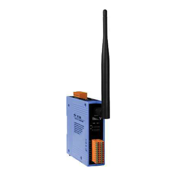
The WF-2000 front panel contains the antenna, I/O connectors and LEDs. RP SMA Connector Signal strength LED Indicator System Status Indicator I/O Connector I/O LED Indicator Figure 2-1: Front Panel of the WF-2000 WF-2000 Series Wi-Fi I/O User’s Manual (Ver. 1.0, Sep./2012) ------------- 11... - Page 12 Terminal No. Pin Assignment RL5 COM RL4 COM RL5 NO RL4 NO DI.COM RL3 COM RL3 NO RL2 COM RL2 NO RL1 COM RL1 NO RL0 COM DI.GND RL0 NO WF-2000 Series Wi-Fi I/O User’s Manual (Ver. 1.0, Sep./2012) ------------- 12...
-
Page 13: Top Panel
2000 firmware, the switch can be moved from the OP position to the FW position. Table 2-5: Power/Signal Connector Power/Signal connector Pin Assignment Description Frame Ground +10 ~ +30 VDC Power / RS-232 GND RS-232 RxD RS-232 TxD WF-2000 Series Wi-Fi I/O User’s Manual (Ver. 1.0, Sep./2012) ------------- 13... -
Page 14: Dimensions
The diagrams below provide the dimensions of the WF-2000 to use in defining your enclosure specifications. All dimensions are in millimeters. Figure 2-3: Front / Left Side dimension of the WF-2000 Figure 2-4: Top / Bottom dimension of the WF-2000 WF-2000 Series Wi-Fi I/O User’s Manual (Ver. 1.0, Sep./2012) ------------- 14... -
Page 15: Hardware Connection
The following figures describe the Power and the COM port to a serial device via serial network. Figure 2-5: Power and Serial port wire connection 2.4.2 I/O connection 2.4.2.1 WF-2055 I/O Wire Connection Figure 2-6: WF-2055 DI Dry contact wire connection WF-2000 Series Wi-Fi I/O User’s Manual (Ver. 1.0, Sep./2012) ------------- 15... - Page 16 ГК Атлант Инжиниринг – официальный представитель в РФ и СНГ +7(495)109-02-08 sales@bbrc.ru www.bbrc.ru Figure 2-7: WF-2055 DI Wet contact wire connection Figure 2-8: WF-2055 DO wire connection WF-2000 Series Wi-Fi I/O User’s Manual (Ver. 1.0, Sep./2012) ------------- 16...
- Page 17 ГК Атлант Инжиниринг – официальный представитель в РФ и СНГ +7(495)109-02-08 sales@bbrc.ru www.bbrc.ru 2.4.2.2 WF-2060 I/O Wire Connection Figure 2-9: DI Dry contact wire connection Figure 2-10: DI Wet contact wire connection WF-2000 Series Wi-Fi I/O User’s Manual (Ver. 1.0, Sep./2012) ------------- 17...
-
Page 18: Watchdog Timer Settings
Figure 2-6: Watchdog timer JP1 Jumper Position FW / OP Dip-switch On the top of the WF-2000 series module, there is a dip-switch used for firmware operation or firmware update of the module. The following steps show how to use this dip-switch. - Page 19 ГК Атлант Инжиниринг – официальный представитель в РФ и СНГ +7(495)109-02-08 sales@bbrc.ru www.bbrc.ru Figure 2-7: FW Position of Dip-Switch Figure 2-8: CA-0910 Cable Figure 2-9: Downloads cable connection WF-2000 Series Wi-Fi I/O User’s Manual (Ver. 1.0, Sep./2012) ------------- 19...
- Page 20 The result will be shown in “Firmware Update” field. Figure 2-10: WF-2055 firmware update process The WF-2055 firmware can be downloaded from ftp://ftp.icpdas.com/pub/cd/usbcd/napdos/wifi/io/wf-2055/firmware The Firmware_Update_Tool program can be downloaded from ftp://ftp.icpdas.com/pub/cd/usbcd/napdos/wifi/io/wf- 2055/software/tool/ WF-2000 Series Wi-Fi I/O User’s Manual (Ver. 1.0, Sep./2012) ------------- 20...
-
Page 21: Firmware Operation Mode
In the operation mode, users need to set the dip-switch to the “OP” position as Figure 2-11 and reset the power, and the WF-2000 can run in the operation mode. In this mode, user can use the WF-2000 series with a computer or with another WF-2000 series module for wireless connection. -
Page 22: Software
ГК Атлант Инжиниринг – официальный представитель в РФ и СНГ +7(495)109-02-08 sales@bbrc.ru www.bbrc.ru 3. Software This chapter explains how to uses the WF-2000 Utility to carry on the WF-2000 series wireless communication configuration Established TCP connection I/O control and I/O monitoring. -
Page 23: Wf-2000 I/O Utility
The following is the main screens provided by WF-2000 I/O Utility, this utility tool can be thought as a useful tool for I/O control and monitoring on the WF-2000 series. It supplies several functions, such as Wi-Fi configuration setting, module pair connection setting, and DO power on / safe value setting. - Page 24 Figure 3-2: WF-2000 I/O utility version information Main functional areas: [1] Connection Enter the WF-2000 series’ IP, and press the "Connect" button. WF-2000 I/O Utility will connect to the WF-2000 series. Figure 3-3: Connection setting area WF-2000 Series Wi-Fi I/O...
- Page 25 ГК Атлант Инжиниринг – официальный представитель в РФ и СНГ +7(495)109-02-08 sales@bbrc.ru www.bbrc.ru Connection Port Number Set WF-2000 I/O Utility connection port number and this setting must be the same with the WF-2000 series’ port number setting for normal connection. Figure 3-4: Connection port number setting area System Message This area will display information for the system connection.
- Page 26 The following figure shows the counter status of the WF-2000 DI module series. Users can click the "Reset" button to reset the counter value. Figure 3-10: DI counter dispaly area WF-2000 Series Wi-Fi I/O User’s Manual (Ver. 1.0, Sep./2012) ------------- 26...
-
Page 27: Basic Parameter Configuration
Figure 3-11: Basic Parameter Setting Interface Net ID The Unit Identifier in Modbus TCP/IP application data unit. (1~247, default:1) Net ID Setting Interface Figure 3-12: WF-2000 Series Wi-Fi I/O User’s Manual (Ver. 1.0, Sep./2012) ------------- 27... -
Page 28: Network Configuration
MAC Address Display Figure 3-13: : : : Network configuration Wi-Fi configuration Wi-Fi configuration interface of WF-2000 series is shown as below, such as Wi-Fi connection mode, SSID, WLK, WLCH, Encryption, and so forth. The detailed description is as the following table. -
Page 29: Parameter Transmission Interface
WPA2 Characters of key should be in range of: [0 ~ 9] or [A ~ F] or [a ~ f]. Ad-Hoc Mode: Ad-Hoc:Use Ad-Hoc connectivity with another WF-2000 series or Wi-Fi Wi-Fi Mode devices to create AD-hoc wireless network. Service Set Identifier: Connected devices must be with the same SSID, SSID SSID length must not exceed 20 characters. -
Page 30: Parameter Transmission Status Bar
Figure 3-17 Firmware version and Date created Parameter reading function WF-2000 I/O utility provides parameters download function for I- WF-2000 series by RS-232 and Wi-Fi interface. It allows user to download the parameters form WF-2000 series. Figure 3-18: Parameter reading button... -
Page 31: Exit Parameter Setting
WF-2000 modules can poll the status of remote input devices using the Modbus/TCP protocol and then continuously write to its output channels in the background. Figure 3-21: Pair connection settings screen WF-2000 Series Wi-Fi I/O User’s Manual (Ver. 1.0, Sep./2012) ------------- 31... - Page 32 DI base address of Remote DI device that will be mapped to local DO register. I/O Count: I/O count mapped from the base address. Communication Timeout: The period of which the WF-2000 series is waiting for a response from the remote DI device. WF-2000 Series Wi-Fi I/O User’s Manual (Ver. 1.0, Sep./2012) ------------- 32...
-
Page 33: Do Value Settings Screen
Click the “Action” button to enable the settings, and then click the “ON/OFF” radio box to set the power-on value or safe value. Finally, click the "Write Para." button to take the parameters effect. WF-2000 Series Wi-Fi I/O User’s Manual (Ver. 1.0, Sep./2012) ------------- 33... -
Page 34: Application Notes
+7(495)109-02-08 sales@bbrc.ru www.bbrc.ru 4. Application Notes In practice, users can use the two WF-2000 series or a set of WF- 2000 series module with the computer (with supporting for wireless network) connection structure in the application. It can complete the purpose of I/O control to wireless network by this way. -
Page 35: Hardware Installation
Step 1: Checking the WF-2000 series firmware operation mode It needs to set the DIP switch to the "OP" position (operating mode), as resetting the power, WF-2000 series will be in the operation mode. Step 2: Serial port connection WF-2000 series supports RS-232 serial communication. The circuit configuration is as shown in Figure 2-5. - Page 36 02、Port Number : This field is used to set TCP/IP port of connection according to the actual conditions. This case is set TCP/IP port as "502" in Figure 4-3. 03、Local IP : Set the local WF-2000 series' IP. Here set to "192.168.255.1". 04、Gateway : Gateway settings. Here set to "192.168.255.254".
-
Page 37: Pc Connection Configuration
Figure 4-5: Properties setting of wireless network connections b. Select the Internet Protocol (TCP/IP) and press the "Properties" button. Figure 4-6: Properties setting of Internet Protocol (TCP/IP) WF-2000 Series Wi-Fi I/O User’s Manual (Ver. 1.0, Sep./2012) ------------- 37... - Page 38 View available wireless networks and you can see the "WF- 2055" wireless network in the list. b. Select the "WF-2055" and press the "Connect" button. Figure 4-8: Wireless network connection WF-2000 Series Wi-Fi I/O User’s Manual (Ver. 1.0, Sep./2012) ------------- 38...
-
Page 39: Pc Connection Test
If the network settings are correct, this will immediately establish a connection. c. You can do the DO output control or DI / DO monitoring in this operation interface. WF-2000 Series Wi-Fi I/O User’s Manual (Ver. 1.0, Sep./2012) ------------- 39... - Page 40 If the network settings are correct, this will immediately establish a connection. c. Use the function code "0x0F", and set the reference number as "0x00" to do the DO output control. Figure 4-12: DO output control interface WF-2000 Series Wi-Fi I/O User’s Manual (Ver. 1.0, Sep./2012) ------------- 40...
- Page 41 Figure 4-13: DO output monitor interface e. Use the function code "0x02", and set the reference number as "0x00" to get the DI input monitor data. Figure 4-14: DI input monitor interface WF-2000 Series Wi-Fi I/O User’s Manual (Ver. 1.0, Sep./2012) ------------- 41...
-
Page 42: Pair Connection Test
08、Set the same WLK, here does not have the setting. 09、Set the same WLCH as "2". 10、Set the same Encryption, here set "NONE" (without encryption) 11、Finally, click the "Write Para." button to take the parameters effect. WF-2000 Series Wi-Fi I/O User’s Manual (Ver. 1.0, Sep./2012) ------------- 42... - Page 43 08、Set the communication Timeout as "3000" ms. 09、Set the I/O Pair Connection to "Enable". 11、Finally, click the "Write Para." button to take the parameters effect. Figure 4-17: Pair connection setting interface WF-2000 Series Wi-Fi I/O User’s Manual (Ver. 1.0, Sep./2012) ------------- 43...
- Page 44 02、The connection will established automatically after about 10 seconds. 03、If the DI of WF-2055_1 have been triggered, then the DO of WF- 2055_2 will automatically output. WF-2055_1 WF-2055_2 Figure 4-18: Pair connection architecture and setting interface WF-2000 Series Wi-Fi I/O User’s Manual (Ver. 1.0, Sep./2012) ------------- 44...
-
Page 45: Modbus Applications
The Modbus protocol defines a simple protocol data unit independent of the underlying communication layers. The mapping of Modbus protocol on network can introduce some additional fields on the application data unit. WF-2000 Series Wi-Fi I/O User’s Manual (Ver. 1.0, Sep./2012) ------------- 45... -
Page 46: Mbap
When a Modbus request is sent from a Modbus Client to a Server device the function code field tells the Server what kind of action to perform. WF-2000 Series Wi-Fi I/O User’s Manual (Ver. 1.0, Sep./2012) ------------- 46... -
Page 47: Data
ГК Атлант Инжиниринг – официальный представитель в РФ и СНГ +7(495)109-02-08 sales@bbrc.ru www.bbrc.ru The Modbus/TCP feature of WF-2000 series module supports 7 function codes, which allows the reading and writing of data contents of registers. Table 5-2: Supports Function Codes of WF-2000 series... -
Page 48: Data Encoding
01 and 02. Therefore, a single register contains 16 bits of binary data, each having a specific meaning. Table 5-3: A single register contains 16 bits of binary data Value 0xAA55 0xAA 0x55 (1010101001010101) (10101010) (01010101) WF-2000 Series Wi-Fi I/O User’s Manual (Ver. 1.0, Sep./2012) ------------- 48... - Page 49 Function code 03 and 04 read 16-bits items at a time; therefore, each of these data items will fit within one register that is read. Table 5-4: A 16-bits word item Value 0x1234 0x12 0x34 WF-2000 Series Wi-Fi I/O User’s Manual (Ver. 1.0, Sep./2012) ------------- 49...
-
Page 50: Address Mapping
(2 points/ Each (0x32) Channel) Table 5-8: (4xxxx) AO address Begin Address Points Descriptions Range Access Type 1= Reset System 247= Restore to Reset System (0xF7) Factory Default Settings WF-2000 Series Wi-Fi I/O User’s Manual (Ver. 1.0, Sep./2012) ------------- 50... -
Page 51: Wf-2060 I/O And Counter Address Mapping
(2 points/ Each (0x32) Channel) Table 5-12: (4xxxx) AO address Begin Address Points Descriptions Range Access Type 1= Reset System 247= Restore to Reset System (0xF7) Factory Default Settings WF-2000 Series Wi-Fi I/O User’s Manual (Ver. 1.0, Sep./2012) ------------- 51... -
Page 52: Troubleshooting
3. When the correct implementation of the above steps, the Signal Strength LEDs and PWR/Wi-Fi Step4 LEDS of the WF-2000 series should be turn on, and that should be turn off after 500 ms later. 4. Reset the power the WF-2000 series would back to factory defaults. - Page 53 ГК Атлант Инжиниринг – официальный представитель в РФ и СНГ +7(495)109-02-08 sales@bbrc.ru www.bbrc.ru Technical Support If you have problems about using the WF-2000 series I/O module please contact ICP DAS Product Support. Email: service@icpdas.com WF-2000 Series Wi-Fi I/O User’s Manual (Ver. 1.0, Sep./2012) ------------- 53...
Need help?
Do you have a question about the WF-2000 Series and is the answer not in the manual?
Questions and answers