
Related Manuals for ICP DAS USA WF-2015


Summary of Contents for ICP DAS USA WF-2015
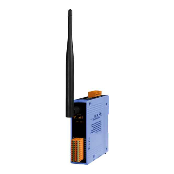
- Page 1 WF-2000 Series Wi-Fi I/O Module AIO User Manual www.icpdas.com WF-2000 Series AIO User’s Manual (RevB1.0, Oct./2016) ------------- 1...
- Page 2 Warranty All products manufactured by ICP DAS are under warranty regarding defective materials for a period of one year from the date of delivery to the original purchaser. Warning ICP DAS assumes no liability for damages resulting from the use of this product.
-
Page 3: Table Of Contents
Table of Contents 1. Introduction ..................5 Wireless connection mode ..............5 Features..................... 5 1.2.1 Features Description ................ 6 Specifications ..................7 2. Hardware ..................12 Front Panel ..................12 2.1.1 LED Indicator ................. 13 2.1.2 I/O Connector................. 13 Top Panel ..................16 Dimensions .................. - Page 4 5.2.4 Response ..................50 5.2.5 Data Encoding................51 Address Mapping ................52 5.3.1 WF-2015 I/O Address Mapping ............52 5.3.2 WF-2017 I/O Address Mapping ............52 5.3.3 WF-2019 I/O Address Mapping ............53 5.3.4 WF-2026 I/O Address Mapping ............53 6.
-
Page 5: Introduction
1. Introduction The WF-2000 RevB series I/O modules have WLAN connection complies with the IEEE802.11b/g/n standards. With the popularity of 802.11 network infrastructure, the WF-2000 RevB series I/O modules make an easy way to incorporate wireless connectivity into monitoring and control systems. They also support Modbus/TCP and UDP protocol and the network encryption configuration, which makes perfect integration to SCADA software and offer easy and safe access for users from anytime and anywhere. -
Page 6: Features Description
1.2.1 Features Description The WF-2000 module offers the most comprehensive configuration to meet specific application requirements. The following list shows the features designed to simplify installation, configuration and application. Compatible with IEEE 802.11b/g/n standards WF-2000 RevB module complied with IEEE 802.11b/g/n standard from 2.4~2.5 GHz, and it can be used to provide up to 11 Mbps for IEEE 802.11b, 54 Mbps for IEEE 802.11g and 72 Mbps for IEEE 802.11n to connect your wireless LAN. -
Page 7: Specifications
Module Watchdog is a built-in hardware circuit that monitors the operating status of the module and will reset the module if a failure occurs in the hardware or the software. Specifications Table 1-1 System Specifications Modules WF-2015 WF-2017 WF-2019 WF-2026 Wi-Fi Interface Antenna... - Page 8 Table 1-2 WF-2015 I/O Specification Modules WF-2015 Analog Input Channels Input Type 2/3-wire RTD RTD Type Pt100, Pt1000, Ni120, Cu50, Cu100, Cu1000 Resolution 16 bit Accuracy ±0.05% of FSR Zero Drift 0.5 µV/°C Span Drift 20 µV/°C Sampling Rate 12 Hz (Total)
- Page 9 Table 1-3 WF-2017 I/O Specification Modules WF-2017 Analog Input Channels 8-ch Differential / 16-ch Single-ended(Note), Jumper Selectable Voltage : ±150 mV, ±500 mV, ±1 V, ±5 V, ±10 V Input Type Current : 0 ~ +20 mA, +4 ~ +20 mA, ±20 mA (Jumper Selectable) Resolution 16 bit Accuracy...
- Page 10 Table 1-4 WF-2019 I/O Specification Modules WF-2019 Analog Input Channels Voltage : ±15 mV, ±50 mV, ±100 mV, ±500 mV, ±1 V, ±2.5 V, ±5 V, ±10 V Input Type Current : ±20 mA (External resistor is required) Thermocouple : J, K, T, E, R, S, B, N, C Resolution 16 bit Accuracy...
- Page 11 Table 1-5 WF-2026 I/O Specification Modules WF-2026 Analog Input Channels Wiring Differential Voltage ±150 mVDC, ±500 mVDC, ±1 VDC, ±5 VDC, ±10 VDC Input Range Current 0 ~ +20 mA, +4 ~ +20 mA, ±20 mA (Jumper Selectable) Resolution 16 bit Accuracy ±0.1% FSR Sampling Rate...
-
Page 12: Hardware
2.Hardware 2.1 Front Panel The WF-2000 AIO modules front panel contains the antenna, I/O connectors and LEDs. RP SMA Connector Signal strength System Status I/O Connector Figure 2-1 Front Panel of the WF-2000 AIO modules WF-2000 Series AIO User’s Manual (RevB1.0, Oct./2016) ------------- 12... -
Page 13: Led Indicator
Table 2-2 Signal Strength LED Indicator Signal Strength LED Indicator LED Status Signal strength High Medium Bad or No Signal 2.1.2 I/O Connector 2.1.2.1 WF-2015 Figure 2-2 I/O Connector of WF-2015 WF-2000 Series AIO User’s Manual (RevB1.0, Oct./2016) ------------- 13... - Page 14 2.1.2.2 WF-2017 Figure 2-3 I/O Connector of WF-2017 2.1.2.3 WF-2019 Figure 2-4 I/O Connector of WF-2019 WF-2000 Series AIO User’s Manual (RevB1.0, Oct./2016) ------------- 14...
- Page 15 Figure 2-5 Pin Assignment of DB-1820 2.1.2.4 WF-2026 Figure 2-6 I/O Connector of WF-2026 WF-2000 Series AIO User’s Manual (RevB1.0, Oct./2016) ------------- 15...
-
Page 16: Top Panel
2.2 Top Panel The WF-2000 top panel contains the Power/Signal connector and operating mode Selector switch. Power/RS-232 Operating Mode Connector Selector Switch Figure 2-3 Top Panel of the WF-2000 Operating Mode Selector Switch FW mode: Firmware update mode Move the switch to the OP position after the upgrade is complete. OP mode: Firmware operation mode In the WF-2000, the switch is always in the OP position. -
Page 17: Dimensions
The diagrams below provide the dimensions of the WF-2000 to use in defining your enclosure specifications. All dimensions are in millimeters. Figure 2-4 Front / Left Side dimension of the WF-2015/WF-2017/WF-2026 Figure 2-5 Front / Left Side dimension of the WF-2019 WF-2000 Series AIO User’s Manual (RevB1.0, Oct./2016) ------------- 17... -
Page 18: Hardware Connection
Figure 2-6 Top / Bottom dimension of the WF-2015/WF-2017/WF-2026 Figure 2-7 Top / Bottom dimension of the WF-2019 Hardware Connection 2.4.1 Power and Serial port connection The following figures describe the Power and the COM port to a serial device via serial network. -
Page 19: I/O Connection
Figure 2-8 Power and Serial port wire connection 2.4.2 I/O connection 2.4.2.1 WF-2015 Figure 2-9 AI wire connection of WF-2015 WF-2000 Series AIO User’s Manual (RevB1.0, Oct./2016) ------------- 19... - Page 20 2.4.2.2 WF-2017 Figure 2-13 AI wire connection of WF-2017 2.4.2.3 WF-2019 Figure 2-14 AI wire connection of WF-2019 WF-2000 Series AIO User’s Manual (RevB1.0, Oct./2016) ------------- 20...
- Page 21 2.4.2.4 WF-2026 Figure 2-15 AIO wire connection of WF-2026 Figure 2-16 DIO wire connection of WF-2026 WF-2000 Series AIO User’s Manual (RevB1.0, Oct./2016) ------------- 21...
-
Page 22: Jumper Settings
2000 cover and use the Jumper to activate the WDT built in the module, as the Figure 2-13. Note that the default setting is active. Table 2-4 WDT Jumper Position Mode Jumper Number WF-2015 WF-2017 WF-2019 WF-2026 Enable (default) Disable Figure 2-10 Watchdog timer Jumper Position 2.5.2 AI Settings... -
Page 23: Fw / Op Dip-Switch
Table 2-6 WF-2026 Analog Input/Output Type Jumper configuration Output Type Jumper Position Input Type Jumper Position Modules Voltage Voltage WF-2026 Current Current FW / OP Dip-switch On the top of the WF-2000 series module, there is a dip-switch used for firmware operation or firmware update of the module. The following steps show how to use this dip-switch. - Page 24 Figure 2-12 CA-0910 Cable Figure 2-13 Downloads cable connection Users just need to execute “Firmware_Update_Tool.exe” and follow the below steps to complete the firmware updating process. [1] Choose “COM” interface and “COM Port”. [2] Click “Browser” button to choose firmware file. (e.g. WF20xx.fw) [3] Click “Firmware Update”...
-
Page 25: Firmware Operation Mode
The result will be shown in “Firmware Update” field. Figure 2-14 WF-2000 firmware update process The WF-2000 firmware can be downloaded from ftp://ftp.icpdas.com/pub/cd/usbcd/napdos/wifi/io/wf-20xx/firmware The Firmware_Update_Tool program can be downloaded from ftp://ftp.icpdas.com/pub/cd/usbcd/napdos/wifi/io/wf- 20xx/software/tool/ 2.6.2 Firmware Operation Mode In the operation mode, users need to set the dip-switch to the “OP” position as Figure 2-22 and reset the power, and the WF-2000 can run in operation mode. - Page 26 Figure 2-15 OP Position of Dip-Switch WF-2000 Series AIO User’s Manual (RevB1.0, Oct./2016) ------------- 26...
-
Page 27: Software
Microsoft Windows XP, Vista and 7 (.NET framework 4.0 is required). You can download this program from: ftp://ftp.icpdas.com/pub/cd/usbcd/napdos/wifi/wf-2015/software/utility/ The WF IO Utility (RevB) is designed for "WF-2000 RevB" series only, not for "WF-2000" series (without "RevB" mark). Make sure there is a "RevB"... -
Page 28: Main Screen
3.1.1 Main Screen Figure 3-1 WF IO Utility (RevB1.0 or later) main screen Menu Function: [1] File Exit Press this button to exit WF-2000 I/O Utility. [2] Device Connection Search This function can search all of WF-2000 devices that support UDP search communication. -
Page 29: Configuration Screen
name, IP address, Mask, Gateway, MAC address, Modbus Net ID and its DHCP state. 3.1.2 Configuration Screen Figure 3-2 WF IO Utility (RevB1.0 or later) configuration screen [1] Network Net ID The Unit Identifier in Modbus TCP/IP application data unit. (Range:1~247, Default:1) DHCP Enable If a DHCP server is present on the network, the WF-2000 will... - Page 30 Gateway WF-2000 Gateway setting (Default: 192.168.255.254) MAC Address WF-2000 MAC Address display DHCP Server Enable This function is used to start/stop the DHCP server, prior to starting the server, the adapter should be configured with a valid static IP address, both Start IP address and Gateway should be same and created or configure to create a limited AP network Start IP Addr.
- Page 31 Wi-Fi Configuration Table 3-1: Infrastructure Mode Infrastructure : Use the wireless access point way for connection and Wi-Fi Mode transmission. (Must have Wi-Fi AP) Service Set Identifier: Connected devices must be with the same SSID, SSID SSID length must not exceed 20 characters. 0~11:Wi-Fi transmission channel setting, connected devices must with the Wireless CH same channel.
-
Page 32: Analog Input Screen
Auto Disconnect Once the connection is established, if there is no data exchange within 60 sec the socket will be closed automatically when the this function is enabled Communication Net ID Modbus Net ID of WF-2000 Parameter Transmission Interface The parameter transmission interface, that provides wireless and RS-232 interface for connection. - Page 33 Configuration Region Data Monitor Region Configuration Region Message Region Figure 3-4 WF-2015 diagnostic screen Data Monitor Region Configuration Region Message Region Figure 3-5 WF-2017 diagnostic screen WF-2000 Series AIO User’s Manual (RevB1.0, Oct./2016) ------------- 33...
- Page 34 Configuration Region Data Monitor Region Message Region Figure 3-6 WF-2019 diagnostic screen Data Monitor and Control Region Configuration Region Configuration Region Message Region Figure 3-7 WF-2026 diagnostic screen WF-2000 Series AIO User’s Manual (RevB1.0, Oct./2016) ------------- 34...
- Page 35 Configuration Region All I/O related configurations can be set in this region. This region is divided into two parts, channel and module related setting. The channel related setting is in the "Selected Channel". The rest are module related settings. Set All All AI or AO channels related setting will follow current selection.
- Page 36 Enable / Disable the open-wire detection for thermocouple. CJC Enable Enable / Disable the CJC (Cold-Junction Compensation). CJC Offset Setting the CJC offset value for all AI channels. The offset value is used to add or subtract the reading value. Changing of this value will not affect calibration, but will affect the reading value of temperature type.
- Page 37 Monitor Region The I/O related data and configurations will be listed here. Users can select the channel to configure in the “I/O Monitor Region”. The setting of this selected channel will show in “I/O configuration region”. Message Region This area will display information for the system connection. Control Region In the controlling region, the real-time value and module configuration can be read or written in this page.
- Page 38 Safe Value of DO The safe value of DO can be Set and Get in this region. When the communication timeout occurs, the "Safe Value" is loaded into the DO. Enable: Enabled or disabled this function. Set Value: Set the current output status as Safe Value. Get Value: Get the current configuration of Safe Value.
- Page 39 Enable: Select which channel to enable or disable this function. Set Value: Set the current output value as Safe Value. Get Value: Get the current configuration of Safe Value. Active Time (ms): This function is active when the communication timeout reach this setting. WF-2000 Series AIO User’s Manual (RevB1.0, Oct./2016) ------------- 39...
-
Page 40: Application Notes
4. Application Notes Users can use a computer to communicate with the WF-2000 devices in the application. It can complete the purpose of I/O control to wireless network by this way. Figure 4-1 WF-2000 application architecture 4.1 Hardware Installation Before use, associated hardware configuration, the steps described as follows:... -
Page 41: Wf-2000 Series Configuration
If you do not need parameter setting, this step can be omitted. Step 3: Power connection Connect the power supply to WF-2000 series' power terminator, as shown in Figure 2-5. 4.2 WF-2000 series Configuration 4.2.1 WF-2000 Series Wireless Network Configuration Figure 4-2 Configuration Interface 01、Net ID : The Unit Identifier in Modbus TCP/IP application data unit. -
Page 42: Pc Connection Configuration
12、Upload parameters : After completing the settings above, select the "RS-232" interface, communication "Net ID" and "COM Num". Press "Write Parameter" button to upload the parameters. 4.2.2 PC Connection Configuration 01、TCP/IP Setting : a. Open Network connections and entry the properties setting of wireless network connections. - Page 43 c. Configuring your computer to "Obtain an IP address automatically" allows WF-2000 module to assign a dynamic IP address to it. Once the wireless network connection is successful, the computer will obtain an IP address as "192.168.255.100". Figure 4-5 IP address setting interface 02、Wireless network connection : a.
-
Page 44: Access I/O Data
c. Press the "Connect Anyway" button for the next step. Figure 4-7 Connection confirm interface d. After waiting for a while, there will appear connection success screen. Figure 4-8 Connection successful interface 4.2.3 Access I/O data 01、Connection with WF I/O utility (RevB1.0 or later) a. - Page 45 Then you will see the I/O page come out. In the I/O page, it is used to access I/O data and configure parameters. Figure 4-11 I/O page interface(WF-2015) 02、Connection with Modbus TCP utility a. Open Modbus TCP utility and key in the IP address as "192.168.255.1", Port as "502".
- Page 46 Table 4-1 Modbus request command list FC1 Read FC2 Read FC3 Read FC4 Read FC16 Write FC15 Force multiple coils multiple input multiple multiple input multiple Request multiple coils status (0xxxx) for discrete (1xxxx) registers registers registers (0xxxx) for DO for DI (4xxxx) for AO (3xxxx) for AI...
- Page 47 Figure 4-18 Write multiple registers (4xxxx) for AO WF-2000 Series AIO User’s Manual (RevB1.0, Oct./2016) ------------- 47...
-
Page 48: Modbus Applications
5. Modbus Applications The WF-2000 is a Modbus device that allows you to access terminals data via Wi-Fi and communicates using a master-slave technique in which only one device (the master) can initiate transactions (called queries). The other devices (slaves) respond by supplying the requested data to the master, or by taking the action requested in the query. -
Page 49: Mbap
Modbus/TCP Application Data Unit Transaction ID Protocol ID Length Unit ID FCode Data (2 bytes) (2 bytes) (2 bytes) (1 bytes) (1 bytes) (0 to 252 bytes) MBAP Header Protocol Data Unit Figure 5-1 Modbus/TCP Application Data Unit 5.2.1 MBAP The Modbus/TCP extension includes 7 additional bytes to the original Modbus protocol, which allows for transport over the TCP/IP layers. -
Page 50: Data
Table 5-2 Supports Function Codes of WF-2000 series Function Code Descriptions 01 (0x01) Read Coil Status 02 (0x02) Read Input Status 03 (0x03) Read Holding Registers 04 (0x04) Read Input Registers 05 (0x05) Force Single Coil 15 (0x0F) Force Multiple Coils 16 (0x10) Preset Multiple Registers Any other function code request will be returned with an error... -
Page 51: Data Encoding
For example a client can read the ON/OFF states of a group of digital input or output or it can read/write the data contents of a group of registers. When the server responds to the client, it uses the function code field to indicate either a normal response or that some kind of error occurred (called an exception response). -
Page 52: Address Mapping
Table 5-4 A 16-bits word item Value 0x1234 0x12 0x34 5.3 Address Mapping 5.3.1 WF-2015 I/O Address Mapping Table 5-5 (3xxxx) AI address Begin Address Points Descriptions Range Access Type 30001 Analog Input -32768 ~ +32767 (Bipolar) Table 5-6 (4xxxx) AO address... -
Page 53: Wf-2019 I/O Address Mapping
Table 5-8 (4xxxx) AO address Begin Address Points Descriptions Range Access Type 1= Reset System 40248 Reset System 247= Restore to Factory Default Settings 5.3.3 WF-2019 I/O Address Mapping Table 5-9 (3xxxx) AI address Begin Address Points Descriptions Range Access Type -32768 ~ +32767 (Bipolar) 30001 1~10... - Page 54 Table 5-13 (4xxxx) AO address Begin Address Points Descriptions Range Access Type 1= Reset System 40248 Reset System 247= Restore to Factory Default Settings Table 5-14 (0xxxx) DO address Begin Address Points Descriptions Range Access Type 00001 Digital Output 0=OFF, 1=ON Table 5-15 (1xxxx) DI address Begin Address Points...
-
Page 55: Troubleshooting
6. Troubleshooting Item Problem Description Solution Power Failure 1. Please return to the ICP DAS for inspection and (PWR LED Off) repair 1. Make sure that the service set identifier device (SSID) settings are the same. 2. Make sure Wi-Fi transmission Channel settings are the same. - Page 56 Item Problem Description Solution Cannot execute WF Because the ICP DAS WF Utility(RevB1.0 or later) Utility(RevB1.0 or later) with requires .NET Framework v4.0,this program will the message like the automatically detect the .NET Framework v4.0 following installed as well or not. Users can install .NET Figure 6-1 Framework v4.0 in the following website.
-
Page 57: Analog Input Type And Data Format Table
Appendix A. A.1 Analog Input Type and Data Format Table Type Code Input Range Data Format +F.S -F.S Engineering Unit +15.000 -15.000 -15 to +15 mA 2’s comp HEX 7FFF 8000 Engineering Unit +50.000 -50.000 -50 to +50 mA 2’s comp HEX 7FFF 8000 Engineering Unit... - Page 58 Type Code Data Format +F.S -F.S Input Range Engineering Unit +1.0000 -1.0000 -1 to +1 V 2’s comp HEX 7FFF 8000 Engineering Unit +500.00 -500.00 -500 to +500 mV 2’s comp HEX 7FFF 8000 Engineering Unit +150.00 -150.00 -150 to +150 mV 2’s comp HEX 7FFF 8000...
-
Page 59: Analog Output Type And Data Format Table
Type Code Data Format +F.S -F.S Input Range Type N Engineering Unit +1300.0 -0270.0 Thermocouple 2’s comp HEX 7FFF E56B -270 to 1300°C Type C Engineering Unit +2320.0 +0000.0 Thermocouple 2’s comp HEX 7FFF 0000 0 to 2320°C Engineering Unit +20.000 +00.000 0 to +20 mA... -
Page 60: Cjc (Cold Junction Compensation) Definition
A.3 CJC (cold junction compensation) Definition Type Input Range Data Format +F.S -F.S Engineering Unit +100.00 -030.00 -30 to +100 ℃ 2’s comp HEX 03E8 FED4 A.4 RTD Input Type and Data Format Table Type Code Input Range Data Format +F.S -F.S Engineering unit... - Page 61 Engineering unit +100.00 -080.00 Nickel 120 2’s comp HEX 7FFF 999A -80 ~ 100°C +200.64 +066.60 Engineering unit +100.00 +000.00 Nickel 120 2’s comp HEX 7FFF 0000 0 ~ 100°C +200.64 +120.60 Engineering unit +600.00 -200.00 Platinum 1000 2’s comp HEX 7FFF D556 α= 0.00385...
Need help?
Do you have a question about the WF-2015 and is the answer not in the manual?
Questions and answers