
Related Manuals for ICP DAS USA WF-2019/S


Summary of Contents for ICP DAS USA WF-2019/S
- Page 1 WF-2000 Series Wi-Fi I/O Module AIO User’s Manual www.icpdas.com WF-2000 Series AIO User’s Manual (Ver. 1.1, Mar./2014) ------------- 1...
- Page 2 Warranty All products manufactured by ICP DAS are under warranty regarding defective materials for a period of one year from the date of delivery to the original purchaser. Warning ICP DAS assumes no liability for damages resulting from the use of this product.
-
Page 3: Table Of Contents
Table of Contents 1. Introduction ..................5 Wireless connection mode ..............5 Features..................... 5 1.2.1 Features Description ................ 6 Specifications ..................7 2. Hardware ..................10 Front Panel ..................10 2.1.1 LED Indicator ..................11 2.1.2 I/O Connector..................11 Top Panel ..................13 Dimensions ..................14 Hardware Connection .............. - Page 4 5.2.4 Response ..................39 5.2.5 Data Encoding................40 Address Mapping ................41 5.3.1 WF-2017 I/O Address Mapping ............41 5.3.2 WF-2019 I/O Address Mapping ............42 6. Troubleshooting................43 Appendix A....................45 A.1 Analog Input Type and Data Format Table ............ 45 A.2 CJC (cold junction compensation) Definition..........
-
Page 5: Introduction
1. Introduction The WF-2000 series I/O modules have WLAN connection complies with the IEEE802.11b/g standards. With the popularity of 802.11 network infrastructure, the WF-2000 series I/O modules make an easy way to incorporate wireless connectivity into monitoring and control systems. They also support Modbus/TCP and UDP protocol and the network encryption configuration, which makes perfect integration to SCADA software and offer easy and safe access for users from anytime and... -
Page 6: Features Description
1.2.1 Features Description The WF-2000 module offers the most comprehensive configuration to meet specific application requirements. The following list shows the features designed to simplify installation, configuration and application. Compatible with IEEE 802.11b/g standards WF-2000 module complied with IEEE 802.11b/g standard from 2.4~2.5GHz, and it can be used to provide up to 11Mbps for IEEE 802.11b and 54Mbps for 2.4GHz IEEE 802.11g to connect your wireless LAN. -
Page 7: Specifications
Built-in Multi-function I/O Various I/O components are mixed with multiple channels in a single module, which provides the most cost effective I/O usage and enhances performance of the I/O operations. Built-in Watchdog Module Watchdog is a built-in hardware circuit that monitors the operating status of the module and will reset the module if a failure occurs in the hardware or the software. - Page 8 Table 1-2: WF-2017 I/O Specification Modules WF-2017 Analog Input Channels 8-ch Differential / 16-ch Single-ended(Note), Jumper Selectable Voltage : ±150 mV, ±500 mV, ±1 V, ±5 V, ±10 V Input Type Current : 0 ~ +20 mA, +4 ~ +20 mA, ±20 mA (Jumper Selectable) Resolution 16 bit Accuracy...
- Page 9 Table 1-3: WF-2019 I/O Specification Modules WF-2019 Analog Input Channels Voltage : ±15 mV, ±50 mV, ±100 mV, ±500 mV, ±1 V, ±2.5 V, ±5 V, ±10 V Input Type Current : ±20 mA (External resistor is required) Thermocouple : J, K, T, E, R, S, B, N, C Resolution 16 bit Accuracy...
-
Page 10: Hardware
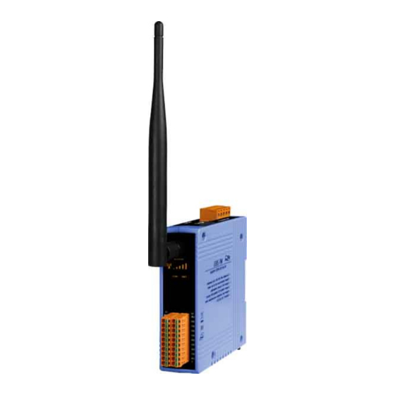
2. Hardware 2.1 Front Panel The WF-2000(AIO) front panel contains the antenna, I/O connectors and LEDs. RP SMA Connector Signal strength System Status I/O Connector Figure 2-1: Front Panel of the WF-2000(AIO) WF-2000 Series AIO User’s Manual (Ver. 1.1, Mar./2014) ------------- 10... -
Page 11: Led Indicator
2.1.1 LED Indicator Table 2-1: System Status Indicator System Status Indicator Module Status LED Status Wi-Fi communication error Blink per 100 ms Wi-Fi associate error Every 1 second flashes twice per 100 ms Wi-Fi unable to connect error Blink per 1000 ms Every 1 second flashes three times per Wi-Fi network configurations error 100 ms... - Page 12 2.1.2.2 WF-2019 Figure 2-3: I/O Connector of WF-2019 Figure 2-4: Pin Assignment of DB-1820 WF-2000 Series AIO User’s Manual (Ver. 1.1, Mar./2014) ------------- 12...
-
Page 13: Top Panel
2.2 Top Panel The WF-2000 top panel contains the Power/Signal connector and operating mode Selector switch. Power/RS-232 Operating Mode Connector Selector Switch Figure 2-5: Top Panel of the WF-2000 Operating Mode Selector Switch FW mode: Firmware update mode Move the switch to the OP position after the upgrade is complete. OP mode: Firmware operation mode In the WF-2000, the switch is always in the OP position. -
Page 14: Dimensions
Dimensions The diagrams below provide the dimensions of the WF-2000 to use in defining your enclosure specifications. All dimensions are in millimeters. Figure 2-6: Front / Left Side dimension of the WF-2017 Figure 2-7: Front / Left Side dimension of the WF-2019 WF-2000 Series AIO User’s Manual (Ver. - Page 15 Figure 2-8: Top / Bottom dimension of the WF-2017 Figure 2-9: Top / Bottom dimension of the WF-2019 WF-2000 Series AIO User’s Manual (Ver. 1.1, Mar./2014) ------------- 15...
-
Page 16: Hardware Connection
Hardware Connection 2.4.1 Power and Serial port connection The following figures describe the Power and the COM port to a serial device via serial network. Figure 2-10: Power and Serial port wire connection 2.4.2 I/O connection 2.4.2.1 WF-2017 Figure 2-11: AI wire connection of WF-2017 WF-2000 Series AIO User’s Manual (Ver. - Page 17 2.4.2.2 WF-2019 Figure 2-12: AI wire connection of WF-2019 WF-2000 Series AIO User’s Manual (Ver. 1.1, Mar./2014) ------------- 17...
-
Page 18: Jumper Settings
Jumper Settings 2.5.1 Watchdog Timer Settings A watchdog timer (WDT) is a device that performs a specific operation after a certain period of time if something goes wrong and the system does not recover on its own. A watchdog timer can perform a warm boot(restarting the system) after a certain number of milliseconds. -
Page 19: Fw / Op Dip-Switch
FW / OP Dip-switch On the top of the WF-2000 series module, there is a dip-switch used for firmware operation or firmware update of the module. The following steps show how to use this dip-switch. 2.6.1 Firmware Update Mode Please set the dip-switch to the “FW” position as Figure 2-7, and then the WF-2000 series will work in the “Firmware Update Mode”... - Page 20 Figure 2-20: Downloads cable connection Users just need to execute “Firmware_Update_Tool.exe” and follow the below steps to complete the firmware updating process. [1] Choose “COM” interface and “COM Port”. [2] Click “Browser” button to choose firmware file. (e.g. WF20xx.fw) [3] Click “Firmware Update” button to start firmware updating process. The result will be shown in “Firmware Update”...
-
Page 21: Firmware Operation Mode
Figure 2-21: WF-2000 firmware update process The WF-2000 firmware can be downloaded from ftp://ftp.icpdas.com/pub/cd/usbcd/napdos/wifi/io/wf-20xx/firmware The Firmware_Update_Tool program can be downloaded from ftp://ftp.icpdas.com/pub/cd/usbcd/napdos/wifi/io/wf- 20xx/software/tool/ 2.6.2 Firmware Operation Mode In the operation mode, users need to set the dip-switch to the “OP” position as Figure 2-22 and reset the power, and the WF-2000 can run in the operation mode. - Page 22 Figure 2-22: OP Position of Dip-Switch WF-2000 Series AIO User’s Manual (Ver. 1.1, Mar./2014) ------------- 22...
-
Page 23: Software
3. Software The WF-2000 Utility provides a simple way to test and acquire data easily and instantly for all ICP DAS WF-2000 series I/O modules without programming. WF-2000 Utility can be used to configure the wireless network interface, establish a TCP connection, I/O control and I/O monitoring of WF-2000 series I/O modules. -
Page 24: Configuration Screen
Menu Function: [1] File Exit Press this button to exit WF-2000 I/O Utility. [2] Device Search This function can search all of WF-2000 devices that support UDP communication. Configuration This function can enter the basic wireless configuration interface, as shown in Figure 3-2. [3] Search List Search list provides each item that scans from UDP and display the related information about the device, includes host name, alias... - Page 25 [1] Network Net ID The Unit Identifier in Modbus TCP/IP application data unit. (Range:1~247, Default:1) DHCP Enable If a DHCP server is present on the network, the WF-2000 will automatically obtain the network settings from the DHCP server when the DHCP function is enabled. (Ad Hoc mode don't support DHCP configuration) IP Address WF-2000 IP setting (Default:192.168.255.1)
- Page 26 Figure 3-3: Auto search SSID list Wi-Fi Modes Table 3-1: AP Mode Configuration AP:Use the wireless access point way for connection and transmission. Wi-Fi Mode (Must have Wi-Fi AP) Service Set Identifier: Connected devices must be with the same SSID, SSID SSID length must not exceed 20 characters.
- Page 27 [3] General F/W Version Display the firmware version of the WF-2000 Date created Display the date created of the WF-2000 Auto Disconnect Once the connection is established, if there is no data exchange within 60 sec the socket will be closed automatically when the this function is enabled Communication Net ID Modbus Net ID of WF-2000...
-
Page 28: Analog Input Screen
3.1.3 Analog Input Screen In the I/O page of the AI, the real-time value and module configuration can be read or written in this page. The detail of all items in this form will be introduced in this section. Monitor Region Configuration Region Message Region Polling Interval... - Page 29 Table 3-3: Signal Strength Information Display Table Signal Strength LED Indicator LED Status RSSI value Signal strength 1 ~ 40 High 41 ~ 60 Medium 61 ~ 80 Bad or No Signal Monitor Region The I/O related data and configurations will be listed here. Users can select the channel to configure in the “I/O Monitor Region”.
- Page 30 Channel CJC Offset Setting the CJC offset for the specific channel. The behavior of the setting is the same as the CJC Offset, but it only affects specific channel. Note: The CJC offset can be any in the range of -30.00 to +100.00 °C.
-
Page 31: Application Notes
4. Application Notes Users can use a computer to communicate with the WF-2000 devices in the application. It can complete the purpose of I/O control to wireless network by this way. Figure 4-1: WF-2019 + Laptop application architecture 4.1 Hardware Installation Before use, associated hardware configuration, the steps described as follows:... -
Page 32: Wf-2000 Series Configuration
shown in Figure 2-5. 4.2 WF-2000 series Configuration 4.2.1 WF-2000 Series Wireless Network Configuration Figure 4-3: Configuration Interface 01、Net ID : The Unit Identifier in Modbus TCP/IP application data unit. This case is set as "1" in Figure 4-3. 02、IP Address : Set the local WF-2000 series' IP. Here set to "192.168.255.1". -
Page 33: Pc Connection Configuration
4.2.2 PC Connection Configuration 01、TCP/IP Setting : a. Open Network connections and entry the properties setting of wireless network connections. Figure 4-4: Properties setting of wireless network connections b. Select the Internet Protocol (TCP/IP) and press the "Properties" button. Figure 4-5: Properties setting of Internet Protocol (TCP/IP) WF-2000 Series AIO User’s Manual (Ver. - Page 34 c. Click the "Use the following IP address" and entry the IP address as "192.168.255.10", Subnet mask as "255.255.255. 0". Finally, press "OK" button. Figure 4-6: IP address setting interface 02、Wireless network connection : a. View available wireless networks and you can see the "WF- 20xx"...
-
Page 35: Access I/O Data
c. Press the "Connect Anyway" button for the next step. Figure 4-8: Connection confirm interface d. After waiting for a while, there will appear connection success screen. Figure 4-9: Connection successful interface 4.2.3 Access I/O data 01、Connection with WF-2000 I/O utility (v2.0 or later) a. - Page 36 c. Then you will see the I/O page come out. In the I/O page, it is used to access I/O data and configure parameters. Figure 4-11: I/O page interface 02、Connection with Modbus TCP utility a. Open Modbus TCP utility and key in the IP address as "192.168.255.1", Port as "502".
-
Page 37: Modbus Applications
5. Modbus Applications The WF-2000 is a Modbus device that allows you to access terminals data via Wi-Fi and communicates using a master-slave technique in which only one device (the master) can initiate transactions (called queries). The other devices (slaves) respond by supplying the requested data to the master, or by taking the action requested in the query. -
Page 38: Mbap
Modbus/TCP Application Data Unit Transaction ID Protocol ID Length Unit ID FCode Data (2 bytes) (2 bytes) (2 bytes) (1 bytes) (1 bytes) (0 to 252 bytes) MBAP Header Protocol Data Unit Figure 5-1: Modbus/TCP Application Data Unit 5.2.1 MBAP The Modbus/TCP extension includes 7 additional bytes to the original Modbus protocol, which allows for transport over the TCP/IP layers. -
Page 39: Data
registers. Table 5-2: Supports Function Codes of WF-2000 series Function Code Descriptions 01 (0x01) Read Coil Status 02 (0x02) Read Input Status 03 (0x03) Read Holding Registers 04 (0x04) Read Input Registers 05 (0x05) Force Single Coil 15 (0x0F) Force Multiple Coils 16 (0x10) Preset Multiple Registers Any other function code request will be returned with an error... -
Page 40: Data Encoding
contains an exception code that the server application can use to determine the next action to be taken. For example a client can read the ON/OFF states of a group of digital input or output or it can read/write the data contents of a group of registers. -
Page 41: Address Mapping
5.2.5.2 16-bits Word A 16-bits word item is transmitted with the most significant byte first. Function code 03 and 04 read 16-bits items at a time; therefore, each of these data items will fit within one register that is read. Table 5-4: A 16-bits word item Value 0x1234... -
Page 42: Wf-2019 I/O Address Mapping
5.3.2 WF-2019 I/O Address Mapping Table 5-6: (3xxxx) AI address Begin Address Points Descriptions Range Access Type 30001 Analog Input -32768 ~ +32767 (0x0) 30010 CJC data -32768 ~ +32767 (0xA) Table 5-7: (4xxxx) AO address Begin Address Points Descriptions Range Access Type 1= Reset System... -
Page 43: Troubleshooting
6. Troubleshooting Item Problem Description Solution Power Failure 1. Please return to the ICP DAS for inspection and (PWR LED Off) repair 1. Make sure that the service set identifier device (SSID) settings are the same. 2. Make sure Wi-Fi transmission Channel settings are the same. - Page 44 Item Problem Description Solution Cannot execute WF-2000 Because the ICP DAS WF-2000 Utility(v2.0 or later) Utility(v2.0 or later) with the requires .NET Framework v4.0,this program will message like the following automatically detect the .NET Framework v4.0 Figure 6-1 installed as well or not. Users can install .NET Framework v4.0 in the following website.
-
Page 45: Analog Input Type And Data Format Table
Appendix A. A.1 Analog Input Type and Data Format Table Type Code Input Range Data Format +F.S -F.S Engineering Unit -15 ~ +15 mA 2’s comp HEX 7FFFh 8000h Engineering Unit -50 ~ +50 mA 2’s comp HEX 7FFFh 8000h Engineering Unit +100 -100... - Page 46 Type Code Data Format +F.S -F.S Input Range Engineering Unit -1 ~ +1 V 2’s comp HEX 7FFFh 8000h Engineering Unit +500 -500 -500 ~ +500 mV 2’s comp HEX 7FFFh 8000h Engineering Unit +150 -150 -150 ~ +150 mV 2’s comp HEX 7FFFh 8000h...
-
Page 47: Cjc (Cold Junction Compensation) Definition
Type Code Data Format +F.S -F.S Input Range Thermocouple 2’s comp HEX 7FFFh E56Bh -270 ~ 1300°C Type C Engineering Unit +2320 Thermocouple 2’s comp HEX 7FFFh 0000h 0 ~ 2320°C Engineering Unit 0 ~ +20 mA 2’s comp HEX FFFFh 0000h Note:...
Need help?
Do you have a question about the WF-2019/S and is the answer not in the manual?
Questions and answers