Table of Contents
Advertisement
Quick Links
MANUAL
DIP-1C
Varifan
OPENING
CLOSING
MANUAL
73
Installation / User's Guide
ATTENTION ELECTRICIAN
SEE WIRING DETAILS ON PAGES A-3 TO A-6 AND
ADDITIONAL INFORMATION IN SECTION B
®
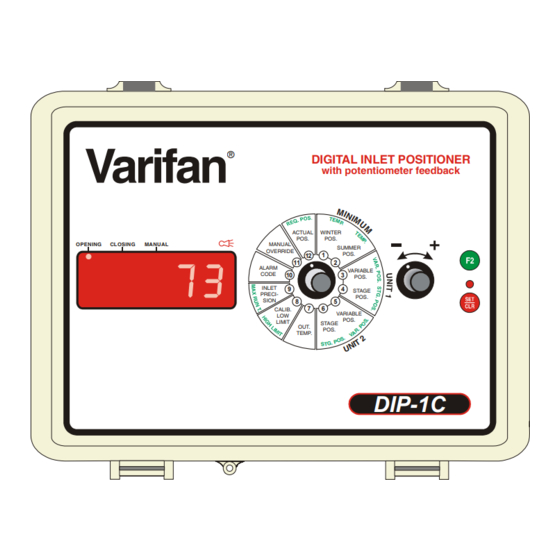
DIGITAL INLET POSITIONER
with potentiometer feedback
ACTUAL
WINTER
POS.
POS.
MANUAL
SUMMER
OVERRIDE
POS.
1
12
11
2
ALARM
VARIABLE
CODE
10
3
POS.
INLET
9
4
STAGE
PRECI-
POS.
SION
5
5
8
5
7
6
CALIB.
VARIABLE
LOW
POS.
LIMIT
STAGE
OUT.
POS.
TEMP.
www.monitrol.com
DIP-1C
Advertisement
Table of Contents

Related Manuals for Varifan DIP-1C


Summary of Contents for Varifan DIP-1C
- Page 1 MANUAL DIP-1C Varifan ® DIGITAL INLET POSITIONER with potentiometer feedback ACTUAL WINTER POS. POS. OPENING CLOSING MANUAL MANUAL SUMMER OVERRIDE POS. ALARM VARIABLE CODE POS. INLET STAGE PRECI- POS. SION CALIB. VARIABLE POS. LIMIT STAGE OUT. POS. TEMP. DIP-1C Installation / User’s Guide...
-
Page 2: Warnings And Precautions
DIP-1C WIRING DIAGRAM WARNINGS AND PRECAUTIONS Although the manufacturer has made every effort to ensure the accuracy of the information contained herein, this document is subject to change without notice due to ongoing product development. WARNINGS AND PRECAUTIONS Equipment, probe failure, blown fuses and/or tripped breakers may prove harmful to the contents of the building. - Page 3 DIP-1C WIRING DIAGRAM WIRING DIAGRAM DIP-1C SECTION A DIP-1C Section A-3 www.monitrol.com...
-
Page 4: Wiring Diagram (115/230Vac Inlet)
DIP-1C WIRING DIAGRAM Wiring Diagram (115/230VAC inlet) MGCB MGCB Section A-4 DIP-1C www.monitrol.com... -
Page 5: Wiring Diagram (24Vdc Inlet)
DIP-1C WIRING DIAGRAM Wiring Diagram (24VDC inlet) MGCB MGCB DIP-1C Section A-5 www.monitrol.com... -
Page 6: Electrician's Notes
DIP-1C WIRING DIAGRAM DIP-1C Electrician’s notes (COMMUNICATION WIRING) SHIELDED LOW CAPACITANCE WIRE, (Capacitance between conductors @ 1Khz = 24pF/ft), TWISTED PAIR (8 twist/ft), AWG #22, 820ft (250m) MAX LENGTH. (Ex.: BELDEN 8761) HIGH VOLTAGE WIRE INSTALLED ACCORDING TO LOCAL WIRING CODE. -
Page 7: Section B
DIP-1C INSTALLATION INSTALLATION DIP-1C SECTION B DIP-1C Section B-7 www.monitrol.com... -
Page 8: Unpacking
Failure to do so may void the warranty. Unpacking Unpack the DIP-1C and inspect contents for damage. Should the contents appear to be damaged, contact your local distributor to return the equipment. The package should contain the following standard items:... -
Page 9: General Installation Guidelines
DIP-1C INSTALLATION General installation guidelines DIP-1C Module It is recommended to install the unit in a hallway to limit the DIP-1C exposure to noxious gases. In order to avoid condensation problems inside the module, it is recommended to install the DIP-1C on an inside wall. If it is not possible, use spacers to have an air gap between the wall and the DIP-1C. -
Page 10: Electrical Power
DIP-1C INSTALLATION Electrical Power Protection from electrical surge should be included in the planning of each installation. It is strongly recommended to have a backup power source to ensure life- sustaining conditions in case of power failure (see figure 2). -
Page 11: Connection Procedure
DIP-1C INSTALLATION Connection Procedure Detailed Wiring Diagrams Typical Power Backup Wiring A backup relay (DPDT) connects to the power source 1 in normal operation but will switch to the power source 2 if source 1 is disabled. The backup relay should be selected to ensure it is able to support the required power load. -
Page 12: Typical Alarm Connection Wiring
DIP-1C INSTALLATION Typical Alarm Connection Wiring The DIP-1C provides a normally closed dry contact to set off an alarm (potentiometer problem, power loss or other malfunctions). It may be connected to an alarm system or directly to a siren and /or auto-dialer. -
Page 13: Powering Up Procedure
There are two ways to download a configuration in the DIP-1C. 1) Downloading by powering down. A. Ensure the power source of the DIP-1C is OFF (flip the circuit breaker on the distribution panel). B. Remove the faceplate screws and lift up the cover. -
Page 14: Uploading The Configuration
D. When the downloading procedure is complete, remove the configuration chip (MMX) and place it in the bottom part of the enclosure or in another safe location. Once the MMX Chip is removed, the DIP-1C starts up and executes the configuration. -
Page 15: Dip-1C Compatible Modules
DIP-1C INSTALLATION DIP-1C Compatible Modules This is the list of all compatible modules that can be connected with DIP-1C with a short description of their function. Computer interface NET-IN2 Communication Module (Module inserted into the DIP-1C to communicate with the computer interface) -
Page 16: Specifications
DIP-1C INSTALLATION Specifications Storage temperature -4°F to 131°F (-20°C to 55°C) Operating temperature 32°F to 113°F (0°C to 45°C) Humidity 90% maximum Non-condensing Weight 2,4 lb (1,1 kg) Size 9” x 7” x 4 3/4” (22.8 cm x 17.7 cm x 11.5 cm) -
Page 17: Troubleshooting
DIP-1C INSTALLATION Troubleshooting SYMPTOM CAUSE REMEDY Display is blank DIP-1C is not powered. Make sure the control is Flat cable between the powered. main and top boards of the Make sure the fuse is DIP-1C is disconnected. correct. Make sure the flat cable is connected. - Page 18 DIP-1C USER’S GUIDE USER’S GUIDE DIP-1C SECTION C Section C-18 DIP-1C www.monitrol.com...
-
Page 19: Module Description
DIP-1C USER’S GUIDE Module Description Varifan ® DIGITAL INLET POSITIONER with potentiometer feedback ACTUAL WINTER POS. POS. OPENING CLOSING MANUAL MANUAL SUMMER OVERRIDE POS. ALARM VARIABLE CODE POS. INLET STAGE PRECI- POS. SION CALIB. VARIABLE POS. LIMIT STAGE OUT. POS. - Page 20 DIP-1C USER’S GUIDE 1. Output LED Those LED indicate the status of an output. A LED comes ON whenever the respective output is active. 2. LED Status Windows The LED status window features a 5 digit LED readout display. After a setting is selected, its value appears on the LED display.
-
Page 21: Input/Output Table
DIP-1C USER’S GUIDE Input/Output Table Inputs Outputs Inlet Alarm Equipment Item Description DIP-1C Digital Inlet Positioner Configuration Versions Version Date Min. Proc Modification Version. 05/05/2011 New. 12/08/2014 Correction on the stage 8 visibility for the unit DIP-1C Section C-21 www.monitrol.com... -
Page 22: Ventilation System Overview
DIP-1C USER’S GUIDE Ventilation System Overview The DIP-1C is used to control an inlet according to the information received from one or two controllers. The inlet will open progressively according to the ventilation level. Some position can be influenced by the outside temperature. -
Page 23: Normal Mode Settings
Winter Minimum Position (POS 1) These parameters will only appear if the outside temperature is used on at least one of the units connected to the DIP-1C. Winter Minimum Position This parameter is used to adjust the minimum opening position when the Outside Temperature is equal to or below Winter Temp. -
Page 24: Unit 1 Variable Position (Pos 3)
DIP-1C USER’S GUIDE Unit 1 Variable Position (POS 3) Variable 1 Start Position 1-STR This parameter is used to establish the position the inlet will take when variable 1 of unit 1 runs at its minimum speed. When variable 1 of unit 1 runs above its minimum speed, the inlet’s opening will modulate from this... -
Page 25: Unit 1 Stage Position (Pos 4)
DIP-1C USER’S GUIDE Unit 1 Stage Position (POS 4) These stage positions will only appear if the corresponding stages are used as ventilation stages or as a mist stage with a 100% duty cycle. Stage 3 Position 3-POS This parameter is used to establish the position the inlet will take when stage 3 of unit 1 is activated. -
Page 26: Unit 2 Variable Position (Pos 5)
DIP-1C USER’S GUIDE Unit 2 Variable Position (POS 5) These positions will only appear if unit 2 is activated by setting DIPSW2 to ON (see DIP Switches and Slide Switches Table page 36). Variable 1 Start Position 1-STR This parameter is used to establish the position the inlet will take when variable 1 of unit 2 runs at its minimum speed. -
Page 27: Unit 2 Stage Position (Pos 6)
DIP-1C USER’S GUIDE Unit 2 Stage Position (POS 6) These stage positions will only appear if unit 2 is activated by setting DIPSW2 to ON (see DIP Switches and Slide Switches Table page 36) and the corresponding stages are used as ventilation stages or as a mist stage with a 100% duty cycle. -
Page 28: Inlet Calibration (Pos 8)
DIP-1C USER’S GUIDE Inlet Calibration (POS 8) Inlet Set Low Limit This parameter is used to set the low potentiometer limit for inlet calibration. This will effectively define the lowest possible value for the inlet’s potentiometer. To obtain this value, close the inlet completely using Manual Override. -
Page 29: Alarm Code (Pos 10)
DIP-1C USER’S GUIDE Alarm Code (POS 10) Alarm Code This setting displays the alarm condition. This parameter displays 0 when no errors have been detected. This indicates that the module has operated properly since it was powered up or since the Alarm Code was last cleared. -
Page 30: System Mode Settings
This parameter is used to set the position the inlet will take when no ventilation stages are activated and the Outside Temperature is not used. This parameter will appear only if none of the units connected to the DIP-1C use an outside temperature probe. This parameter is adjusted in 1% increments from 0% to 100%. -
Page 31: (Pos 10)
DIP-1C USER’S GUIDE (POS 10) RF Channel rF CH This parameter is used to select one of the 16 frequencies of the WiFarm network or deactivates wireless communication mode. If this parameter is OFF, other wireless communication parameters will disappear. -
Page 32: (Pos 12)
DIP-1C USER’S GUIDE (POS 12) System Parameters SYSTM This parameter indicates that the DIP-1C is in system parameter mode. Communication Filter FILTR This parameter is reserved for the manufacturer’s technical support personnel. Section C-32 DIP-1C www.monitrol.com... -
Page 33: Parameter Table
DIP-1C USER’S GUIDE Parameter Table Note: Some parameters will not be visible depending on certain settings. See Normal Mode Settings and System Mode Settings sections for more details User Settings DIP-1C (Accessible when SW2 is set to OFF) Parameters Default Range Actual Position —... - Page 34 DIP-1C USER’S GUIDE – Stage 3 Position 0 to 100% 3-POS 0 to 100% [F2] – 4-POS – Stage 4 Position (POS 6) [F2] – – Stage 5 Position 0 to 100% 5-PO5 UNIT 2 STAGE POSITION [F2] – – Stage 6 Position...
-
Page 35: System Settings Dip-1C (Accessible When Sw2 Is Set To On)
DIP-1C USER’S GUIDE System Settings DIP-1C (Accessible when SW2 is set to ON) Parameters Default Range (POS 1) — — — (POS 2) — — — (POS 3) — — — (POS 4) — — — (POS 5) — —... -
Page 36: Dip Switches And Slide Switches Table
DIP-1C USER’S GUIDE DIP Switches and Slide Switches Table Switches Default Settings (SW1) – Parameters Locked ON/OFF SLIDE SWITCHES (SW2) – System Parameters ON/OFF (DIPSW1) – Future Use — — (DIPSW2) – # Unit Connected OFF (1 Unit) OFF = 1 Unit / ON = 2 Units DIP SWITCHES (DIPSW3) –... - Page 37 DIP-1C INDEX / WARRANTY INDEX / WARRANTY DIP-1C SECTION D DIP-1C Section D-37 www.monitrol.com...
-
Page 38: Table Of Contents
Typical Alarm Connection Wiring ..................12 Powering Up Procedure ..................13 Verify all Connections ....................13 Hermetically Close the DIP-1C ................... 13 Put the power on ......................13 Secure the front panel with a lock ................13 Downloading the Configuration ................13 ... -
Page 39: Table Of Contents
(POS 12)........................32 Parameter Table ....................33 User Settings DIP-1C (Accessible when SW2 is set to OFF) ........33 System Settings DIP-1C (Accessible when SW2 is set to ON) ........35 DIP Switches and Slide Switches Table ............. 36 ... -
Page 40: Limited Warranty
DIP-1C INDEX / WARRANTY Limited Warranty The manufactured equipment and supplied components have gone through rigorous inspection to assure optimal quality of product and reliability. Individual controls are factory tested under load, however the possibility of equipment failure and/or malfunction may still exist. - Page 41 www.monitrol.com...
- Page 42 DIP-1C_EN VER: 1.1 August 12, 2014 www.monitrol.com...
Need help?
Do you have a question about the DIP-1C and is the answer not in the manual?
Questions and answers