Table of Contents
Advertisement
Quick Links
MANUAL
MST-5C
Varifan
1
2
3
4
5
73.3
Installation / User's Guide
ATTENTION ELECTRICIAN
SEE WIRING DETAILS ON PAGES A-3 TO A-5 AND
ADDITIONAL INFORMATION IN SECTION B
®
PRB
HI
off
REC
1
TIMER
12
11
2
LO
REC
10
3
9
4
11 12 1
10
10
9
9
5
5
8
8
8
5
7
6
DIFF
REL
DIFF
www.monitrol.com
5-STAGE
THERMOSTAT
on
REL
REL
REL
MST-5C
Advertisement
Table of Contents

Related Manuals for Varifan MST-5C


Summary of Contents for Varifan MST-5C
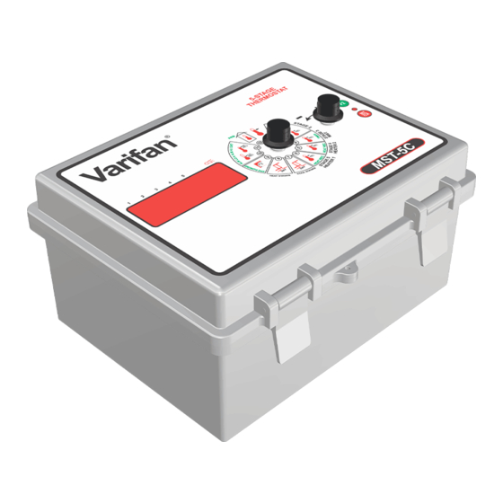
- Page 1 MANUAL MST-5C Varifan ® 5-STAGE THERMOSTAT TIMER 73.3 11 12 1 DIFF DIFF MST-5C Installation / User’s Guide ATTENTION ELECTRICIAN SEE WIRING DETAILS ON PAGES A-3 TO A-5 AND ADDITIONAL INFORMATION IN SECTION B www.monitrol.com...
-
Page 2: Warnings And Precautions
Furthermore the manufacturer recommends testing all the functions and equipment connected to the MST-5C, including the alarm system and backup devices, after installation, after changes to the installation and every month after that. - Page 3 MST-5C WIRING DIAGRAM WIRING DIAGRAM MST-5C SECTION A MST-5C Section A-3 www.monitrol.com...
-
Page 4: Wiring Diagram
MST-5C WIRING DIAGRAM Wiring Diagram GREEN RELATIVE HUMIDITY BLACK PROBE RH-3 MGCB WHITE RED CONNECTOR 8VAC INT 4 / EXT INSIDE 4 / OUTSIDE INT 3 INSIDE PROBE 3 INT 2 INSIDE PROBE INT 1 INSIDE PROBE Section A-4 MST-5C... -
Page 5: Electrician's Notes
MST-5C WIRING DIAGRAM MST-5C Electrician’s notes (PROBE WIRING) SHIELDED WIRE AWG #22 WITH 16/30 STRANDING, 500ft (150m) MAXIMUM LENGTH (Ex.: DECA 73-310). For other probe, refer to specific probe manual for appropriate maximum length and wire size or use AWG #22, 500ft (150m) MAXIMUM LENGTH. -
Page 6: Section B
MST-5C INSTALLATION INSTALLATION MST-5C SECTION B Section B-6 MST-5C www.monitrol.com... -
Page 7: Unpacking
The package should contain the following standard items: 1 MST-5C control (or MST-5C/H which includes a port for humidity probe) 4 Brackets / 4 screws 1 2004-10K temperature probe 1 Installation / User’s Guide... -
Page 8: General Installation Guidelines
MST-5C INSTALLATION General installation guidelines MST-5C Control It is recommended to install the unit in a hallway to limit the MST-5C exposure to noxious gases. In order to avoid condensation problems inside the controller, it is recommended to install the MST-5C on an inside wall. If it is not possible, use spacers to have an air gap between the wall and the MST-5C. -
Page 9: Electrical Power
(see figure 4). It is also strongly recommended to put a backup thermostat to sufficient fan and heating system parallel to the MST-5C module output (see figure 5). The backup system and alarm must be thoroughly tested and verified as working properly before using the ventilation system. -
Page 10: Connection Procedure
The inside temperature sensor should be located in the area which gives the most accurate temperature reading to achieve optimum ventilation. The sensor should also be connected to the MST-5C with a shielded two-wire cable. It should be located in an area protected from operating machinery, animal bites, personnel or anything that could damage the sensor. -
Page 11: Typical Power Backup Wiring
MST-5C INSTALLATION Typical Power Backup Wiring A backup relay (DPDT) connects to the power source 1 in normal operation but will switch to the power source 2 if source 1 is disabled. The backup relay should be selected to ensure it is able to support the required power load. -
Page 12: Typical Thermostat Backup Wiring
MST-5C INSTALLATION Typical Thermostat Backup Wiring If the MST-5C fails, the backup thermostats will activate the dedicated fan or heater as soon as temperature reaches the set point of the thermostat. The thermostat must be accessible for adjustment and must be set at 3 to 5 degrees above the fan’s relative set point or 3 to 5 degrees under the heater relative set... -
Page 13: Typical Alarm Connection Wiring
MST-5C INSTALLATION Typical Alarm Connection Wiring The MST-5C provides a normally closed dry contact to set off an alarm in case of a low or high temperature condition occurs. Moreover, this same contact can be used to signal a power failure or other malfunctions. It may be connected to an alarm system or directly to a siren and /or auto-dialer. -
Page 14: Powering Up Procedure
There are two ways to download a configuration in the MST-5C controller. 1) Downloading by powering down. A. Ensure the power source of the MST-5C is OFF (flip the circuit breaker on the distribution panel). B. Remove the faceplate screws and lift up the cover. -
Page 15: Uploading The Configuration
D. When the downloading procedure is complete, remove the configuration chip (MMX) and place it in the bottom part of the enclosure or in another safe location. Once the MMX Chip is removed, the MST-5C starts up and executes the configuration. -
Page 16: Mst-5C Compatible Probes
MST-5C INSTALLATION MST-5C Compatible Probes This is the list of all compatible probes that can be connected with MST-5C control with a short description of their function. Temperature probe 2004-10K (black cap) Temperature probe with a temperature range of -58 to 140°F (-50 to 60°C). -
Page 17: Specifications
MST-5C INSTALLATION Specifications Storage temperature -4°F to 131°F (-20°C to 55°C) Operating temperature 32°F to 113°F (0°C to 45°C) Humidity 90% maximum Non-condensing Weight 2,4 lb (1,1 kg) Size 9” x 7” x 4 3/4” (22.8 cm x 17.7 cm x 11.5 cm) -
Page 18: Troubleshooting
Probe is short circuited or the temperature is within defective. normal range, replace the probe. Displays are blank MST-5C is not powered. Make sure the control is Flat cable between the powered. main and top boards of the Make sure the flat cable is MST-5C is disconnected. - Page 19 MST-5C USER’S GUIDE USER’S GUIDE MST-5C SECTION C MST-5C Section C-19 www.monitrol.com...
-
Page 20: Control Description
MST-5C USER’S GUIDE Control Description Varifan ® 5-STAGE THERMOSTAT TIMER 73.3 11 12 1 DIFF DIFF MST-5C Section C-20 MST-5C www.monitrol.com... - Page 21 MST-5C USER’S GUIDE 1. Output LED Those LED indicate the status of an output. A LED comes ON whenever the respective output is active. 2. LED Status Windows The LED status window features a 5 digit LED readout display of temperature in Fahrenheit or Celsius, or other programmable settings.
-
Page 22: Input/Output Table
MST-5C USER’S GUIDE Input/Output Table Inputs Outputs Inside Temperature 1 to 4 ON/OFF Stage 2 to 5 Outside Temperature Up to 1 Mist Up to 1 Relative Humidity Up to 1 Heater Up to 2 Alarm Equipment Item Description MST-5C... -
Page 23: Ventilation System Overview
MST-5C USER’S GUIDE Ventilation system overview The MST-5C uses up to 4 inside temperature probes, an outside temperature probe and a relative humidity probe to control 5 on/off stages. Stage 1 can operate according to a timer when temperature is under its activation set point. -
Page 24: Normal Mode Settings
MST-5C USER’S GUIDE Normal Mode Settings Set Point (POS 1) Main Set Point This is the temperature goal for the room, the activation temperature for stage 1 and the reference temperature for all relative settings. The Main Set Point will follow its growth curve when the Growth Day is not ON. -
Page 25: Stage 3 / Mist (Pos 4)
MST-5C USER’S GUIDE Stage 3 / Mist (POS 4) Relative Temperature Stage 3 / Mist This parameter is used to establish the relative temperature at which stage 3 / mist will activate. When the Average Temperature reaches Main Set Point + Relative Temperature Stage 3 / Mist, stage 3 / mist will activate according to its cycle. -
Page 26: Stage 5 / Heater 1 (Pos 6)
This para meter disp plays the tim me for wh ich heater 2 has bee en activate since the MST-5C was powe ered up or r since this s paramete er was las cleared. T To reset this s value to 0... -
Page 27: Heater Stages (Pos 8)
DAy rowth Day This param meter is us se to adjust t the growth h day of the e MST-5C controller. this day is s not set to OFF, it will deter rmine the v value of th... -
Page 28: High Temperature Record And Alarm (Pos 11)
High Average Temperature Record This parameter displays the highest value reached by the Average Temperature since the MST-5C was powered up or since this parameter was last cleared. To reset this value to the actual Average Temperature, press the SET/CLR button. The High Average Temperature Record is displayed to the nearest 0.1°... -
Page 29: Average / Probes (Pos 12)
MST-5C USER’S GUIDE High Alarm Relative Temperature AL HI This parameter is used to establish the relative temperature at which a high temperature alarm condition will occur. When Average Temperature is above the Main Set Point + High Alarm Relative Temperature, a high temperature alarm condition will occur. -
Page 30: System Mode Settings
MST-5C USER’S GUIDE Probe 4 P :4 This parameter displays the actual probe 4 temperature. This parameter will appear only if DIPSW4 is set to the ON position and DIPSW5 is set to the OFF position (see DIP Switches and Slide Switches Table page 38). The Probe 4 temperature is displayed to the nearest 0.1°... -
Page 31: (Pos 6)
MST-5C USER’S GUIDE Probe 1 Heater 2 p1:Ht2 This parameter is used to assign Probe 1 to the temperature heater 2 will ON, Probe 1 will be averaged with the follow. If this parameter is set to other selected probes to compose the temperature heater 2 will follow. If... - Page 32 MST-5C USER’S GUIDE Probe 1 Heater 1 p1:Ht1 This parameter is used to assign Probe 1 to the temperature heater 1 will ON, Probe 1 will be averaged with the follow. If this parameter is set to other selected probes to compose the temperature heater 1 will follow. If...
-
Page 33: (Pos 8)
A-P, the Clock parameter will be displayed in the AM/PM format. Display Language LANG This parameter is used to select the language used by the MST-5C. If this ENG, the configuration will use the English language. parameter is set to... -
Page 34: (Pos 11)
This parameter displays the version of the configuration actually used. Processor Version Proc This parameter displays the version of the processor actually used. (POS 12) System Parameters SYSTM This parameter indicates that the MST-5C is in system parameter mode. Section C-34 MST-5C www.monitrol.com... -
Page 35: Parameter Table
MST- 5C USER R’S GUIDE rameter Table rmal Mod e Setting gs (Acces ssible wh hen SW2 i is set to O OFF) Parameter Default ange -58.0 to o 140.0°F Average Te emperature — (-50.0 to o 60.0°C) (POS 12) [F2] –... - Page 36 AL HI 12.0 0°F (6.7°C) 0.5 to 40.0°F (0.3 to 22.2°C ALARM Relative Tem mperature 100.0°F -40.0 to 11 19.9°F, OFF [F2] – CRiT – Critical High h Alarm (37.8°C) (-40.0 to 48 8.8°C, OFF) Sect ion C-36 MST-5C www.monitrol.com...
-
Page 37: System Mode Settings (Accessible When Sw2 Is Set To On)
MST-5C USER’S GUIDE System Mode Settings (Accessible when SW2 is set to ON) Parameters Default Range (POS 1) – MSP Curve ON/OFF CSETP: (POS 2) — — — (POS 3) — — — (POS 4) — — — – Logic Out 4... -
Page 38: Dip Switches And Slide Switches Table
MST-5C USER’S GUIDE DIP Switches and Slide Switches Table Switches Default Settings (SW1) – Parameters Lock OFF (Unlock) ON = Lock / OFF = Unlock SLIDE SWITCHES (SW2) – System Mode Parameters OFF (Normal) ON = System / OFF = Normal (DIPSW1) –... -
Page 39: Motor Curve Table
MST-5C USER’S GUIDE Motor Curve Table TYPE OF MOTOR CURVE BRAND MODEL VOLTAGE HEIGHT Multifan 4E40 230 V. 16” Flex FM0025 230 V. 18” Multifan 2E20 230 V. 8” Multifan 4E35 230 V. 14” Multifan 4E50 230 V. 20” Multifan AF24M’E... -
Page 40: Additional Information On Parameters
The following is a more detailed description of general-purpose parameters. Time of Day (time clock) The MST-5C comes with its own integrated time clock. This feature is appreciated by users who want to know the current time of day. Note that if a power failure occurs, the clock will not run and will start back at the time the power failure occurred. - Page 41 MST-5C USER’S GUIDE When a day is displayed, pressing the F2 button will display the associated value. When a value is displayed, pressing the F2 button will display the next day. The following graph shows a typical ramping curve for the temperature.
- Page 42 MST-5C USER’S GUIDE 11. The whole ramping curve is now set. To enable temperature ramping, simply set the Growth Day to any day value and the MST-5C will follow the curve. Ramping is interrupted when days fail to respect a chronological order or when two consecutive points have the same day.
-
Page 43: Section D
MST-5C INDEX / WARRANTY INDEX / WARRANTY MST-5C SECTION D MST-5C Section D-43 www.monitrol.com... -
Page 44: Table Of Contents
Typical Alarm Connection Wiring ..................13 Powering Up Procedure ..................14 Verify all Connections ....................14 Hermetically Close the MST-5C ................. 14 Put the power on ......................14 Secure the front panel with a lock ................14 Downloading the Configuration ................14 ... -
Page 45: Table Of Contents
MST-5C INDEX / WARRANTY TABLE OF CONTENTS Section C Control Description ..................... 20 Input/Output Table ...................... 22 Equipment ........................22 Configuration Versions ....................22 Ventilation system overview ..................23 Normal Mode Settings ..................24 Set Point (POS 1) ....................... 24 ... -
Page 46: Limited Warranty
MST-5C INDEX / WARRANTY Limited Warranty The manufactured equipment and supplied components have gone through rigorous inspection to assure optimal quality of product and reliability. Individual controls are factory tested under load, however the possibility of equipment failure and/or malfunction may still exist. - Page 47 www.monitrol.com...
- Page 48 MST-5C_EN VER:1.3 November 20, 2012 www.monitrol.com...
Need help?
Do you have a question about the MST-5C and is the answer not in the manual?
Questions and answers