Table of Contents
Advertisement
Quick Links
MANUAL
CPS-2C
Varifan
1
2
OPEN CLOSE
MAN
OPEN
CLOSE
MAN
73.3
Installation / User's Guide
ATTENTION ELECTRICIAN
SEE WIRE DETAILS ON PAGES A-3 TO A-6 AND
ADDITIONAL INFORMATION IN SECTION B
®
2 AIR INLETS / CURTAINS
temperature / static pressure
1
PRB
PRB
12
1
11
2
on
off
10
3
OPEN
OPEN
9
4
on
off
5
5
8
5
CLOSE
CLOSE
7
6
HI
HI
REC
REC
LO
LO
REC
REC
2
on
off
on
off
CPS-2C
Advertisement
Table of Contents

Subscribe to Our Youtube Channel
Related Manuals for Varifan CPS-2C


Summary of Contents for Varifan CPS-2C
- Page 1 MANUAL CPS-2C Varifan ® 2 AIR INLETS / CURTAINS temperature / static pressure OPEN CLOSE OPEN CLOSE 73.3 OPEN OPEN CLOSE CLOSE CPS-2C Installation / User’s Guide ATTENTION ELECTRICIAN SEE WIRE DETAILS ON PAGES A-3 TO A-6 AND ADDITIONAL INFORMATION IN SECTION B...
-
Page 2: Warnings And Precautions
Furthermore the manufacturer recommends testing all the functions and equipment connected to the CPS-2C, including the alarm system and backup devices, after installation, after changes to the installation and every month after that. - Page 3 CPS-2C WIRING DIAGRAM WIRING DIAGRAM CPS-2C SECTION A CPS-2C Section A-3...
-
Page 4: Wiring Diagram Temperature Mode
CPS-2C WIRING DIAGRAM Wiring Diagram Temperature Mode 8VAC INT 2 INSIDE PROBE INT 1 INSIDE PROBE Section A-4 CPS-2C... -
Page 5: Wiring Diagram Static Pressure Mode
CPS-2C WIRING DIAGRAM Wiring Diagram Static Pressure Mode 8VAC INT 2 STATIC PRESSURE INT 1 GE-SP1 (4-20mA) STATIC PRESSURE GE-SP1 (4-20mA) CPS-2C Section A-5... -
Page 6: Electrician's Notes
CPS-2C WIRING DIAGRAM CPS-2C Electrician’s notes (PROBE WIRING) SHIELDED WIRE AWG #22 WITH 16/30 STRANDING, 500ft (150m) MAXIMUM LENGTH (Ex.: DECA 73-310). For other probe, refer to specific probe manual for appropriate maximum length and wire size or use AWG #22, 500ft (150m) MAXIMUM LENGTH. -
Page 7: Section B
CPS-2C INSTALLATION INSTALLATION CPS-2C SECTION B CPS-2C Section B-7... -
Page 8: Unpacking
Failure to do so may void the warranty. Unpacking Unpack the CPS-2C and inspect contents for damage. Should the contents appear to be damaged, contact your local distributor to return the equipment. The package should contain the following standard items:... -
Page 9: General Installation Guidelines
CPS-2C INSTALLATION General installation guidelines CPS-2C Control It is recommended to install the unit in a hallway to limit the CPS-2C exposure to noxious gases. In order to avoid condensation problems inside the controller, it is recommended to install the CPS-2C on an inside wall. If it is not possible, use spacers to have an air gap between the wall and the CPS-2C. -
Page 10: Electrical Power
CPS-2C INSTALLATION Electrical Power Protection from electrical surge should be included in the planning of each installation. It is strongly recommended to have a backup power source to ensure life- sustaining conditions in case of power failure (see figure 4). -
Page 11: Connection Procedure
The inside temperature sensor should be located in the area which gives the most accurate temperature reading to achieve optimum ventilation. The sensor should also be connected to the CPS-2C with a shielded two-wire cable. It should be located in an area protected from operating machinery, animal bites, personnel or anything that could damage the sensor. -
Page 12: Typical Power Backup Wiring
CPS-2C INSTALLATION Typical Power Backup Wiring A backup relay (DPDT) connects to the power source 1 in normal operation but will switch to the power source 2 if source 1 is disabled. The backup relay should be selected to ensure it is able to support the required power load. -
Page 13: Typical Alarm Connection Wiring
CPS-2C INSTALLATION Typical Alarm Connection Wiring The CPS-2C provides a normally closed dry contact to set off an alarm in case low or high temperature condition occurs. Moreover, this same contact can be used to signal a power failure or other malfunctions. It may be connected to an alarm system or directly to a siren and /or auto-dialer. -
Page 14: Powering Up Procedure
CPS-2C INSTALLATION Powering Up Procedure Once the CPS-2C is properly mounted on the wall and all modules and sensors connected to the terminal block, perform the following step: Verify all Connections Seal all cable entry holes. Hermetically Close the CPS-2C Close the front panel and the lower access cover. -
Page 15: Downloading The Configuration
There are two ways to download a configuration in the CPS-2C controller. 1) Downloading by powering down. A. Ensure the power source of the CPS-2C is OFF (flip the circuit breaker on the distribution panel). B. Remove the faceplate screws and lift up the cover. -
Page 16: Uploading The Configuration
E. When the uploading procedure is complete, remove the configuration chip (MMX) and place it in the bottom part of the enclosure or in another safe location. Once the MMX Chip is removed, the CPS-2C will continue to execute the configuration. -
Page 17: Cps-2C Compatible Probes
CPS-2C INSTALLATION CPS-2C Compatible Probes This is the list of all compatible probes that can be connected with CPS-2C control with a short description of their function. Temperature probe 2004-10K (black cap) Temperature probe with a temperature range of -58 to 140°F (-50 to 60°C). -
Page 18: Specifications
CPS-2C INSTALLATION Specifications Storage temperature -4°F to 131°F (-20°C to 55°C) Operating temperature 32°F to 113°F (0°C to 45°C) Humidity 90% maximum Non-condensing Weight 2.4 lb (1.1 kg) Size 8 1/2” x 7” x 4 3/4” (22.6 cm x 17.7 cm x 11.5... -
Page 19: Troubleshooting
Probe is short circuited or the temperature is within defective. normal range, replace the probe. Displays are blank CPS-2C is not powered. Make sure the control is Flat cable between the powered. main and top boards of the Make sure the fuse is CPS-2C is disconnected. - Page 20 CPS-2C USER’S GUIDE USER’S GUIDE CPS-2C SECTION C Section C-20 CPS-2C...
-
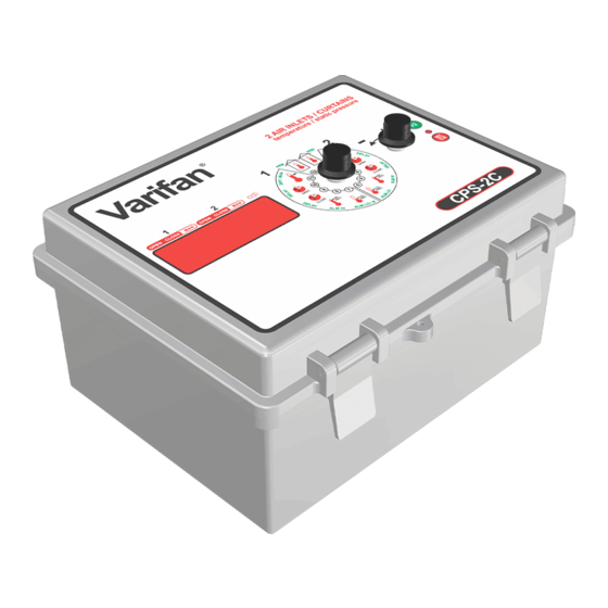
Page 21: Control Description
CPS-2C USER’S GUIDE Control Description Varifan ® 2 AIR INLETS / CURTAINS temperature / static pressure OPEN CLOSE OPEN CLOSE 73.3 OPEN OPEN CLOSE CLOSE CPS-2C CPS-2C Section C-21... - Page 22 CPS-2C USER’S GUIDE 1. Output LED Those LED indicate the status of an output. A LED comes ON whenever the respective output is active. You can also check if a inlet/curtain is in manual mode. 2. LED Status Windows The LED status window features a 5 digit LED readout display of temperature in Fahrenheit or Celsius, or other programmable settings.
-
Page 23: Input/Output Table
CPS-2C USER’S GUIDE Input/Output Table Inputs Outputs Inside Temperature 0 or 2 Inlets Static Pressure 0 or 2 Alarm Equipment Item Description CPS-2C 2 Air Inlets/Curtains 2004-10k Temperature Sensor - Black 0 or 2 (-58°F to 140°F) (-50°C to 60°C) GE-SP1 Static Pressure Sensor –... -
Page 24: Ventilation System Overview
CPS-2C USER’S GUIDE Ventilation system overview The CPS-2C uses 2 probes, which can be set to temperature mode, static pressure mode or sensitive static pressure mode. The 2 probes are use to operate 1 inlet each. When a temperature probe is defective (short-circuited or unplugged), the CPS- 2C controller the alarm will sound. -
Page 25: Normal Mode Settings
CPS-2C USER’S GUIDE Normal Mode Settings Probe 2 (POS 1) Probe 2 Readout This parameter displays the actual probe 2 temperature/static pressure. ERR if probe 2 is defective or unplugged. This parameter may display Probe 2 Readout is displayed to the nearest 0.1° from -58.0°F to 140.0°F (-50.0°C to 60.0°C) or from -0.500’’H... -
Page 26: Open Time 2 (Pos 3)
Probe 2 Maximum This parameter displays the highest value reached by Probe 2 since the CPS-2C was powered up or since this parameter was last cleared. To reset this value to the actual Probe 2 Readout, press the SET/CLR button. The Probe 2 Maximum is displayed to the nearest 0.1°... -
Page 27: Probe 2 Min (Pos 6)
Probe 2 Minimum This parameter displays the lowest value reached by Probe 2 since the CPS-2C was powered up or since this parameter was last cleared. To reset this value to the actual Probe 2 Readout, press the SET/CLR button. The Probe 2 Minimum is displayed to the nearest 0.1°... -
Page 28: Probe 1 Max (Pos 8)
Probe 1 Maximum This parameter displays the highest value reached by Probe 1 since the CPS-2C was powered up or since this parameter was last cleared. To reset this value to the actual Probe 1 Readout, press the SET/CLR button. The Probe 1 Maximum is displayed to the nearest 0.1°... -
Page 29: Open Time 1 (Pos 10)
CPS-2C USER’S GUIDE Open Time 1 (POS 10) TIMER Open Time 1 This parameter is used to establish the duration of the run time for inlet 1 when it receives an opening demand. When Probe 1 Readout is above Main Set Point 1, inlet 1 will wait for Open Delay 1 before opening for Open Time 1. -
Page 30: Probe 1 (Pos 12)
CPS-2C USER’S GUIDE Probe 1 (POS 12) Probe 1 Readout This parameter displays the actual probe 1 temperature/static pressure. ERR if probe 1 is defective or unplugged. This parameter may display Probe 1 Readout is displayed to the nearest 0.1° from -58.0°F to 140.0°F (-50.0°C to 60.0°C) or from -0.500’’H... -
Page 31: System Mode Settings
OFF, day -10 to day 365. (POS 9) Display Language LANG This parameter is used to select the language used by the CPS-2C. Is this ENG, the configuration will use the English language. parameter is set to Is this parameter is set to FrA, the configuration will use the French language. -
Page 32: (Pos 11)
This parameter displays the version of the configuration actually used. Processor Version Proc This parameter displays the version of the processor actually used. (POS 12) System Parameters SYSTM This parameter indicates that the CPS-2C is in system parameter mode. Section C-32 CPS-2C... -
Page 33: Parameter Table
CPS-2C USER’S GUIDE Parameter Table Normal Mode Settings (Accessible when SW2 is set to OFF) Parameters Default Range (POS 1) -58.0 to 140.0°F PROBE 2 (-50.0 to 60.0°C) Probe 2 Readout — -0.500’’H O to 0.500’’H -40.0 to 100.0°F 67.0°F (19.4°C) (-40.0 to 37.8°C) - Page 34 CPS-2C USER’S GUIDE -58.0 to 140.0°F (-50.0 to 60.0°C) Probe 1 Minimum — (POS 7) PROBE 1 MIN -0.500’’H O to 0.500’’H -10.0°F (-5.6°C) -40.0 to -0.5°F (-22.2 to -0.3°C) [F2] – – Low Alarm 1 Lo AL -0.100’’H -0.500’’H O to 0.000’’H...
-
Page 35: System Mode Settings (Accessible When Sw2 Is Set To On)
CPS-2C USER’S GUIDE System Mode Settings (Accessible when SW2 is set to ON) Parameters Default Range – Clock — — Hovr (POS 1) 24hr [F2] – – Clock Format AM-PM, 24hr (POS 2) – Growth Day OFF, -10 to 365... -
Page 36: Dip Switches And Slide Switches Table
CPS-2C USER’S GUIDE DIP Switches and Slide Switches Table Switches Default Settings (SW1) – Parameters Protected ON/OFF SLIDE SWITCHES (SW2) – System Parameters ON/OFF (DIPSW1) – Temperature Unit ON (˚C) ON= ˚C / OFF = ˚F ON = Normal (DIPSW2) – Static Pressure Mode... -
Page 37: Additional Information On Parameters
The following is a more detailed description of general-purpose parameters. Time of Day (time clock) The CPS-2C comes with its own integrated time clock. This feature is appreciated by users who want to know the current time of day. Note that if a power failure occurs, the clock will not run and will start back at the time the power failure occurred. - Page 38 CPS-2C INDEX / WARRANTY INDEX / WARRANTY CPS-2C SECTION D...
-
Page 39: Table Of Contents
Typical Alarm Connection Wiring ...................13 Powering Up Procedure ..................14 Verify all Connections ....................14 Hermetically Close the CPS-2C .................. 14 Put the power on ......................14 Secure the front panel with a lock ................14 Downloading the Configuration ................15 ... -
Page 40: Table Of Contents
CPS-2C INDEX / WARRANTY TABLE OF CONTENTS Section C Control Description ..................... 21 Input/Output Table ...................... 23 Equipment ........................23 Configuration Versions ....................23 Ventilation system overview ..................24 Normal Mode Settings ..................25 Probe 2 (POS 1) ......................25 ... -
Page 41: Limited Warranty
CPS-2C INDEX / WARRANTY Limited Warranty The manufactured equipment and supplied components have gone through rigorous inspection to assure optimal quality of product and reliability. Individual controls are factory tested under load, however the possibility of equipment failure and/or malfunction may still exist. - Page 42 CPS-2C VER:1.2 November 21, 2011...
Need help?
Do you have a question about the CPS-2C and is the answer not in the manual?
Questions and answers