
Related Manuals for Varifan MST-2B


Summary of Contents for Varifan MST-2B
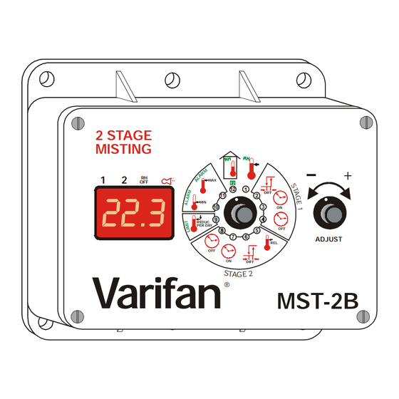
- Page 1 MST-2B INSTALLATION GUIDE / USER’S GUIDE 2 STAGE MISTING DIFF 2 2 . 3 REDUC. PER DAY ADJUST DIFF Varifan ® MST-2B...
- Page 2 Further more the manufacturer recommends to test all the functions and equipment connected to the MST-2B, including the alarm system and backup devices, after installation, after change to the installation and at least once a month after that.
-
Page 3: Table Of Contents
TABLE OF CONTENTS CHAPTER 1 - INTRODUCTION General ................5 Description ...............5 Definition of terms .................7 CHAPTER 2 - INSTALLATION Unpacking ................9 Installation ...............10 Switch settings ..............10 2.3.1 Line voltage selector switch ..........10 2.3.2 Software setting switches ..........11 Connection procedure .............11 2.4.1 Input power ..............11 2.4.1.1 115 VAC ................11... - Page 4 MST-2B TABLE OF CONTENTS CONTINUED... SECONDARY FUNCTIONS Relative humidity set point ............30 Minimum Ramping ...............31 Low Temperature Alarm ...............32 High Temperature Alarm ..............33 Relative humidity display ..............34 APPENDIX Troubleshooting ................35 Technical specifications ...............36 Record form .................37 Page 4...
-
Page 5: Chapter 1 - Introduction
CHAPTER 1 - INTRODUCTION CHAPITRE 1 - INTRODUCTION 1. GENERAL This manual provides the information necessary for the installation and operation of an MST-2B unit. The information is presented as follows: • Introduction • Installation • User’s Guide • Troubleshooting 1.1 DESCRIPTION... - Page 6 MST-2B DESCRIPTION CONTINUED... The MST-2B keeps you informed of the output status as well as the actual ambient temperature by displaying them constantly. An alarm will warn you if the ambient temperature is not within the pre-established limits. The output is protected by a fuse and all programmed parameters are preserved, even when the MST-2B is not powered.
-
Page 7: Definition Of Terms
CHAPTER 1 - INTRODUCTION DEFINITION OF TERMS MAIN SET POINT The desired room temperature. All other temperature parameters adjusted in the MST-2B are relative to this reference temperature. AMBIENT TEMPERATURE The ambient room temperature. RAMPING Automatic daily reduction of the main set point. - Page 8 MST-2B Page 8...
-
Page 9: Chapter 2 - Installation
Failure to comply may void the warranty! 2.1 UNPACKING Unpack the MST-2B and inspect contents for damage. Should the contents be damaged, contact your local distributor to return the material. The package should contain the following standard items: •... -
Page 10: Switch Settings
Mounting hardware is not included with the unit. Install the MST-2B using the mounting holes drilled in the side of the casing. Once the MST-2B is in place, use a screwdriver to remove the faceplate. 2.3 SWITCH SETTINGS 2.3.1 - LINE VOLTAGE SELECTOR SWITCH... -
Page 11: Software Setting Switches
CHAPTER 2 - INSTALLATION Certain parameters of the MST-2B are configured by the following switches: 2.3.2 Software setting switches These switches are located at the rear of the MST-2B faceplate and are used to adjust the following options: Fahrenheit Celsius... -
Page 12: 230 Vac
MST-2B 2.4.1.2 - 230VCA Make sure the line voltage selector switch is set to 230VAC. Connect the power cable to terminals 3 and 4 on the main (bottom) board. 2.4.2 - Mist output (terminals 5 and 6) The relay can drive a load of 10 Amp maximum. -
Page 13: Alarm
Make the normally open or normally closed connections as shown in figure 2. Momentary power interruptions may trigger false alarms! To avoid false alarming when the MST-2B is connected to an alarm system, install a time delay relay between the MST-2B and the alarm system. - Page 14 MST-2B Fig. 1 Wiring diagram for the mister output. Note for figure 1. Power cut and protection devices in case of an overload.. Optional humidity probe RH-3 WHITE BLACK blue connector Fig. 2 Probe and alarm connection. Page 14...
- Page 15 CHAPTER 2 - INSTALLATION Terminal Block Shield It is recommended to solder the probes’ junctions Fig. 3 Probe connection for temperature averaging. Fig. 4 Main (bottom) Board: Terminal blocks, switches and fuse location. Page 15...
-
Page 16: Chapter 3 - User's Guide
PER DAY ADJUST DIFF CHAPTER 3 - USER’S GUIDE The MST-2B front panel shown above features a LED status window and two control dials which are respectively used to select a function and adjust a setting. LED STATUS WINDOW The LED status window features a 3 digit LED display for temperature in Fahrenheit or Celsius, and programmable settings. - Page 17 Any one of these functions is selected by rotating the selector dial to the corresponding number and associated graphical image printed on the faceplate of the MST-2B. When primary functions 1 through 11 are selected, the LED status window displays a blinking value. Function 12 displays room temperature.
-
Page 18: Primary Fonctions
Adjuster dial counter clockwise to decrease the temperature setting, and clockwise to increase it. The main set point temperature is displayed on the MST-2B. Note: The ramping feature (primary function 9) must be (OFF) to adjust the main set point. -
Page 19: Stage 1 Differential
10°F (5.0°C). Adjusting stage 1 differential: • rotate the Selector dial to position (2), • rotate the Adjuster dial counter clockwise to decrease the differential, and clockwise to increase it. The stage 1 differential is displayed on the MST-2B. Page 19... -
Page 20: Stage 1 Timer Run Time
MST-2B STAGE 1 TIMER RUN TIME Stage timer activated when ambient temperature reaches the main set point. When the mist output is activated using this timer, the LED directly beneath the number “1” will be continuously illuminated. The stage 1 timer run time is adjusted in 1-minute increments from a minimum setting of 1 minute to a maximum setting of 60 minutes. -
Page 21: Stage 1 Timer Idle Time
Adjusting stage 1 timer idle time: • rotate the Selector dial to position (4), • rotate the Adjuster dial counter clockwise to decrease the idle time, and clockwise to increase it. The stage 1 timer idle time is displayed on the MST-2B. Page 21... -
Page 22: Stage 2 Relative Set Point
(0.0°C) to a maximum setting of 18.0°F (10.0°C). Adjusting the stage 2 RSP: • rotate the Selector dial to position (5), • rotate the Adjuster dial counter clockwise to decrease relative point, clockwise to increase it. The stage 2 RSP is displayed on the MST-2B. Page 22... -
Page 23: Stage 2 Differential
(0.5°C) to a maximum setting of 10°F (5.0°C). Adjusting stage 2 differential: • rotate the Selector dial to position (6), • rotate the Adjuster dial counter clockwise to decrease the differential, and clockwise to increase it. The stage 2 differential is displayed on the MST-2B. Page 23... -
Page 24: Stage 2 Timer Run Time
MST-2B STAGE 2 TIMER RUN TIME Stage 2 timer is activated when ambient temperature reaches the stage 2 RSP. When the mist output is activated using this timer, the LED directly beneath the number “2” will be continuously illuminated. The stage 2 timer run time is adjusted in 1-minute increments from a minimum setting of 1 minute to a maximum setting of 60 minutes. -
Page 25: Stage 2 Timer Idle Time
Adjusting stage 2 timer idle time: • rotate the Selector dial to position (8), • rotate the Adjuster dial counter clockwise to decrease the idle time, and clockwise to increase it. The stage 2 timer idle time is displayed on the MST-2B. Page 25... -
Page 26: Ramping
• rotate the adjuster dial counter clockwise to increase the ramping rate, and clockwise to decrease it. The ramping setting is displayed on the MST-2B. NOTE: When ramping is activated, the main set point temperature cannot be manually adjusted. Ramping automatically shuts OFF when the... -
Page 27: Low Temperature Record
13.5°F is recorded, Lo is displayed. Viewing the lowest temperature recorded: • rotate the selector dial to position (10) Clearing the low temperature value • quickly rotate the adjuster dial counter clockwise, then clockwise. CLr will be briefly displayed on the MST-2B. Page 27... -
Page 28: High Temperature Record
105.0°F (41.0°C) is recorded, Hi is displayed. Displaying highest temperature recorded: • rotate the selector dial to position (11) Clearing the high temperature value • quickly rotate the adjuster dial counter clockwise, then clockwise. CLr will be briefly displayed on the MST-2B. Page 28... -
Page 29: Ambient Room Temperature Display
(41.0°C). If the temperature is lower than 13.5°F (-10.0°C), Lo is displayed. If the temperature is higher than 105.0°F (41.0°C), Hi is displayed. Viewing the room temperature: • rotate the selector dial to position (12) Room temperature is displayed on the MST-2B. Page 29... -
Page 30: Secondary Functions
MST-2B SECONDARY FUNCTIONS HUMIDITY SET POINT The MST-2B may be equipped with an optional humidity probe. This setting prevents the mist from activating or deactivates it if humidity is high. The mist output will remain inactive until relative humidity decreases below this set point. -
Page 31: Minimum Ramping
Adjuster dial counterclockwise to decrease the minimum ramping setting, clockwise to increase it. The minimum ramping setting is displayed on the MST-2B. NOTE: When the main set point temperature reaches the minimum ramping limit, the ramping setting (primary function 9) automatically shuts off. -
Page 32: Low Temperature Alarm
When a low temperature alarm occurs an alarm contact is activated and the alarm LED lights on the MST-2B. Alarm The low temperature alarm is adjusted in 0.5 degree increments from a minimum setting of -32.0°F (-18.0°C) to a maximum setting of... -
Page 33: High Temperature Alarm
When a high temperature alarm occurs, an alarm contact is activated and the alarm LED lights up on the MST-2B. Alarm The high temperature alarm is adjusted in 0.5 degree increments from a minimum setting of 0.0°F (0.0°C) to a maximum setting of 32.0°F... -
Page 34: Relative Humidity Display
F2 will be displayed. Displaying the relative humidity: • rotate the selector dial to position (12), • rapidly rotate the adjuster dial back and forth to enter secondary function mode. The relative humidity is displayed on the MST-2B. Page 34... -
Page 35: Appendix
APPENDIX TROUBLESHOOTING SYMPTOM CAUSE and SOLUTION − Lo is continually ° Temperature is below minimum (13.5 displayed ° or -10.0 − Probe is disconnected or defective. − Hi is continually Temperature above maximum displayed (105.0°F or 41°C). − Probe is short circuited. −... -
Page 36: Technical Specifications
MST-2B TECHNICAL SPECIFICATIONS DESCRIPTION VALEUR − INPUT POWER 100 mA − 115/230 VAC − 60 Hz only − Output 1 10 Amp. 115 / 230 VAC (relay) − 1/2 HP @ 115V − 1 HP@ 230V − Minimum load 10 mA @ 115 VCA* −... -
Page 37: Record Form
APPENDIX RECORD FORM Pos Function Default value User setting Main set point 77°F 25°C Stage 1 differential 5.5°F 2°C Stage 1 timer run time Stage 1 timer idle time Stage 2 relative set point 3.5°F 2.0°C Stage 2 differential 5.5°F 3.0°C Stage 2 timer run time Stage 2 timer idle time... - Page 38 MST-2B Page 38...
- Page 39 WARRANTY Limited Warranty The manufactured equipment and supplied components have gone through rigorous inspection to assure optimal quality of product and reliability. Individual controls are factory tested under load, however the possibility of equipment failure and/or malfunction may still exist. For service, contact your local retailer or supplier.
- Page 40 MAV MST-2B Version: 1.1 June 2005...
Need help?
Do you have a question about the MST-2B and is the answer not in the manual?
Questions and answers