Table of Contents
Advertisement
Quick Links
Advertisement
Table of Contents

Related Manuals for Varifan ECS-4+


Summary of Contents for Varifan ECS-4+
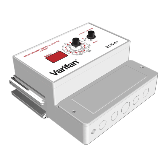
- Page 1 ECS-4+ USER’S GUIDE www.monitrol.com...
- Page 2 ECS-4+ Although the manufacturer has made every effort to ensure the accuracy of the information contained herein, this document is subject to change without notice due to ongoing product development. WARNINGS AND PRECAUTIONS Equipment, probe failure, blown fuses and/or tripped breakers may prove harmful to the contents of the building.
-
Page 3: Table Of Contents
TABLE OF CONTENTS CHAPTER 1 - INTRODUCTION General ................5 Description ...............5 Definition of terms .................7 CHAPTER 2 - INSTALLATION Unpacking ................9 Mounting ................9 Switch Settings ..............11 2.3.1 Line Voltage Selector Switch ..........11 2.3.2 Software Settings DIP Switch .........11 Connection Procedure ............12 2.4.1 Input Power ..............12 2.4.1.1 115 VAC ................12... - Page 4 ECS-4+ Heater/Fan 3 Relative Set Point ........26 Air Inlet Relative Set Point ..........27 Air Inlet Static Pressure Set Point ........28 Static Pressure Display ...........29 Reduction per Day ............30 Record Low Temperature ..........31 Record High Temperature ..........32 Room Temperature Display ..........33 SECONDARY FUNCTIONS Fan 1 Motor ..............34 Fan 1 Differential .............35...
-
Page 5: Chapter 1 - Introduction
CHAPTER 1 - INTRODUCTION 1. GENERAL This document provides a description of the ECS 4+ control. This document is organized as follows: • Introduction • Installation • User’s Guide • Appendix 1.1 DESCRIPTION Congratulations on the purchase of your ECS 4+ environmental control system. - Page 6 ECS-4+ The second stage provides control over a second variable speed fan. This second stage is also fully programmable for settings such as minimum speed, relative set point, etc. The third stage controls either a heater for colder climates, or a third single speed fan where additional cooling is required.
-
Page 7: Definition Of Terms
CHAPTER 2 - INSTALLATION MAIN SET POINT The desired room temperature. Other temperature settings on the ECS-4+ are relative to the main set point temperature. RELATIVE SET POINT A value added to or subtracted from the main set point which results in a new temperature at which a desired action starts or stops. - Page 8 ECS-4+ Page 8 www.monitrol.com...
-
Page 9: Unpacking
CHAPTER 2 - INSTALLATION Chapter 2 describes the installation of the ECS-4+control. The manufacturer recommends that the installation instructions which follow be adhered to as closely as possible, and all work be performed by a certified electrician. Failure to do so may void the warranty! 2.1 UNPACKING... - Page 10 ECS-4+ Use a screwdriver to remove the lower terminal cover exposing two mounting holes located at the bottom left and right corners of the control panel box as shown in figure 1. A third mounting hole is located on the rear side of the control panel box.
-
Page 11: Switch Settings
CHAPTER 2 - INSTALLATION 2.3 SWITCH SETTINGS The ECS-4+ is configured for a variety of options via two switches: the line voltage selector switch, and the software settings DIP switch. These switches are described in the following two sections. 2.3.1 - Line Voltage Selector Switch This switch is located on the surface of the main (bottom) board and adapts the control panel for 115 VAC or 230 VAC line voltage. -
Page 12: Connection Procedure
ECS-4+ 2.4 CONNECTION PROCEDURE For the connection procedures which follow refer to Figures 2 through 6. 2.4.1 - Input power To facilitate the installation work, the unit is shipped with two cable knock-outs removed. If two cable paths are not sufficient, remove other cable knock-outs with a... -
Page 13: Air Inlet Baffle Board
CHAPTER 2 - INSTALLATION 2.4.5 - Air Inlet Baffle Board Stage 4 provides two dry contact which control a linear actuator motor used to operate an air inlet baffle board. One dry contact closure is used to operate the motor winding which extends the actuator arm outwards, and one dry contact closure is used to operate the motor winding which retracts the actuator arm inwards. -
Page 14: Alarm
ECS-4+ 2.6 ALARM The ECS 4+ provides a normally open and normally closed dry contact for alarming low or high temperature conditions. In addition, this same contact can be used to signal a power failure. This contact may be connected to an alarm system, or directly to a siren and/or auto-dialer. - Page 15 CHAPTER 2 - INSTALLATION Figure 2 Two fans, one actuator and one heating unit Notes for Figures 2 and 6 Power cut and protection devices in case of overload. Only use fans that have thermal protection devices. Terminals 8, 10, and 11 are internally connected. Connect the ground wire to ground terminal 13.
- Page 16 ECS-4+ Figure 3 Probes and Alarm Wiring Figure 4 Temperature Averaging Probe connections Page 16 www.monitrol.com...
- Page 17 CHAPTER 2 - INSTALLATION Figure 5 Main Board: Terminal block, switches, fuses and ground. Page 17 www.monitrol.com...
- Page 18 ECS-4+ Figure 6 Recommended control backup Page 18 www.monitrol.com...
-
Page 19: Chapter 3 - User's Guide
CHAPTER 3 - USER’S GUIDE The ECS 4+ front panel shown above features a LED status window and two control dials which are respectively used to select a function and adjust a setting. LED STATUS WINDOW The LED status window features a 3 digit LED readout for the display of temperature in Fahrenheit or Celsius, pressure level, and programmable settings. - Page 20 ECS-4+ Fan 2 minimum speed Heater/Fan 3 relative set point temperature Either the air inlet relative temperature, or the air inlet static pressure set point Static room pressure display Ramping Record low temperature display Record high temperature display Room temperature display Any one of these functions is selected by rotating the Selector dial to the corresponding number and associated graphical image printed on the faceplate of the panel.
-
Page 21: Primary Functions
CHAPTER 3 - USER’S GUIDE PRIMARY FUNCTIONS MAIN SET POINT TEMPERATURE The main set point establishes the target temperature in the building. This value is used as the reference point for other temperature settings. The main set point temperature is adjusted in 0.5 degree increments from a minimum setting of 42.0°F (5.5°C) to a maximum setting of 111°F (44.0°C). -
Page 22: Fan 1 Minimum Speed
ECS-4+ FAN 1 MINIMUM SPEED This function sets the minimum speed of Fan 1 when room temperature is below the main setpoint. This value is entered as a percentage of maximum speed. The Fan 1 minimum speed is adjusted in 2% increments from a minimum setting of 12% to a maximum setting of 100%. -
Page 23: Fan 1 Duty Cycle
CHAPTER 3 - USER’S GUIDE FAN 1 DUTY CYCLE As long as the actual temperature is below the main set point, Fan 1 operates at the minimum speed, set by Fan 1 minimum speed (primary function 2). The Fan 1 duty cycle sets the percentage of time the fan is ON versus the percentage of time the fan is OFF. -
Page 24: Fan 2 Relative Set Point
ECS-4+ FAN 2 RELATIVE SET POINT The Fan 2 relative set point establishes the temperature above the main set point at which Fan 2 begins to operate at its minimum speed. The value is a temperature difference from the main set point. The Fan 2 relative set point is adjusted in 0.5 degree increments from a minimum setting of 0.0°F (0.0°C) to a maximum setting of 18.0°F... -
Page 25: Fan 2 Minimum Speed
CHAPTER 3 - USER’S GUIDE FAN 2 MINIMUM SPEED When the room temperature is at the Fan 2 relative set point, Fan 2 runs at minimum speed set by this function. This value is entered as a percentage of maximum speed. The Fan 2 minimum speed is adjusted in 2% increments from a minimum setting of 12% to a maximum setting of 100%. -
Page 26: Heater/Fan 3 Relative Set Point
ECS-4+ HEATER / FAN 3 RELATIVE SET POINT The Heater/Fan 3 relative set point is the relative set point at which Heater/Fan 3 begins to operate. This value is the temperature difference from the main set point. When a heater is being controlled, the relative set point is below the main set point. -
Page 27: Air Inlet Relative Set Point
CHAPTER 3 - USER’S GUIDE AIR INLET RELATIVE SET POINT The air inlet relative set point establishes the relative temperature at which the actuator motor begins to open or close the air inlet baffle board. This value is a temperature difference from the main set point. -
Page 28: Air Inlet Static Pressure Set Point
ECS-4+ AIR INLET PRESSURE SET POINT inlet static pressure point establishes the desired room static pressure level. When the room static pressure rises above the static pressure set point, the air inlet baffle board begins to open. When the static pressure of the room drops below the static pressure set point, the air inlet baffle board begins to close. -
Page 29: Static Pressure Display
CHAPTER 3 - USER’S GUIDE STATIC PRESSURE DISPLAY This function displays the static pressure level of the room. Static pressure is displayed in 0.01” H increments from a minimum display of -20” O , to a maximum display of 20” H O . -
Page 30: Reduction Per Day
ECS-4+ REDUTION PER DAY The reduction per day function automatically reduces the main set point by the set amount every 24 hours. The reduction setting is adjusted in 0.01 degree decrements from a minimum setting of OFF, -0.01°F (-0.01°C) to a maximum setting of -0.99°F (-0.50°C). -
Page 31: Record Low Temperature
CHAPTER 3 - USER’S GUIDE RECORD LOW TEMPERATURE This function displays the lowest recorded temperature since the last clear. The record low temperature is rounded to the nearest 0.5 degree from a minimum display of 42.0°F (5.5°C) to a maximum display of 111°F (44.0°C). -
Page 32: Record High Temperature
ECS-4+ RECORD HIGH TEMPERATURE This function displays the highest recorded temperature since the last clear. The record high temperature is rounded to the nearest 0.5 degree from a minimum display of 42.0°F (5.5°C) to a maximum display of 111°F (44.0°C). If a temperature higher than 111°F is recorded, Hi is displayed. -
Page 33: Room Temperature Display
CHAPTER 3 - USER’S GUIDE ROOM TEMPERATURE DISPLAY This function displays the room temperature. The Selector dial should normally be left in this position. The room temperature is displayed to the neerest 0.5 degree from a minimum display of 42.0°F (5.5°C) to a maximum display of 111°F (44.0°C) If the temperature is lower than 42.0°F,... -
Page 34: Fan 1 Motor
ECS-4+ FAN 1 MOTOR The Fan 1 motor compatibility setting adjusts the control panel outputs to the electrical characteristics of the fan motor. Six choices are available. Using the compatibility table in the Appendix, find the model number of your fan motor and Motor take note of the fan motor compatibility number. -
Page 35: Fan 1 Differential
CHAPTER 3 - USER’S GUIDE FAN 1 DIFFERENTIAL The Fan 1 differential setting establishes the temperature at which Fan 1 reaches maximum speed. The value entered is the temperature difference from the main set point. The Fan 1 diferential is adjusted in 0.5 degree increments from a minimum setting of 2.0°F Diff (1.0°C) to a maximum setting of 18°F (10.0°C). -
Page 36: Fan 2 Differential
ECS-4+ FAN 2 DIFFERENTIAL The Fan 2 differential setting establishes the temperature at which Fan 2 reaches maximum speed. The value entered is the temperature difference above the Fan 2 relative set point. Diff The Fan 2 diferential is adjusted in 0.5 degree increments from a minimum setting of 2.0°F (1.0°C) to a maximum setting of 18°F (10.0°C). -
Page 37: Fan 2 Motor
CHAPTER 3 - USER’S GUIDE FAN 2 MOTOR The Fan 2 motor compatibility setting adjusts the control panel outputs to the electrical characteristics of the fan motor. Six choices are available. Using the compatibility table in the Appendix, Moteur find the model number of your fan motor and take note of the fan motor compatibility number. -
Page 38: Heater/Fan 3 Hysteresis
ECS-4+ HEATER/FAN 3 HYSTERESIS In order to minimize erratic behavior of Heater/Fan 3 when room temperature is exactly at the relative set point, the hsteresis setting separates this ON/OFF threshhold into two: one ON threshhold and one OFF. This feature greatly reduces equipment wear. Hyst. -
Page 39: Air Inlet Run Timer
CHAPTER 3 - USER’S GUIDE AIR INLET RUN TIMER The air inlet run timer establishes the period of time that the actuator motor operates when opening or closing the air inlet baffle board. The air inlet run timer is adjusted in 1 second increments from a minimum setting of 1 second Run Time to a maximum setting of 60 seconds. -
Page 40: Air Inlet Delay Timer
ECS-4+ AIR INLET DELAY TIMER The air inlet delay timer establishes the delay time before the actuator motor begins to operate. The air inlet delay timer is adjusted in 1 minute increments from a minimum setting of 1 Delay minute to a maximum setting of 20 minutes. Adjusting the air inlet delay timer: •... -
Page 41: Minimum Ramping
CHAPTER 3 - USER’S GUIDE MINIMUM RAMPING Minimum ramping is the lowest that the ramping function can adjust the main set point to. This is a safety feature. The minimum ramping setting is adjusted in 0.5 degree increments from a minimum setting of Limit 42.0°F (5.5°C) to a maximum setting of 111°F (44.0°C). -
Page 42: Low Temperature Alarm
ECS-4+ LOW TEMPERATURE ALARM This function establishes the temperature difference below the main set point that the room can reach before a low temperature alarm is triggered. When a low temperature alarm occurs, an alarm contact is activated and the alarm LED segment lights up on the Alarm panel. -
Page 43: High Temperature Alarm
CHAPTER 3 - USER’S GUIDE HIGH TEMPERATURE ALARM This function establishes the temperature difference above the main set point that the room can reach before a high temperature alarm is triggered. When a high temperature alarm occurs, an alarm contact is activated and the alarm LED segment lights up on the Alarm panel. -
Page 44: Motor Compatibility Table
ECS-4+ MOTOR COMPATIBILITY TABLE CURVE BRAND MODEL VOLT SIZE Multifan 4E40 230 v. 16” Multifan 2E20 8” Multifan 4E35 230 v 14” Multifan 4E40 115 v. 16” Multifan 4E45 115 v. 18” Multifan 4E50 115 v. 20” Multifan 4E50 230 v. 20”... -
Page 45: Toubleshooting
APPENDIX TROUBLESHOOTING SYMPTOM CAUSE and REMEDY − Lo is Temperature is below minimum 42.0°F continually ° (5.5 − displayed Probe is disconnected or defective. − Hi is Temperature is above maximum 111°F continually (42°C). − displayed Probe is short circuited. −... -
Page 46: Specifications
ECS-4+ SPECIFICATIONS DESCRIPTION VALUE − INPUT POWER 12 AMP inductive − 115/230 -20%, +10% VAC − 50 / 60 Hz − STAGE 1 (variable speed) 6 AMP; inductive 115V / 230V − 10 AMP; max (fuse 10A) − STAGE 2 (variable speed) 6 AMP;... -
Page 47: Warranty
Limited Warranty manufacturered equipment supplied components have gone through rigorous inspection to assure optimal quality of product and reliability. Individual controls are factory tested under load, however the possibility of equipment failure and/or malfunction may still exist. For service, contact your local retailer or supplier. The warranty period shall be for two years from manufacturing date. - Page 48 MAV ECS4+ V2.1 July 2001 www.monitrol.com...
Need help?
Do you have a question about the ECS-4+ and is the answer not in the manual?
Questions and answers