Table of Contents
Advertisement
Installation Guide
IC-68
Intelligent Control
CONFIGURATION
1 Parameter 1
1
2 Param
eter
2
2
3 Param
eter
3
3
4 Param
eter
4
4
5 Param
eter
5
5
6 Param
eter
6
6
7 Param
eter
7
7
8 Param
eter
8
8
9 Param
eter
9
9
10 Param
eter
10
10
11 Param
eter
11
11
12 Param
eter
12
12
13 Param
eter
13
13
14 Param
eter
14
14
15 Param
eter
15
15
16 Param
eter
16
16
17 Param
eter
17
17
18 Param
eter
18
18
19 Param
eter
19
19
20 Param
eter
20
20
www.monitrol.com
ND
7 5 . 7
1 Output 1
2
Output
2
3
Output
3
4
Output
4
5
Output
5
6
Output
6
7
Output
7
8
Output
8
9
Output
9
10
Output
10
Advertisement
Table of Contents

Related Manuals for Varifan IC-68ND


Summary of Contents for Varifan IC-68ND
- Page 1 Installation Guide IC-68 Intelligent Control 7 5 . 7 CONFIGURATION 1 Parameter 1 2 Param eter 1 Output 1 3 Param eter 4 Param eter Output 5 Param eter Output 6 Param eter 7 Param eter Output 8 Param eter 9 Param eter Output...
- Page 2 IC-68 INSTALLATION GUIDE WARNINGS AND PRECAUTIONS Although the manufacturer has made every effort to ensure the accuracy of the information contained herein, this document is subject to change without notice due to ongoing product development. WARNINGS AND PRECAUTIONS Defective equipment, probe failure, blown fuses and/or tripped breakers may prove harmful to the contents of the building.
-
Page 3: Table Of Contents
IC-68 INSTALLATION GUIDE TABLE OF CONTENTS Unpacking ..........................3 Mounting Hardware Required..................... 3 General installation guidelines................... 4 IC-68 Control ......................4 Electrical Cables......................4 Electrical Power......................4 Mounting..........................5 Control Description ......................6 Connection Procedure ......................8 General Wiring Diagram ....................8 Detailed Wiring Diagrams.................... -
Page 4: Unpacking
IC-68 INSTALLATION GUIDE The purpose of this guide is to fully inform the electrician on proper wiring and installation procedures for the IC-68 . Full conformity of the Installation and User’s Guide will lead to a successful installation and proper functioning of the IC-68 control . -
Page 5: General Installation Guidelines
IC-68 INSTALLATION GUIDE 3. General installation guidelines 3.1 IC-68 Control • It is recommended to install the unit in a hallway to limit the IC-68 ’s exposure to noxious gases. • In order to avoid condensation problems inside the controller, it is recommended to install the IC-68 on an inside wall. -
Page 6: Mounting
IC-68 INSTALLATION GUIDE 4. Mounting • Use a screwdriver to remove the 4 screws from the top of the faceplate and the 2 screws on the access panel. • Open both faceplates. • Install mounting screw on wall and hang the unit in place by sliding the rear mounting hole of the IC-68 over the screw (see figure 1). -
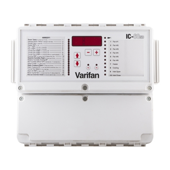
Page 7: Control Description
IC-68 INSTALLATION GUIDE 5. Control Description FIGURE NO. 2 The IC-68 Control FRONT VIEW 7 5 . 7 CONFIGURATION 1 Parameter 1 2 Parameter 2 1 Output 1 3 Parameter 3 Output 4 Parameter 4 5 Parameter 5 Output 6 Parameter 6 7 Parameter 7 8 Parameter 8 Output... -
Page 8: Figure No. 3 Ic-68 Nd Electronic Main Board
IC-68 INSTALLATION GUIDE FIGURE NO. 3 IC-68 Electronic Main Board 0.125A 250V 250V Slo-Blo Slo-Blo FAST- ACT- PRB1 PRB2 PRB3 PRB4 PRB5PRB6 (4-20mA) TO POWER SOURCE www.monitrol.com... -
Page 9: Connection Procedure
IC-68 INSTALLATION GUIDE 6. Connection Procedure 6.1 General Wiring Diagram Since the IC-68 is a configurable control, the specific wiring diagram comes with the User’s Guide particular to this installation. 6.2 Detailed Wiring Diagrams 6.2.1 Typical Sensor Wiring for Probes The inside temperature sensor should be located in the area which gives the most accurate temperature reading to achieve optimum ventilation. -
Page 10: Typical Power Backup Wiring
IC-68 INSTALLATION GUIDE 6.2.2 Typical Power Backup Wiring A backup relay (DPDT) connects to the power source 1 in normal operation but will switch to the power source 2 if source 1 is disabled. The backup relay must be selected to ensure it is able to support the required power load. -
Page 11: Typical Thermostat Backup Wiring
IC-68 INSTALLATION GUIDE 6.2.3 Typical Thermostat Backup Wiring If the Intelligent Control or a module fails, the backup thermostats will activate the dedicated fan or heater as soon as temperature reaches the set point of the thermostat. The thermostat must be accessible for adjustment and must be set at 3 to 5 degrees above the fan’s relative set point or 3 to 5 degrees under the heater relative set point. -
Page 12: Figure No. 7 Typical Thermostat Backup Wiring On Variable Stage
IC-68 INSTALLATION GUIDE FIGURE NO. 7 Typical Thermostat Backup Wiring on variable stage www.monitrol.com... -
Page 13: Powering Up Procedure
IC-68 INSTALLATION GUIDE Typical Alarm Connection Wiring The IC-68 provides a normally close dry contact to set off an alarm (high or low temperature, power or control failure, …). Is strongly recommended to connect the alarm relays to an alarm system or an auto-dialer. -
Page 14: Download The Configuration (If Necessary)
IC-68 INSTALLATION GUIDE 7.3 Download the Configuration (if necessary) When upgrading your system with a new configuration, you will have to download the configuration. a) Ensure the power source of the IC-68 is OFF (flip the circuit breaker on the distribution panel). -
Page 15: Troubleshooting
IC-68 INSTALLATION GUIDE 7.5 Troubleshooting SYMPTOM CAUSE REMEDY Temperature probe reads Temperature is below -6°F Check all connections. If the (-21°C). problem persists, Probe disconnected temperature within normal defective. range, replace the probe. Check all connections. If the Temperature probe reads Temperature is above 168°F (76°C). -
Page 16: Nd Compatible Probes
Relative humidity probe RH-3 Universal relative humidity probe with a measuring range of 0 to 100 %. • After market probe (Non Varifan probes) The IC-68 is compatible with resistive type (potentiometer, on/off switch), voltage type, 4 to 20 mA type (you have to put on jumper JP1 for PRB5 or JP2 for PRB6) and pulse type (water and feeder counter). -
Page 17: Specifications
IC-68 INSTALLATION GUIDE • The 8 Relay Board uses an 1126A board • The Typical ON/OFF Outputs Board uses an 1120A board • The Toggles For Inlets uses an 1121A board 8. Specifications DESCRIPTION VALUE Input Power 12 W max Power Source (line) 115/230 VAC, -20%, +10% 50/60 Hz... -
Page 18: Limited Warranty
MAV IC-68ND VER:1.0 October 3, 2003 www.monitrol.com...
Need help?
Do you have a question about the IC-68ND and is the answer not in the manual?
Questions and answers