Table of Contents
Advertisement
Quick Links
Advertisement
Table of Contents

Subscribe to Our Youtube Channel
Related Manuals for Varifan MSC-10


Summary of Contents for Varifan MSC-10
- Page 1 MSC-10 Varifan MSC-10 User’s Guide Page 1 www.monitrol.com...
- Page 2 MSC-10 Although the manufacturer has made every effort to ensure the accuracy of the information contained herein, this document is subject to change without notice due to ongoing product development. WARNINGS AND PRECAUTIONS Equipment , probe failure, blown fuses and/or tripped breakers may prove harmful to the contents of the building.
-
Page 3: Table Of Contents
Figure 2-2 Typical Sensor Probe Wiring ..........11 Figure 2-3 Enclosure Mounting Hole Locations ........15 Figure 2-4 Installation Set-up ............... 16 Figure 2-5 Main Board Layout and Connections ........17 Figure 3-1 MSC-10 Main Components ..........19 Page 3 www.monitrol.com... - Page 4 MSC-10 Page 4 www.monitrol.com...
-
Page 5: Chapter 1 - Introduction
This instruction manual is provided for the installation and operator personnel of the Varifan Multistage Computer (MSC-10). The MSC-10 is a modular control unit which uses an advanced digital control system. The MSC-10 is considered a “master control unit” and can control and monitor up to 4 modules of two stages each, as follows: •... - Page 6 Multistage ventilation / heating / sprinkler systems • Combined natural and forced ventilation systems • Room ventilation systems The MSC-10 can be integrated in a fully automated system using its built-in program with 3 categories of control modules. • Control Module •...
-
Page 7: Chapter 2 - Installation Guidelines And Safety Procedures
Set the line voltage switch inside the MSC-10 to the correct value before attempting to operate the multistage computer. Ensure that the same phases supplying the MSC-10 are the same as the two power lines of the variable fan (s). Otherwise the control signal of the MSC-10 will be too early or too late and the fan will not rotate as expected. - Page 8 MSC-10 Electrical Grounding. The shields of all cables should be connected the MSC-10 power ground only, except for the cable connected to a PC interface (PCI-20 or RCM-40) where the shield should be connected as instructed in the PCI-20 or RCM-40 document.
-
Page 9: Figure 2-1 Safety Control Backup Wiring (2 Sheets)
Chapter 2 - Installation MSC-10 Figure 2-1 (Sheet 1 of 2) Safety Control Backup Wiring MSC POWER INPUT DISTRIBUTION DISTRIBUTION PANEL PANEL If the 115 LINE LINE VAC line is 230 VAC 230 VAC used, then source 2 source 1... - Page 10 Chapter 2 - Installation MSC-10 Figure 2-1 (Sheet 2 of 2) Safety Control Backup Wiring MSC OUTPUT MST-1 T15-WD BACK-UP THERMOSTAT The MST-1 provides an Alarm Relay in addition. Page 10 www.monitrol.com...
-
Page 11: Figure 2-2 Typical Sensor Probe Wiring
Chapter 2 - Installation MSC-10 Figure 2-2 Typical Sensor Probe Wiring WIRE CONNECTOR SHIELD POWER GROUND PROBE TYPICAL SINGLE PROBE POWER GROUND It is recommended to solder the junctions of the probes. TYPICAL 4 PROBES WIRING Page 11 www.monitrol.com... -
Page 12: Guidelines For Modules And Sensors
Control modules can be placed either near the equipment they control, such as fans and curtain machines or in a central area close to the MSC-10 module. Inside Temperature Sensor Probe. The inside temperature sensor probe should be located in an area which gives the most accurate temperature reading to achieve optimum ventilation. -
Page 13: Unpacking The Msc-10
(see Figure 2-3). Remove the screws ( see Figure 2-4 (1)) securing the front panel (2) and the screws securing the lower access plate. Install the MSC-10 computer on a wall or suitable area and secure it with attaching hardware and perform the following: Ensure the ribbon cable (3) is properly connected. - Page 14 Install the CONTROL VALUES label (5) and the OUTPUTS label (4) into their appropriate slot of the front panel. Before proceeding to the configuration setup of your installation, review the User Guide in Chapter 3 for the control descriptions of the MSC-10 computer. Page 14 www.monitrol.com...
-
Page 15: Figure 2-3 Enclosure Mounting Hole Locations
Chapter 2 - Installation MSC-10 Figure 2-3 Enclosure Mounting Hole Locations TOP MOUNTING HOLE BOTTOM MOUNTING HOLE BOTTOM MOUNTING HOLE REAR VIEW Page 15 www.monitrol.com... -
Page 16: Figure 2-4 Installation Set-Up
Chapter 2 - Installation MSC-10 Figure 2-4 Installation Set-up DETAIL A SCREWS (4) FRONT PANEL RIBBON CABLE OUTPUTS LABEL CONTROL VALUES LABEL CUTOUT LABEL INPUT SLOT ACCESS HOLE Page 16 www.monitrol.com... -
Page 17: Figure 2-5 Main Board Layout And Connections
Chapter 2 - Installation MSC-10 Figure 2-5 Main Board Layout and Connections Page 17 www.monitrol.com... -
Page 18: Chapter 3 - User Guide
Control values label (12) and the outputs label (5), allow the operator to view the inputs and outputs of the MSC-10 computer. Up arrow button (14) and down arrow button (13), allow the operator to select a control value LED indicator. -
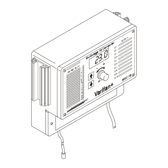
Page 19: Figure 3-1 Msc-10 Main Components
Chapter 3 - User’s Guide MSC-10 Figure 3-1 MSC-10 Main Components 1 ACCESS PLATE 2 SCREW (2) 3 DIGITAL DISPLAY 4 FRONT PANEL 5 OUTPUTS LABEL 6 SCREW (4) 7 HEAT SINK (2) 8 ADJUST KNOB 9 CONFIG MODULE STORAGE LOCATION... -
Page 20: Operating Instructions
DOWNLOADING A NEW CONFIGURATION The procedure to download a new configuration to the MSC-10 computer is as follows (see Figure 3-1): Turn off the power source to the MSC-10 (flip the circuit breaker on the power distribution panel). Page 20... -
Page 21: List Of Abbreviations
LIST OF ABBREVIATIONS MSC-10 Remove the screws (2) and the access plate (1) of the MSC-10. Locate the configuration module (10) and insert the config module into the socket on the main board. Ensure the arrow of the config module is pointing the same way as shown on the main board. -
Page 22: Specifications
MSC-10 SPECIFICATIONS DESCRIPTION VALUE − INPUT POWER 12 W max. − 115/230 -20%, +10% VAC − 50 / 60 Hz − NOT FUSED − STAGES 1 and 2 10 AMP; 115V/230V AC only − (variable , fused) Min. Rating 150mA AC only −... -
Page 23: Limited Warranty
MSC-10 Limited Warranty manufacturered equipment supplied components have gone through rigorous inspection to assure optimal quality of product and reliability. Individual controls are factory tested under load, however the possibility of equipment failure and/or malfunction may still exist. For service, contact your local retailer or supplier. The... - Page 24 MSC-10 MAVMSC-10 Ver. 1.01 July 95 Rev.: June, 2001 Main board Page 24 www.monitrol.com...
Need help?
Do you have a question about the MSC-10 and is the answer not in the manual?
Questions and answers