
Related Manuals for Varifan ECS-1M


Summary of Contents for Varifan ECS-1M
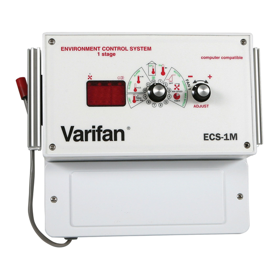
- Page 1 ECS-1M USER’S MANUAL ENVIRONMENT CONTROL SYSTEM 1 stage computer compatible DIFF MIN SPEED reduc. per day TIMER ADJUST Varifan ® ECS-1M Page 1 www.monitrol.com...
- Page 2 ECS 1M Although the manufacturer has made every effort to ensure the accuracy of the information contained herein, this document is subject to change without notice due to ongoing product development. WARNING AND PRECAUTIONS Equipment, probe failure, blown fuses and/or tripped breakers may prove harmful to the contents of the building.
-
Page 3: Table Of Contents
TABLE OF CONTENTS CHAPTER 1 - INTRODUCTION General ................5 Description ...............5 Definition of terms .................7 CHAPTER 2 - INSTALLATION Unpacking ................9 Mounting ................10 Switch Settings ..............10 2.3.1 Line Voltage Selector Switch ..........10 2.3.2 Software Settings Switch ..........11 Connection Procedure ............11 2.4.1 Input Power ..............11 2.4.1.1 115 VAC ................11... - Page 4 ECS 1M CONTENTS CONTINUED... Ramping ................. 27 Record Low Temperature ..........28 Record High Temperature ..........29 Ambient Room Temperature Display ......30 SECONDARY FUNCTIONS Relative Humidity Set Point ..........31 Fan 1 Motor ..............32 Fan 1 Minimum Humidity Speed ........33 Fan 1 Maximum speed ...........
-
Page 5: Chapter 1 - Introduction
CHAPTER 1 - INTRODUCTION 1. GENERAL This document provides a description of the ECS 1M control panel. This document is organized as follows: Introduction Installation User’s Guide Appendix 1.1 DESCRIPTION Congratulations on the purchase of your ECS 1M environmental control system. The ECS M product line provides you with full control over temperature, humidity, air flow, and heat resulting in a comfortable environment for your livestock. - Page 6 ECS 1M DESCRIPTION CONTINUED... The ECS 1M provides you with full control over one stage via the use of an easy to follow display panel. All programmable features can be customized to meet your requirements. The ECS 1M keeps you constantly informed by displaying the status of all of its outputs as well as the ambient temperature.
-
Page 7: Definition Of Terms
DEFINITION OF TERMS MAIN SET POINT The desired room temperature. Other temperature settings on the ECS 1M are relative to the main set point temperature. RELATIVE TEMPERATURE A value added to or subtracted from the main set point which results in a new temperature at which a desired action starts or stops. - Page 8 ECS 1M Page 8 www.monitrol.com...
-
Page 9: Chapter 2 - Installation
CHAPTER 2 - INSTALLATION Chapter 2 describes the installation of the ECS 1M control panel. The manufacturer recommends that the installation instructions which follow be adhered to as closely as possible, and all work be performed by a certified electrician. Failure to do so may void the warranty! 2.1 UNPACKING Unpack the ECS 1M from its box and inspect contents for damage. -
Page 10: Mounting
ECS 1M 2.2 MOUNTING To limit the unit’s exposure to noxious gases install the unit in a hallway. Make certain that the unit is mounted right side up with the cable entry holes facing down. The ECS 1M will operate in a temperature range of 32°F - 120 °F (0 °C - 50 °C). -
Page 11: Software Settings Switch
CHAPTER 2 - INSTALLATION 2.3.2 - Software Settings Switch This switch is located at the rear of the control panel faceplate and adjusts the following options. Fahrenheit Celsius Settings locked Setting unlocked When used with a DIP-1 Relative Humidity Switch 1 Selects between a Fahrenheit or Celsius display on the front panel. -
Page 12: 230 Vac
ECS 1M 2.4.1.2 - 230 VAC Make certain that the line voltage selector switch is set to 230 VAC. Connect the power cable to terminals 5 and 6 on the main (bottom) board, connect the ground wire to terminal 7 on the main board. -
Page 13: Single Temperature Probe
CHAPTER 2 - INSTALLATION Use shielded cabling for probes . Connect the shields to “SHLD” terminal. Failure to do so may result in inaccurate readings! 2.5.1 Single Temperature Probe Install a single temperature probe in an area that best reflects the overall temperature of the room. Connect the two leads and the shield of the temperature probe to the control panel terminals labelled “Probe”... -
Page 14: Powering Up
ECS 1M 2.7 POWERING UP Before powering up the ECS 1M, attach the faceplate to the casing of the control panel using the six screws previously removed. Set Selector knob to position (12). Upon power up, the unit will test it’s display by briefly lighting all the segments of it’s LED. - Page 15 CHAPTER 2 - INSTALLATION Fig. 2 One Fan (230V) Notes for Figures 1, and 2 Power cut and protection devices in case of overload. Only use fans that have thermal protection devices. Terminals 4 and 5 are internally connected. Connect the grounding wire to the ground terminal 7 . Page 15 www.monitrol.com...
- Page 16 ECS 1M Fig. 3. Probes and Alarm Wiring Fig. 4 Temperature Averaging Probe Connection Page 16 www.monitrol.com...
- Page 17 CHAPTER 2 - INSTALLATION Fig. 5 Main Board: Terminal, Blocks, Switches, Fuses and Ground Ground Connection EPM-10 Alarm Probes 1054 Page 17 www.monitrol.com...
- Page 18 ALARM CIRCUIT. In normal operation, the alarm circuit of the Varifan Control is a short circuit. But if the Varifan control is defective or if there is no power applied to it, then the alarm circuit of the control will be an open circuit.
- Page 19 CHAPTER 2 - INSTALLATION Fig 6. Recommended control backup Page 19 www.monitrol.com...
- Page 20 ECS 1M Page 20 www.monitrol.com...
-
Page 21: Chapter 3 - User Guide
CHAPTER 3 - USER GUIDE The ECS 1M front panel shown above features a LED status window control dials which respectively used to select a function and adjust a setting. LED STATUS WINDOW The LED status window features a 3 digit LED readout for the display of temperature in Fahrenheit or Celsius, humidity level, and programmable settings. - Page 22 ECS 1M The 8 primary functions are: 1 Main set point temperature 2 Fan 1 differential temperature 3 Fan 1 minimum speed 4 Fan 1 duty cycle timer 9 Ramping 10 Record low temperature display 11 Record high temperature display 12 Ambient temperature display Any one of these functions is selected by rotating the Selector dial to the corresponding number and associated...
-
Page 23: Main Set Point Temperature
CHAPTER 3 - USER GUIDE PRIMARY FUNCTIONS MAIN SET POINT The main set point establishes the target temperature in the building. This value is used as the reference point for other settings. The main set point temperature is adjusted in 0.5 degree increments from a minimum setting of 13.5°F (-9.5°C) to a maximum setting of 105.0°... -
Page 24: Fan 1 Differential
ECS 1M FAN 1 DIFFERENTIAL The Fan 1 differential setting establishes the temperature at which Fan 1 reaches maximum speed. The value is a temperature difference from the main set point. The Fan 1 differential is adjusted in 0.5 degree increments from a minimum setting of 2.0°F (1.0°C) to a maximum setting of 18.0°F (10.0°... -
Page 25: Fan 1 Minimum Speed
CHAPTER 3 - USER GUIDE FAN 1 MINIMUM SPEED This function sets the minimum speed of Fan 1 when room temperature is below the main set point. This value is entered as a percentage of fan maximum speed. The Fan 1 minimum speed is adjusted in 2% increments from a minimum setting of 12% to a maximum setting of 100%. -
Page 26: Fan 1 Duty Cycle
ECS 1M FAN 1 DUTY CYCLE As long as the actual temperature is below the main set point, Fan 1 operates at the minimum speed set by Fan 1 Minimum Speed (primary function 3). The Fan 1 duty cycle sets the per- centage of time the fan is ON versus the percentage of time the fan is OFF. -
Page 27: Ramping
CHAPTER 3 - USER GUIDE RAMPING The ramping function automatically reduces the main set point by the set amount every 24 hours. The ramping setting is adjusted in 0.01 degree decrements from a minimum setting of OFF, - 0.01°F (-0.01°C) to a maximum setting of - 0.99°F (-0.50°C) The main set point must be greater than the limit. -
Page 28: Record Low Temperature
ECS 1M RECORD LOW TEMPERATURE This function displays the lowest recorded temperature since the last clear. The record low temperature is rounded to the nearest 0.5 degree from a minimum display of 13.5°F (-10.0°C) to a maximum display of 105.0°F (40.5°C). If a temperature lower than 13.5°F is recorded, Lo is displayed. -
Page 29: Record High Temperature
CHAPTER 3 - USER GUIDE RECORD HIGH TEMPERATURE This function displays the highest recorded temperature since the last clear. The record high temperature is rounded to the nearest 0.5 degree from a minimum display of 13.5°F (-10.0°C) to a maximum display of 105.0°F (40.5°C). -
Page 30: Ambient Room Temperature Display
ECS 1M AMBIENT ROOM TEMPERATURE DISPLAY This function displays the ambient room temperature. The Selector dial should normally be left in this position. The ambient temperature is displayed to the nearest 0.5 degree from a minimum display of 13.5°F (-10.0°C) to a maximum display of 105.0°F (41.0°C). -
Page 31: Secondary Functions
CHAPTER 3 - USER GUIDE SECONDARY FUNCTIONS REATIVE HUMIDITY SET POINT If the ECS is equipped with an optional humidity sensor, this setting regulates the humidity level of the room. The humidity setting affects the operation of Fan 1 only. When the humidity level of the room exceeds the relative humidity setting, Fan 1 runs at a new minimum speed set by secondary function (3). -
Page 32: Fan 1 Motor
ECS 1M FAN 1 MOTOR The Fan 1 motor compatibility setting adjusts outputs electrical characteristics of the fan motor. Eight choices are available. If your motor is not listed in the compatibility table in the Appendix, try all choices and take the one that give the best performance with your fan. -
Page 33: Fan 1 Minimum Humidity Speed
CHAPTER 3 - USER GUIDE FAN 1 MINIMUM SPEED FOR HUMIDITY This function establishes the minimum speed of Fan 1 when the relative humidity level of the room exceeds the relative humidity setting. The speed setting for humidity must be configured higher than the speed setting for temperature. -
Page 34: Fan 1 Maximum Speed
ECS 1M FAN 1 MAXIMUM SPEED This function set the maximum speed of Fan 1 when room temperature is higher the main set point. This value is entered as a percentage of maximum speed. The Fan1 maximum speed is adjusted in 2% increments from a minimum of 60% to a maximum of 100%. -
Page 35: Minimum Ramping
CHAPTER 3 - USER GUIDE MINIMUM RAMPING Minimum ramping is the lowest that the ramping function can adjust the main set point to. This is a security feature. The minimum ramping setting is adjusted in 0.5 degree increments from a minimum setting Limit of 13.5°F (-9.5°C) to a maximum setting of 105.0°F (41.0°C). -
Page 36: Low Temperature Alarm
ECS 1M LOW TEMPERATURE ALARM This function establishes the temperature difference below the main set point that the room can reach before a low temperature alarm is signalled. When a low temperature alarm occurs an alarm contact is activated and the alarm LED lights on the front panel. -
Page 37: High Temperature Alarm
CHAPTER 3 - USER GUIDE HIGH TEMPERATURE ALARM This function establishes the temperature difference above the main set point that the room can reach before a high temperature alarm is signalled. When a high temperature alarm occurs an alarm contact is activated and the alarm LED lights on the front panel. -
Page 38: Relative Humidity Display
ECS 1M RELATIVE HUMIDITY DISPLAY This function displays the relative humidity of the room. Relative humidity displayed increments from a minimum display of 30% to a maximum display of 90%. If a humidity level lower than 30% is sensed, F2 is displayed. Conversely, if a humidity level higher than 90% is sensed, Hi is displayed. -
Page 39: Appendix
APPENDIX MOTOR COMPATIBILITY CURVE BRAND MODEL VOLT SIZE Multifan 4E40 230 v. 16” Multifan 2E20 8” Multifan 4E35 230 v 14” Multifan 4E40 115 v. 16” Multifan 4E40 230 v. 16” Multifan 4E45 115 v. 18” Multifan 4E45 230 v 18”... -
Page 40: Troubleshooting
ECS 1M TROUBLESHOOTING SYMPTOM CAUSE and REMEDY Lo is ° Temperature is below minimum (13.5 continually ° or -10.0 displayed Probe is disconnected or defective. Hi is Temperature above maximum continually (105.0°F or 41°C). displayed Probe is short circuited. Fan(s) or Verify whether the fan LED is on. -
Page 41: Specification
APPENDIX SPECIFICATION DESCRIPTION VALUE INPUT POWER 10 AMP 115/230 -20%, +10% VAC 50 / 60 Hz STAGE 1 (variable speed) 10 AMP; inductive 115V / 230V Fuse 15A ALARM (dry relay 2 AMP; 30V AC/DC contact) Page 41 www.monitrol.com... -
Page 42: Record Form
ECS 1M RECORD FORM Dial Option Default setting User setting Main Set Point Temperature 77°F 25°C Fan 1 Differential 4°F 2°C Fan 1 Min Speed Fan 1 Duty Cycle Timer Ramping 2nd Function Relative Humidity Fan 1 Motor Compatibility Fan 1 Min Speed For Humidity Fan 1 Maximum Speed 100% 100%... - Page 43 WARRANTY Limited Warranty manufacturered equipment supplied components have gone through rigorous inspection to assure optimal quality of product and reliability. Individual controls are factory tested under load, however the possibility of equipment failure and/or malfunction may still exist. For service, contact your local retailer or supplier. The warranty period shall be for two years from manufacturing date.
- Page 44 ECS 1M MAV ECS-1M Ver: 1.01 June 2001 Page 44 www.monitrol.com...
Need help?
Do you have a question about the ECS-1M and is the answer not in the manual?
Questions and answers