Table of Contents
Advertisement
Quick Links
Advertisement
Table of Contents

Related Manuals for TESTO 380


Summary of Contents for TESTO 380
- Page 1 380 - Fine particle analyzer Instruction manual...
-
Page 3: Table Of Contents
Particulate matter probe status display ............20 4.6.3. Measurement system status display .............. 20 4.6.3.1. Status display of the testo 330-2 LL V2010 (item no. 0632 3307) ..20 4.6.3.2. Status display of the testo 330-2 LL/F (item no. 0632 3305) .... 20 4.7. - Page 4 1 Contents Using the product ................. 31 6.1. Particle reading display ..............31 6.2. Conducting a measurement, testo 330-2 LL V2010 (0632 3307).. 32 6.2.1. Preparing for measurement ................32 6.2.2. Particle: test types – compliance measurement, adjustment help and approval test ....................
- Page 5 Accessories and spare parts ............80 8.3. Updating instrument software for testo 330-2 LL V2010 (0632 3307) ................... 82 8.4. Updating instrument software for testo 330-2 LL/F (0632 3305) ..82 8.5. Updating instrument software for testo 380 ........82...
-
Page 6: Safety And The Environment
2 Safety and the environment Safety and the environment 2.1. About this document > Please read this documentation through carefully and familiarize yourself with the product before putting it to use. Pay particular attention to the safety instructions and warning advice in order to prevent injuries and damage to the products. -
Page 7: Ensure Safety
Do not use any force. > The testo 380 must be checked for any visible damage before commissioning. Do not commission the testo 380 if there are any signs of damage on the housing, mains unit or supply lines. - Page 8 2 Safety and the environment > The objects to be measured or the measurement environment may also pose risks: Note the safety regulations valid in your area when performing the measurements. > The measurement system has been verified as a short-term measuring instrument and should not be used as a safety (alarm) instrument.
-
Page 9: Protecting The Environment
> Dispose of faulty rechargeable batteries/spent batteries in accordance with the valid legal specifications. > At the end of its useful life, send the product to the separate collection for electric and electronic devices (observe local regulations) or return the product to Testo for disposal. -
Page 10: Specifications
3 Specifications Specifications 3.1. The testo 380 must be used in conjunction with testo 330-2 LL. The designation testo 330-2 LL includes the measuring instrument • testo 330-2 LL/F, item no. 0632 3305 or • testo 330-2 LL V2010, item no. 0632 3307. - Page 11 3 Specifications The testo 380 is approved for fuels in accordance with instrument class A, B and C of VDI 4206-2. This corresponds to fuel groups 1 - 8 in accordance with § 3 of the first German Federal Imission Control Ordinance (BImSchV): 1.
-
Page 12: Declaration Of Conformity
3 Specifications 3.2.2. Declaration of Conformity... -
Page 13: Measuring Range, Accuracy And Resolution
Ambient humidity 0 to 90% RH, non-condensing Protection class IP40 Weight testo 380: 7.9 kg, testo 330: 0.65 kg Dimensions 475 mm x 360 mm x 190 mm (L x W x H) Housing material Power supply via the internal mains unit: 100 V AC/2.1 A - 240 V AC/ 0.95 A (50-60 Hz) -
Page 14: Other Instrument Data
Stainless steel 1,4301 Diameter of probe 12 mm shaft 3.2.7. Warranty Feature Values Warranty testo 380 with particulate matter probe: 24 months (excluding wear parts such as engines, pumps and filters) Sensor module: 12 months Terms of warranty see website www.testo.com/warranty... -
Page 15: Product Description
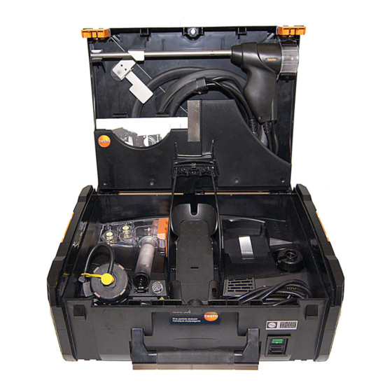
Instruction manual • testo 380 mains cable The testo 380 is delivered in a specially designed shipping carton in order to prevent damage during transport. Testo recommends keeping the packaging unit and using it again if you need to return the product. -
Page 16: Overview Of Testo 380
2 Particulate matter sensor with preheating section and pressure tube 3 Combustion air temperature probe connection 4 USB connection for updating the testo 380 5 Cotton filters incl. crude gas primary filter 6 Cleaning materials storage compartment 7 Fresh air filter... -
Page 17: Overview Of Particulate Matter Probe
13 Particulate matter probe (probe is permanently assigned to the measurement system) 14 Magnetic holder for the printer 15 Holder for testo 330 and securing clip for case lid 16 Printer (accessory) 17 Storage compartment 18 Storage compartment for the mains cable... -
Page 18: Overview Of Outlet Nozzles In The Testo 380
The cover cap on the test connection should only be removed for the gradient check. Removal of the cover cap outside of a gradient check will cause the testo 380 to malfunction. 2 Air inlet nozzle... -
Page 19: Overview Of Cleaning Material
3 Syringe with hose attachment 4 Cleaning box for the nozzle 4.6. Overview of status displays The status display indicates the operating status of the testo 380, the particulate matter probe and the measurement system. 4.6.1. testo 380 status display... -
Page 20: Particulate Matter Probe Status Display
Flashing red Fault 4.6.3. Measurement system status display 4.6.3.1. Status display of the testo 330-2 LL V2010 (item no. 0632 3307) The measurement system status display is indicated on the testo 330 display. 1 Measurement system status display Display Status Permanently green The system is ready for measurement. -
Page 21: Gas Path
4 Product description 4.7. Gas path Item / Designation Illustration 1 testo 330 2 Draught inlet 3 Adapter 4 Crude gas inlet... - Page 22 4 Product description Item / Designation Illustration 5 Fresh air inlet 6 Fresh air filter 7 Condensate container 8 Primary filter 9 Cotton filter 10 Secondary filter 11 Particulate matter probe socket 12 Crude gas inlet 13 Draught inlet 14 Crude gas path probe shaft 15 Probe shaft 16 Crude gas tube...
- Page 23 4 Product description Item / Designation Illustration 20 Preheating section 21 Particle sensor 22 Pressure tube 23 Measurement gas outlet nozzle 24 Test connection for the test bed...
-
Page 24: First Steps
330. 5.1.1. Checking the firmware version of the testo 330 In order to control the testo 380, the testo 330 used must have the following firmware version: • 0632 3305 firmware version V 2.0 onwards • 0632 3307 firmware version V 2.0 onwards... -
Page 25: Inserting The Testo 330
5 First steps 5.1.2. Inserting the testo 330 There is no need to switch off the testo 330 to insert it into the testo 380. 1. Fold up securing clip and click into place on the case lid. 2. Lift up the repository for the testo 330 and insert the measuring... -
Page 26: Connecting The Preheating Section
5 First steps 3. Insert the testo 330 into the holder and fix in place using the locking lever. 5.1.3. Connecting the preheating section 1. Remove the cover of the particulate matter sensor. 2. Put preheating section onto the particulate matter sensor and... -
Page 27: Connecting The Particulate Matter Probe
380 activation process. The particulate matter probe will not be detected by the testo 380 if it is not connected until after the testo 380 has been switched on or if it is disconnected from the testo 380 during a measurement. - Page 28 3. Connect up the particulate matter probe connections to the particulate matter sensor with preheating section (1) to the condensate container cotton filter (2) to the probe socket for the testo 380 (3). CAUTION Hot probe shaft due to automatic heat-up! Risk of burns! >...
-
Page 29: Using The Particulate Matter Probe
ATTENTION Backflow of condensate from the crude gas tube! Clogging of the rotation discs and damage to the testo 380. > Before removing the particulate matter probe from the flue gas duct, remove the crude gas tube from the particulate matter probe connection and dispose of the condensate in a suitable container. -
Page 30: Mains Operation
5 First steps 5.1.6. Mains operation > Connect the mains cable to the mains connection of the testo 380 and a mains socket with earthing contact. Power to the testo 330 is supplied via the testo 380. The rechargeable battery of the testo 330 is not charged while operated in conjunction with the testo 380. -
Page 31: Using The Product
6 Using the product Using the product 6.1. Particle reading display The measurement parameters for the Particle measurement type are predefined and cannot be adjusted. Overview of measurement parameters: Display Measurement parameter PMØ Mean value of the particulate mass since the start of the measurement PMØu Averaged end result dust less measurement... -
Page 32: Conducting A Measurement, Testo 330-2 Ll V2010 (0632 3307)
6 Using the product 6.2. Conducting a measurement, testo 330-2 LL V2010 (0632 3307) 6.2.1. Preparing for measurement The time required for an official measurement is approx. 30 min. If you switch to wood chips as fuel immediately following a... - Page 33 Tightness test For an official measurement, the tightness of the measurement system must be checked prior to every measurement. The locking lever for fixing the testo 330 in place must be closed. Call up function: > →...
-
Page 34: Particle: Test Types - Compliance Measurement, Adjustment Help And
Particle: test types – compliance measurement, adjustment help and approval test To prevent incorrect measurements, the position of the testo 380 and the particulate matter probe must not be changed during a measurement. For flue gas loss measurement, Testo recommends using a combustion air temperature probe with connecting cable (0600 9787). - Page 35 > [Options] → Test Bed (gradient check) (only for test beds and Testo Service): procedure for checking the determinant measurement parameters for the six-monthly inspection of the test bed with specialised equipment. > [Options] →...
- Page 36 6 Using the product 4. Enter values: [▲], [▼] and sometimes [◄], [►] → [OK]. Particulate matter probe is preheated to 50 °C (status display flashes green). Measurement system is operational (status display lights up green). [Next] Adjustment help measurement: continue with point 9 Compliance measurement: continue with point 6 Approval test: continue with point 6 6.
- Page 37 6 Using the product 10. Start measurement: The stability time (approx. 3 min) elapses. Following this, the measuring phase begins automatically. The measuring phase can be interrupted early: > press [Cancel] The measurement result is displayed once the measuring phase has been completed 11.
- Page 38 6 Using the product 2, 3 Printout of a test report 14. End measurement: [Close]. Options: > [Options] → Show Graphic: the readings are displayed in the form of a line graph. KI:= confidence interval The measurement uncertainty indicates the possible dispersion around the reading established (as accurately as possible).
-
Page 39: Conducting A Measurement, Testo 330-2 Ll/F (0632 3305)
Tightness test For an official measurement, the tightness of the measurement system must be checked prior to every measurement. The locking lever for fixing the testo 330 in place must be closed. Call up function: > →... -
Page 40: Particle: Test Types - Compliance Measurement, Adjustment Help And Approval Test
Particle: test types – compliance measurement, adjustment help and approval test To prevent incorrect measurements, the position of the testo 380 and the particulate matter probe must not be changed during a measurement. For flue gas loss measurement, Testo recommends using a combustion air temperature probe with connecting cable. - Page 41 6 Using the product The testo 380 has 3 test types: • Compliance measurement test is for official measurements in accordance with the 1st BImSchV • Adjustment help test is for the adjustment of combustion processes • Approval test is for individual room furnaces >...
- Page 42 At a measuring location, the ambient temperature and humidity should always be determined from the same location. Testo recommends the testo 606-2 wood moisture measuring instrument for determining the above parameters (item no. 0560 6062-2). When the parameter...
- Page 43 6 Using the product 4. Enter values: [▲], [▼] and sometimes [◄], [►] → [OK]. Particulate matter probe is preheated to 50 °C (status display flashes green). Measurement system is operational (status display lights up green). [Next] Adjustment help measurement: continue with point 9 Compliance measurement: continue with point 6 Approval test: continue with point 6 6.
- Page 44 6 Using the product 13. [Finished]. > A test report can be printed out if necessary. Data is printed out via the [Print] key. Only readings assigned a display field in the measurement view will be saved / printed out. Measurement data can be printed out during a measurement.
- Page 45 6 Using the product Printout of a test report 14. End measurement: [Finished]. KI:= confidence interval The measurement uncertainty indicates the possible dispersion around the reading established (as accurately as possible). The associated probability is characterised by the confidence interval. The 95% confidence interval specifies the range around the reading within which the "true value"...
-
Page 46: Concluding Measurement
ATTENTION Backflow of condensate from the crude gas tube! Clogging of the rotation discs and damage to the testo 380. > Before removing the particulate matter probe from the flue gas duct, remove the crude gas tube from the particulate matter probe connection and dispose of the condensate in a suitable container. - Page 47 6 Using the product 5. Put probe cable into the storage compartment. 6. Insert the particulate matter probe into the holder and secure with the rubber ring.
- Page 48 6 Using the product 7. Wind up probe cable and stow away in the storage compartment. To prevent damage to the case lid, ensure that the probe cable is stowed away correctly in the storage compartment and that the case lid closes easily.
-
Page 49: Transferring Data
6.5. Transferring data 6.5.1. Record printer In order to be able to transfer data to a testo record printer via the infrared or Bluetooth interface (optional), the printer used must be enabled, see testo 330 instruction manual. 6.5.2. PC/pocket PC ®... -
Page 50: Data Transfer To Irda Record Printer
6 Using the product 6.5.3. Data transfer to IrDA record printer To transfer data from the measurement system to the IrDA record printer, the printer is attached to the magnetic plate (on the top of the testo 330). -
Page 51: Maintaining The Product
> If the housing of the testo 380 and the testo 330 is dirty, clean it with a damp cloth. Do not use any aggressive cleaning agents or solvents! Mild household cleaning agents and soap suds may be used. - Page 52 2. Remove condensate container horizontally from the testo 380. 3. Unscrew the cotton filter (anti-clockwise) and remove. 4. Clean out all condensate and dab off any remaining drops with...
- Page 53 7 Maintaining the product 5. Insert cotton filter and close (clockwise). 6. Insert the condensate container into the testo 380 and click into place. Push the tube onto the connector.
-
Page 54: Checking/Replacing The Crude Gas Fresh Air Filter And Secondary Filter
The filter chamber may contain condensate. When replacing the fresh air or the secondary filter, the condensate container must not be removed from the testo 380. 1. Open the filter chamber: turn the filter cover anti-clockwise and take it off. -
Page 55: Checking/Replacing The Crude Gas Primary Filter
1. Remove crude gas tube from the cotton filter connector, unlock the condensate container by the orange handle and the cotton filter. 2. Remove condensate container horizontally from the testo 380. 3. Unscrew the cotton filter (anti-clockwise) and remove. 4. Remove the primary filter from the cotton filter. - Page 56 Pay attention to the notch on the primary filter. 8. Insert cotton filter into the condensate container and close (clockwise). 9. Insert the condensate container into the testo 380 and click into place. Push the tube onto the connector.
-
Page 57: Checking/Replacing The Cotton Filter
The condensate consists of a weak mix of acids. Avoid skin contact. Make sure that the condensate does not run over the housing. 2. Remove condensate container horizontally from the testo 380 and drain if necessary. 3. Unscrew the cotton filter (anti-clockwise) and remove. -
Page 58: Cleaning The Rotation And Stator Disc In The Rotation Diluter
Pay attention to the notch on the primary filter. 11. Insert cotton filter into the condensate container and close (clockwise). 12. Insert the condensate container into the testo 380 and click into place. Push the tube onto the connector. 7.7. - Page 59 4. Remove the rotation disc via the shaft. After cleaning, make sure that the sealing surfaces of the rotation and stator disc are free of dust and are not scratched. Scratched sealing surfaces lead to incorrect measurement results and must be replaced by Testo Service.
- Page 60 7 Maintaining the product Use distilled water to clean the rotation and stator disc. 5. Clean the rotation disc using a moistened cotton bud on the running surface and in the cavities and rub dry with an unused cotton bud. 6.
- Page 61 7 Maintaining the product 7. Replace the rotation disc (pay attention to the locking pin on the particulate matter probe and the protrusion on the rotation disc). 8. Reinsert the pressure element and lock.
-
Page 62: Cleaning The Probe Shaft Of The Particulate Matter Probe
7 Maintaining the product 9. Close the rotation diluter cover (turn clockwise). 10. Insert the particulate matter probe into the holder and secure with the rubber ring. 7.8. Cleaning the probe shaft of the particulate matter probe In the event of any visible contamination, the probe shaft must be cleaned. - Page 63 7 Maintaining the product 3. Depress the lock and pressure element and remove. 4. Remove the rotation disc. 5. Insert the brushless side of the cleaning brush into the gas path 6. Push the cleaning brush through to the probe shaft tip. 7.
-
Page 64: Cleaning/Replacing The Sensor Module
7 Maintaining the product 7.9. Cleaning/replacing the sensor module 7.9.1. Removing the sensor module The sensor module must be cleaned after every measurement. 1. Remove the measurement gas tube from the preheating section. 2. Unlock the preheating section (anti-clockwise) and remove. 3. - Page 65 7 Maintaining the product 5. If the sensor module is located in the lower section of the particulate matter probe, remove the sensor module. If the sensor module is located in the particulate matter sensor cover, proceed with the following steps: 6.
-
Page 66: Cleaning The Sensor Module
7 Maintaining the product 7.9.2. Cleaning the sensor module 1 Sensor module 2 Runner 3 Sensor contacts 1. Carefully wipe the sensor module (1) and runner (2) with a dry cotton bud, applying only slight pressure. Do not touch the sensor contacts (3). -
Page 67: Cleaning The Nozzle
7 Maintaining the product 7.10. Cleaning the nozzle Necessary cleaning of the nozzle is indicated. 7.10.1. Removing the nozzle 1. Remove the measurement gas tube from the preheating section. 2. Unlock the preheating section (anti-clockwise) and remove. 3. Remove the tube from the top part of the particulate matter sensor. -
Page 68: Cleaning The Nozzle
7 Maintaining the product 7.10.2. Cleaning the nozzle > Fill the syringe with approx. 4 ml clean or distilled water and provide cleaning container. 1. Carefully remove more substantial surface contamination on the front and back with a moistened cotton bud. 2. -
Page 69: Inserting The Nozzle
7 Maintaining the product 5. Use constant pressure to push the water through the nozzle holes, so that two equally powerful jets of water are visible. 6. Remove the nozzle from the opening of the cleaning container and clean the areas on front and back with a lint-free cloth. 7. -
Page 70: Replacing The Nozzle
> Place the nozzle into a protective container. 2. Insert nozzle, see Inserting the nozzle , page 69. 7.11.1. Using a used nozzle Use only cleaned nozzles. Select the nozzle calibration data. testo 330-2 LL V2010 (0632 3307) Call up function: > → Measurement options →... -
Page 71: Using A New Nozzle
> Save selection: [OK] The selected nozzle is activated. 7.11.2. Using a new nozzle Enter the calibration data for the new nozzle. testo 330-2 LL V2010 (0632 3307) Call up function: > → Measurement options → [OK] →... -
Page 72: Changing The Crude Gas And/Or Measurement Gas Tube
7 Maintaining the product 1 Serial number 2 Sensor-specific data. The serial number (1) must be entered in reverse order from right to left. The sensor-specific data (2) is entered from left to right. > Enter values: [Edit] → [▲], [▼] and [◄], [►]... - Page 73 7 Maintaining the product 3. Insert new crude gas and/or measurement gas tube. Please ensure that the hose is inserted into the protective cover correctly. Connect crude gas and/or measurement gas tube to the particulate matter probe. 4. Insert crude gas and/or measurement gas tube each into one half of the sealing clip and carefully push the halves together (audible click).
-
Page 74: Operation Check
The operation check takes approx. 40 min and is split into 3 sections: • Achieving system stability (approx. 10 min) • Determining the transport uncertainty (15 min) • Zero-point calibration (15 min) testo 330-2 LL V2010 (0632 3307) Call up function: > → Measurement options → [OK] →... -
Page 75: Tips And Assistance
> Remove sealing cap. Kink in the pressure tube > Remove the kink in the pressure tube. Pressure sensor defective. > Contact Testo Service. Nozzle data Nozzle data has not been entered correctly. incorrect. Please > Enter nozzle data again. - Page 76 > Check seal ring. Hose is kinked. > Check hose. Cover of the particulate matter sensor is defective. > Contact Testo Service. The temperature of the sensor module is too high. Particulate matter This can occur when switching from wood pellets to sensor and sensor wood chips as fuel within a short period of time.
- Page 77 8 Tips and assistance Error message Possible causes / solution Measurement gas Cone seal in the cover of the particulate matter sensor flow in the area of is damaged, dirty or not inserted. the nozzle too great. > Check cone seal. See instruction Sealing surface of the nozzle is dirty.
- Page 78 Secondary filter in the condensate trap is not closed correctly. > Check secondary filter and close. The testo 330 is not connected to the testo 380 correctly. > Fix the testo 330 in place using the locking lever. Condensate outlet on the testo 330 is not closed correctly.
- Page 79 8 Tips and assistance Description of Possible causes / solution problem Leaks in the Fresh air filter is not correctly closed. measurement gas > Close fresh air filter. path were exposed Rotation diluter: the rotation disc is not correctly during the tightness inserted.
-
Page 80: Accessories And Spare Parts
→ Options → Particle sensor pump: on/off When creating a new The testo 330 is not connected to the testo 380. customer, the Solid > Insert the testo 330 into the testo 380 holder. Fuel menu is not Solid Fuel menu is selectable and the displayed. - Page 81 0554 0553 charging adapter Spare thermal paper for printer (6 rolls) 0554 0568 Mains unit for testo 330 and fast printer 0554 1096 Testo easyHeat (PC configuration software) 0554 3332 Combustion air temperature (AT) probe, 190mm 0600 9787 Modular flue gas probe 300 mm, 500 °C,...
-
Page 82: Updating Instrument Software For Testo 330-2 Ll V2010 (0632 3307)
At www.testo.com/download-center you can download the current instrument software (firmware) for the testo 330-2LL (0632 3307) (registration required). > Unplug the mains unit and switch off the testo 330. 1. Hold down [▲]. 2. Plug in the mains unit, continue holding down [▲]. - Page 83 9. Start update: [Start] Do not cancel an update, because the testo 380 and the particulate matter probe can only be started up with fully- installed firmware. The testo 380 or the particulate matter probe is switched to update mode via the USB interface, and transmission and programming of the new firmware begins.
- Page 84 0970 3800 en 03 V01.00 en...
Need help?
Do you have a question about the 380 and is the answer not in the manual?
Questions and answers