TESTO 340 Instruction Manual
Flue gas analyser
Hide thumbs
Also See for 340:
- Instruction manual (62 pages) ,
- Manual (2 pages) ,
- Instruction manual (62 pages)
Table of Contents
Advertisement
Quick Links
Advertisement
Table of Contents

Related Manuals for TESTO 340


Summary of Contents for TESTO 340
- Page 1 340 Flue gas analyser Instruction manual...
-
Page 2: General Notes
Please read this documentation through carefully and familiarise yourself with the opera- tion of the product before putting it to use. Keep this document to hand so that you can refer to it when necessary. This document describes the country-specific version GB of the testo 340 measuring instrument. Identification... - Page 3 General notes 3 Short form This document uses a short form for describing steps (e.g. calling up a function). Example: Calling up the function Flue gas Short form: Measurements Flue gas Steps required: 1 Open the Main menu: 2 Select menu: Measurements 3 Confirm selection:...
-
Page 4: Table Of Contents
Content Content See also Functional overview , p. 60. General notes ..................2 Content ....................4 Safety advice ..................7 Intended purpose ..................9 Product description ................10 Measuring instrument ..............10 C.1.1 Overview ..................10 C.1.2 Keypad ..................11 C.1.3 Display ..................11 C.1.4 Instrument connections ............12 C.1.5 Interfaces ................13 C.1.6 Components ................13... - Page 5 Content 5 Basic operating steps ..............19 E.4.1 Switching the measuring instrument on ........19 E.4.2 Calling up the function ............20 E.4.3 Entering values ................20 E.4.4 Printing data ................21 E.4.5 Saving data ................21 E.4.6 Confirming an error message ..........21 E.4.7 Switching the measuring instrument off ........21 Memory ..................22 E.5.1 Folders ..................22...
- Page 6 Content Transferring data ................45 Protocol printer ................45 Care and maintenance ................46 Cleaning the measuring instrument ..........46 Replacing sensors ..............46 Filter for CO, H2-comp., NO exchanging sensors ......47 Recalibrating sensors ..............47 Cleaning the modular flue gas probe ..........48 Replacing probe preliminary filter ..........48 Replacing thermocouple ..............48 Questions and answers ..............49 Technical data ..................50...
-
Page 7: Safety Advice
Open the measuring instrument only when this is expressly described in the instruc- tion manual for maintenance purposes. Carry out only the maintenance and repair work that is described in the instruction manual. Follow the prescribed steps exactly. For safety reasons, use only original spare parts from Testo. - Page 8 A. Safety advice Any additional work must only be carried out by authorised personnel. Testo will otherwise refuse to accept responsibility for the proper functioning of the measuring instrument after repair and for the validity of certifications. Ensure correct disposal: Dispose of defective rechargeable batteries and spent batteries at the collection points provided for that purpose.
-
Page 9: Intended Purpose
340 should not be used: · for continuous measurements > 2 h · as a safety (alarm) instrument The testo 340 with the Bluetooth option may only be operated in countries in which it is type approved (see Technical Data). -
Page 10: Product Description
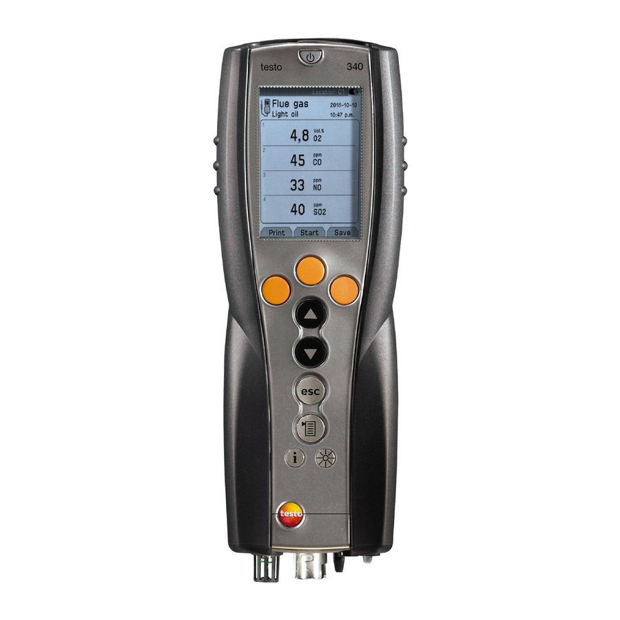
C. Product description C. Product description This chapter provides an overview of the individual components of the product. C.1 Measuring instrument C.1.1 Overview Infrared interface Placeholder: Do not point infrared beam at Pbersicht.tif people's eyes! Interfaces: USB, PS2 On/Off switch Condensate trap (on rear) Attachment for carrying strap (on rear) Magnetic holders (on rear) -
Page 11: Keypad
C. Product description 11 C.1.2 Keypad Functions Switch measuring instrument on/off Function key (orange, 3x), relevant function is shown on the display Scroll up, increase value Scroll down, reduce value Back, cancel function Open Main menu: press briefly (changed settigs are stored, measurement values are carried over into the menu Flue gas);... -
Page 12: Instrument Connections
C. Product description Settings view Active menu Function fields for entering commands Scroll bar Selection field for adjustable values: The selected value is shown with a grey background. Unavailable values are written in grey type. Function keys for entering commands Measuring view Active menu, depending on the selected function: Additional information (e.g. -
Page 13: Interfaces
C. Product description C.1.5 Interfaces USB interface: connection to PC PS2 interface: Adapter for automatic furnaces Ir/IrDA interface Bluetooth interface C.1.6 Components Rechargeable battery Measuring gas pump Sensor slot 1: O2 Sensor slot 2: CO, COlow, NO, NOlow, SO2 Sensor slot 3: NO, NOlow, NO2 Sensor slot 4: CO, COlow, SO2, NO2... -
Page 14: Carrying Strap
D. Commissioning C.1.7 Carrying strap To secure the carrying strap: 1 Place the measuring instrument on its front. Placeholder: 2 Attach carrying strap in the fixture ( Halterung_Verschluss- stopfen.tif Tragegurt.tif C.2 Modular flue gas probe Removable filter chamber with window and particle Placeholder: filter Abgassonde.tif... -
Page 15: Operation
Press the orange key and push in the direction of the arrow. 4 Remove the rechargeable battery and insert a new one. Use only Testo 0515 0100 rechargeable bat- teries! 5 Close the rechargeable battery compartment: Press the orange key and push against the direc- tion of the arrow until the rechargeable battery engages. -
Page 16: Charging Batteries
E. Operation E.1.2 Charging batteries The rechargeable battery can only be charged at an ambient temperature of ±0...+35°C. If the rechargeable battery has discharged completely, the charging time at room tempe- rature is approx. 5-6 hrs. Charging in the measuring instrument The measuring instrument must be switched off. -
Page 17: Probes/Sensors
E. Operation 17 E.2 Probes/sensors E.2.1 Connecting probes/sensors Sensor s s ocket: Sensor detection is carried out at the sensor socket during the activation process: Always connect the sensors you need to the measuring instrument before switching it on or switch the device on and then off again after a change of sensor so that the correct sensor data are read into the measuring instrument. -
Page 18: Replacing The Probe Module
E. Operation E.2.2 Replacing the probe module 1 Press the key on the top of the probe handle and remove the probe module. 2 Fit a new probe module and engage it in place. E.3 Regular care E.3.1 Condensate trap The fill level of the condensate trap can be read from the markings on the trap. -
Page 19: Checking/Replacing The Particle Filter
E. Operation 19 E.3.2 Checking/replacing the particle filter Checking the particle filter: Check the particle filter of the modular flue gas probe for contamination at regular intervals: Check visually by looking through the window of the filter chamber. Replace the filter if there are signs of contamination Replacing the particle filter: The filter chamber may contain condensate 1 Open the filter chamber by turning it gently... -
Page 20: Calling Up The Function
E. Operation E.4.2 Calling up the function Functions which cannot be selected because the required sensor/probe is not con- nected are shown in grey type. 1 Select function: - The selected function is shown with a grey background. 2 Confirm selection: - The selected function is opened. -
Page 21: Printing Data
E. Operation 21 3 Repeat steps 1 and 2 as required. 4 Save the input: OK Save input E.4.4 Printing data Data are printed out via the function key . The function is only available if a prin- Print tout is possible. If data are to be transferred to a protocol printer via the infrared or Bluetooth interface, the printer that is to be used must be activated, see Printer , p. -
Page 22: Memory
E. Operation E.5 Memory All readings are allocated to the location that is activated at the time and can be saved in the Flue gas menus. Unsaved readings are lost when the measuring instrument is swit- ched off. Folders and locations can be created (max. 100 folders, max. 10 locations per folder), edited and activated and measurement protocols can be printed. -
Page 23: Location
E. Operation 23 E.5.2 Location Creating a new location: A location is always created in a folder. 1 Select the folder New location 2 Select the Location name Change 3 Enter values OK Save input 4 Repeat steps 2 and 3 for the other criteria accordingly. OK Go to measurement OK To location Ordering the locations list:... -
Page 24: Protocols
E. Operation The parameters (ambient air temperature), (ambient air humidity) Temp./amb. Hum/amb. (ambient air dew point) influence calculation of the qA (Flue gas loss) Dew p./amb. and DP (Flue gas dew point temperature). The parameters should be set to the factory settings for all standard applications (Temp./amb.: 20.0 °C, Hum/amb.: 80.0 %, Dew p./amb.: 16.4 °C). -
Page 25: Extras Memory
E. Operation 25 Displaying/printing/deleting an individual protocol: 1 Select the folder Select a location Data - The saved protocols are displayed. Protocols of measurement programs are marked with a vertical line and the number of individual measurements (e.g. ), for more |245 than 999 measurements dots are used ( ). -
Page 26: Instrument Diagnosis
E. Operation E.6 Instrument diagnosis Important operating values and instrument data are displayed. A gas path check can be carried out. The status of the sensors and any device errors not yet rectified can be displayed. Calling up the function: Inst’... -
Page 27: Instrument Settings
F. Configuration 27 Instrument settings F.1.1 Display edit The parameters/units and the display representation (number of readings displayed per display page) can be set. Available parameters and units (may vary from one instrument to another): Display Parameter Units Display Parameter Units Δ... -
Page 28: Printer
F. Configuration Calling up the function: Inst’ settings Display edit Setting the display representation: Select 4 values on disp large 8 values on disp small Changing parameters and units: 1 Select the display position. Options: To insert a space: Space To delete a parameter: Select parameter Select unit... -
Page 29: Start Keys Edit
F. Configuration 29 F.1.3 Start keys edit The assignment of the function keys depends on the function that is selected. Only the function keys in the start screen (shown when the measuring instrument is switched on) can be assigned any function from the menu. -
Page 30: Communication
F. Configuration F.1.5 Communication Select interface IR/IrDA/ interface Bluetooth. Calling up the function: Inst’ settings Communication Set interface IR/IrDA / interfaceBluetooth: Select oder IrDA Bluetooth F.1.6 Date / Time The date and the time can be set. Calling up the function: Inst’... -
Page 31: Sensor Settings
Setting the NO2 addition (as long as no NO2 sensor is plugged in): NO2 addition Option: Reset N02 addition to default value: Deflt Set the value Change Schematic presentation of gas path testo 340: Dilution 2x: All measuring cell slots (option) Dilution 5x: measuring cell slot 2 CO, H2-comp. COlow, H2-comp. - Page 32 F. Configuration Setting sensor protection: To extend the measuring range and protect the sensors against overloads, you can set thresholds which, when exceeded, activate sensor protection. Thresholds for a variety of parameters can be set, depending on the sensors that are connected. For instruments without "Dilution of all sensors"...
- Page 33 F. Configuration 33 Display ppm/hour counter (active only when sensors with exchangeable filters are used): For those sensors which have an exchangeable chemical filter for neutralizing cross- gases, a ppm/hour counter is available. this applies to: CO, H2 comp. sensor (filter life approx. 170000 ppmh) NO sensor (filter life approx.
- Page 34 · Maximum overpressure of the test gas: 30 hPa (recommended: unpressurised via bypass) · Charge the test gas for at least 3 min Recommended test gas concentrations and compositions are given in Testo's field guide to test gases. Recalibration - Possibly:Gas zeroing (30 s).
-
Page 35: Fuels
Name Set the values Change 2 Select the coefficient Option: To reset the chosen coefficients to default values: Deflt Set the values Change OK Save input The calculation of the fuel factors is carried out via the testo easyEmission software. -
Page 36: Measuring
G. Measuring G. Measuring This chapter describes the measuring tasks that can be carried out with the product. Familiarity with the contents of the chapter Operation (see p. 15) is assumed. G.1 Preparing measurements G.1.1 Zeroing phases Measuring the ambient air temperature (AT) If no ambient air temperature sensor is connected, the temperature measured by the thermocouple of the flue gas probe during the zeroing phase is used as the ambient air temperature. -
Page 37: Using The Modular Flue Gas Probe
G. Measuring 37 G.1.2 Using the modular flue gas probe Checking the thermocouple The thermocouple of the flue gas probe must not lie against the probe cage. Check before use. Bend the thermocouple back if necessary. Aligning the flue gas probe The flue gas must be able to flow freely past the thermocouple. -
Page 38: Flue Gas, Flue Gas + M/S, Flue Gas + Dp2
G. Measuring G.2 Measurements G.2.1 Flue gas, Flue gas + m/s, Flue gas + Δp2 The flue gas menus are the central measurement menus in which - in addition to the readings measured with this function - the readings of all measurements carried out are displayed (if this is selected in the menu). -
Page 39: Program
G. Measuring 39 Measuring: 1 Start measuring: Start - The readings are displayed. Option: Interrupt measurement and rinse sensors: Continue measurement: 2 Stop measuring: Stop Options: To print readings: Print To save readings: Save - The readings from the flue gas measurement, as well as any readings taken over into the menu from other measurement functions are stored and/or prin- Flue Gas... -
Page 40: Draught
G. Measuring G.2.3 Draught function is only available when a flue gas probe is connected. Draught Do not measure for longer than 5 min, as the drift of the pressure sensor means that the readings could be outside the tolerance limits. Calling up the function: Measurements Draught... -
Page 41: Gas Flow Rate
G. Measuring 41 Recording smoke tester no. / smoke numbers / oil derivative with the smoke tester testo 308 and wireless transfer: - t308 must be in Data Mode ( 1 Press function key t308 - The values recorded by the smoke tester are transferred. -
Page 42: Oil Flow Rate
G. Measuring G.2.6 Oil flow rate function is only available if the activated fuel is an oil. Oil flow rate Calling up the function: Measurements Oil flow rate Measuring: 1 Enter the flow rate: Enter the value Flowrate Change 2 Enter the oil pressure: Enter the value Change Oil pressure... -
Page 43: Dp2
G. Measuring 43 G.2.8 Δp2 Do not measure for longer than 5 min, as the drift of the pressure sensor means that the readings could be outside the tolerance limits. When measuring the gas flow pressure of gas heaters: Dangerous mixture of gases Danger o o f e e xplosion! Make sure there are no leaks between the sampling point and the measuring instrument. - Page 44 G. Measuring - The data are read from the automatic furnace. An update of the data takes place every 30s at the latest, this is dependent on the automatic furnace. Reading out current status data: The current data are displayed when a connection to the automatic furnace exists. The following data are displayed with the help of symbols: Component Status ON...
-
Page 45: Transferring Data
H. Transferring data H.1 Protocol printer If data are to be transferred to a Testo protocol printer via the infrared or Bluetooth inter- face, the printer that is to be used must be activated, see Printer , p. 28. Data are printed out via the function key . -
Page 46: Care And Maintenance
I. Care and maintanance Care and maintenance This chapter describes the steps and action required in order to keep the product func- tioning properly. See also Regular care , p. 18. Cleaning the measuring instrument If the housing of the instrument is dirty, clean it with a damp cloth. Do not use any aggressive cleaning agents or solvents. -
Page 47: Filter For Co, H2-Comp., No Exchanging Sensors
I. Care and maintanance 47 After replacing an O2 sensor, wait 60 min before using the instrument again. If retrofitting a sensor you must activate the relevant measuring parameter and unit, see Display edit , p. 27. Filter for CO, H2-comp., NO exchanging sensors The measuring instrument must be switched off and the mains unit disconnected from the mains supply. -
Page 48: Cleaning The Modular Flue Gas Probe
I. Care and maintenance Cleaning the modular flue gas probe Detach the flue gas probe from the measuring instrument before cleaning. 1 Release the probe catch by pressing the key on the probe handle and remove the probe module. Probe shafts with preliminary filter: Unscrew the preliminary filter. -
Page 49: Questions And Answers
· Printer is out of wireless range. Place printer within wireless range. If we could not answer your question, please contact your dealer or Testo Customer Service. For contact data, see back of this document or web page www.testo.com/ser- vice-contact... -
Page 50: Technical Data
K. Technical data K. Technical data K.1 Standards and tests · As declared in the certificate of conformity, this product complies with Directive 2004/108/EEC. · This product is TÜV approved to EN 50379 part 2, exception: SO2 and NO2 parame- ters are not tested, recalibration is not blocked. - Page 51 K. Technical data 51 Parameter Measuring range Accuracy Resolution Pabs 600...1150hPa ±10hPa 1hPa Temperature (NiCrNi) -40...1200°C ±0.5°C at 0.0...99°C 0.1°C at -40.0...999.9°C depends ±0.5% of reading in rest of range 0.1°C at 1000°C...1200°C on probe Efficiency 0...120% 0.1% Flue gas loss 0...99,9% 0,1% Flue gas dewpoint 0...99,9°C...
-
Page 52: Other Instrument Data
IP 40 Guarantee Measuring instrument: 24 months Sensors: 12 months, O2 sensor: 18 months Flue gas probe: 24 months Thermocouple: 12 months Battery: 12 months Warranty conditions: see www.testo.com/warranty Option Bluetooth Typ-designation: BlueNiceCom IV ® Bluetooth Qualified Product Notice: BNC4_HW2x_SW2xx... -
Page 53: Ec Declaration Of Conformity
K. Technical data 53 K.4 EC declaration of conformity... -
Page 54: Principles Of Calculation
K. Technical data K.5 Principles of calculation K.5.1 Fuel parameters Fuel 2 max 2 ref Natural Gas 11,90 3,00% 0,35% 0,39 40,00 24,4 53,42 48,16 Light Oil 15,50 3,00% 0,48% 0,51 53,00 45,6 42,8 Heavy Oil 15,80 3,00% 0,51% 0,51 54,00 11,5 42,9... - Page 55 K. Technical data 55 P P o o i i s s o o n n i i n n d d e e x x : : ratio = Measured carbon monoxide x 10000 value in % Calculated carbon dioxide value E E x x c c e e s s s s A A i i r r ( ( E E x x A A i i r r ) ) : : 21%:...
- Page 56 K. Technical data Mass flow: M M a a s s s s f f l l o o w w C C O O : : MCO = CO [kg/h] [ppm] x F x 1.25 [kg/m ] x Z M M a a s s s s f f l l o o w w N N O O = NO [kg/h] [ppm] x F...
-
Page 57: Recommended Rinsing Times
K. Technical data 57 K.6 Recommended rinsing times Recommended rinsing times in measurements with high concentrations and longer measurements: Rinse instrument: Expose probe to fresh air and start flue gas analysis Parameter Concentration [ppm] Measurement duration [min] Recommended rinsing time [min] 1000 2000 4000... -
Page 58: Accessories/Spare Parts
L. Accesssories/spare parts L. Accessories/spare parts Designation Article no. Modular flue gas probes Modular flue gas probe 335mm, 500°C, thermocouple 0.8mm 0600 9766 Modular flue gas probe 700mm, 500°C, thermocouple 0.8mm 0600 9767 Modular flue gas probe 335mm, 1000°C, thermocouple 0.8mm 0600 8764 Modular flue gas probe 700mm, 1000°C, thermocouple 0.8mm 0600 8765... - Page 59 CO-, H2-comp. sensor 0554 4100 NO sensor 0554 4150 Other retrofiting kits Bluetooth only retrofittable by Testo service Dilution of all sensors only retrofittable by Testo service Other accessories Infrared printer 0554 0549 Bluetooth printer incl. rechargeable battery and charging adapter...
-
Page 60: Functional Overview
Functional overview Functional overview The table gives an overview of the most important functions configured on the individual instruments. Detailed information about the individual functions can be found on the pages indicated. Task Call/function see page Measurements Flue gas measurement Flue gas Flue gas measurement with parallel flow measurement Flue gas + m/s... - Page 61 Functional overview 61 Task Call/function see page Memory Extra Print all protocols in the memory Print all data Delete all protocols in the memory Delete all data Delete memory Clear whole memory (protocols and locations) Inst’ settings Set reading display Display edit Printer Select printer, set print text...
- Page 64 0970 3401 en 01 V01.00 en_GB...
- Page 65 Thank you for reading this data sheet. For pricing or for further information, please contact us at our UK Office, using the details below. UK Office Keison Products, P.O. Box 2124, Chelmsford, Essex, CM1 3UP, England. Tel: +44 (0)330 088 0560 Fax: +44 (0)1245 808399 Email: sales@keison.co.uk...
Need help?
Do you have a question about the 340 and is the answer not in the manual?
Questions and answers