ETC F-Drive R12 Series Installation Manual
Hide thumbs
Also See for F-Drive R12 Series:
- Installation manual (56 pages) ,
- Reference manual (17 pages) ,
- Reference manual (8 pages)

Subscribe to Our Youtube Channel
Related Manuals for ETC F-Drive R12 Series


Summary of Contents for ETC F-Drive R12 Series
- Page 1 F-Drive Series R12 Installation Manual Part Number: 7148M2100 Rev: E Released: 2022-01...
- Page 2 To view a list of ETC trademarks and patents, go to etcconnect.com/ip. All other trademarks, both marked and not marked, are the property of their respective owners. ETC intends this document, whether printed or electronic, to be provided in its entirety.
-
Page 3: Table Of Contents
Table of Contents Introduction System Components F-Drive System Design Tool Compatible Products LED Dimming Compatibility Database Documentation for Compatible Products Document Conventions Help from ETC Technical Services Safety IMPORTANT SAFEGUARDS Label Symbols Chapter 1 Overview Features Output Cards CC-150 Card FTW-150 Card Chroma Card CV-150 Card ArcLamp 150 Card... - Page 4 Connect Ground/Earth Wire the DC Power Output Final Installation Steps Bussing Kit Parts Illustration Chapter 5 Install the R12 Rack-Mount the R12 Connect the DC Power Input DMX In and Thru Connections DMX Cat5 Preparation and Termination DMX Cable Preparation and Termination Terminate DMX In and Thru Panic R12 Output Cards Finish Installation...
- Page 5 Chapter 8 Power Up and Control Power Up Procedure Identify DMX System Control ArcSystem Navis Luminaire DMX Personalities On Below Minimum RDM Parameters Live Edit Configuration Files Edit Offline and Save Configuration Files to MicroSD 39 Firmware Upgrade Instructions MicroSD Firmware Upgrade Instructions Maintenance Troubleshooting F-Drive R12 Control Card LED Indicators...
- Page 6 R12 Installation Manual...
-
Page 7: Introduction
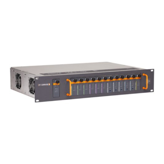
Introduction Congratulations on your purchase of the ETC F-Drive Series R12. The F-Drive Series R12 LED power control solution provides a modular, centralized approach for controlling LED luminaires. The R12 is a card cage enclosure that can hold up to 12 low-voltage output cards, providing power and data to multiple circuits per card. -
Page 8: Documentation For Compatible Products
RISK OF ELECTRIC SHOCK! This warning statement indicates situations where there is a risk of electric shock. All ETC documents are available for free download from our website: etcconnect.com. Please email comments about this manual to: TechComm@etcconnect.com. R12 Installation Manual... -
Page 9: Help From Etc Technical Services
Help from ETC Technical Services If you are having difficulties and your problem is not addressed by this document, try the ETC support website at support.etcconnect.com or the main ETC website at etcconnect.com. If none of these resources are sufficient, contact ETC Technical Services directly at one of the offices identified below. -
Page 10: Safety
Safety The F-Drive Series R12 is intended for professional use only. Read the entire manual before using this equipment. IMPORTANT SAFEGUARDS When using electrical equipment, basic safety precautions should always be followed including the following: READ AND FOLLOW ALL SAFETY • INSTRUCTIONS. -
Page 11: Overview
Chapter 1 Overview F-Drive R12 Driver Features Compatible with a wide range of control systems • Compact size: fits EU or US 19-inch rack, 2U height, 12.8 inch depth • Requires 48 VDC input from an external power supply, recommended minimum 1500 W • Holds up to 12 low-voltage output cards for remote control of up to 48 circuits •... -
Page 12: Cc-150 Card
If your load is not in the compatibility database, follow the instructions at the link above to contact the ETC Applications Engineering department to arrange for compatibility testing. adjustable 200–700 mA constant current per channel, default output 600 mA (see Configure the CC-150 Card on page 29... -
Page 13: Ftw-150 Card
FTW-150 Card The FTW-150 Card is designed for use with Navis Fade to Warm luminaires. constant current, maximum 450 mA per channel Output 1.8 A total per card 48 VDC Output Channels four channels on a single RJ45 or eight-pin terminal block Loads up to four Navis 100 Fade to Warm luminaires per card Maximum Load 21.6 W per channel, 86 W per card Model Number... -
Page 14: Cv-150 Card
If your load is not in the compatibility database, follow the instructions at the link above to contact the ETC Applications Engineering department to arrange for compatibility testing. adjustable 24–28 VDC constant voltage Output 2.1 A per channel, 6.25 A total per card... -
Page 15: Before You Begin Installation
Before You Begin Installation Review the following information before installing the F-Drive R12. Installation Requirements Ambient operating temperature 0–40°C (32–104°F), 5–95% non-condensing humidity. • Dry locations only. • The R12 requires a 19-inch equipment rack that must support the weight of an R12 frame, •... - Page 16 Voltage Drop Voltage drop along load wiring is a consideration for constant voltage loads. Voltage drop calculations vary by project and are based on the type, length, and gauge of wire. The CV-150 Card and the ArcLamp 150 Card have an adjustable dial on the front of the output card to set the 24–28 VDC (+/-5%) output.
-
Page 17: Prepare To Install The R12
2. Inspect the order for completeness. Check the box contents received against the packing list to ensure that your order is • complete. If you discover a problem with the contents of the shipment, contact ETC. See Help from • ETC Technical Services on page 3 R12 ships with the control card (ETC part number 7148K1000) installed and with blanks covering... -
Page 18: Output Card Wire And Terminal Specifications
Output Card Wire and Terminal Specifications Strip Torque Output Card Terminal/Connector Wire Range/Specifcation Length Rating You must use 0.25 mm Chroma Card RJ45 connector for (23 AWG) or larger Terminate to T568B FTW-150 Card output power or conductors in Category- standard. CC-150 Card power/data type cable. 0.2–1.5 mm FTW-150 Card eight-pin connector... -
Page 19: Install 48 Vdc Power Supplies
Chapter 3 Install 48 VDC Power Supplies The MEAN WELL RKP-1UI rack-mount units are 1U, low-profile power distribution solutions perfectly suited for providing 48 VDC power to the ETC F-Drive R12. The MEAN WELL rack-mount unit should only be installed by a qualified electrician or service technician. -
Page 20: Mean Well Rkp-1Ui Features
MEAN WELL. Three RCP-2000 power supply modules provide up to 6000 W to a single RKP-1UI rack- • mount unit. Bussing kits are available from ETC to bus together up to three rack systems. See Bussing • Kits on page 17 Three bussed RKP-1UI rack-mount units bussed together and containing nine RCP-2000 •... -
Page 21: Install The Power Supply In The Rack
Connect Ground/Earth Each RKP-1UI three-bay frame has a ground/earth stud for connection to the equipment rack ground/earth. ETC provides a 0.6 m (2 ft) harness of 8 AWG insulated wire with a ring terminal Bussing on one end and a bare end on the other with the R12 bussing kits for this purpose. See Kits on page 17... -
Page 22: Wire The Dc Power Output
Wire the DC Power Output The box for each F-Drive R12 includes a red-and-black DC power wiring harness with an F-Drive R12 power input plug on one end and bare ends on the other. You also need a bussing kit with Bussing Kits on the facing page tin-plated bus bars. -
Page 23: Final Installation Steps
Bussing Kits ETC offers bussing kits for installations with one, two, or three RKP-1UI rack-mount units. The following bussing kits are available: Bussing Kit Contents Number of Bussing Kit Number Number Number Bussing Kit RKP-1U Number Number and Size Model... -
Page 24: Bussing Kit Parts Illustration
Bussing Kit Parts Illustration Screws provided with the MEAN WELL three-bay frame 1U bus bar DC output terminal on MEAN WELL three-bay frame Threaded standoff 2U bus bar 3U bus bar 2U bus bar kit RJ45 termination 3U bus bar kit RJ45 termination RJ45 bussing cable (only included in 2U or 3U bussing kits) Install RJ45 terminators provided by MEAN WELL in these... -
Page 25: Install The R12
Chapter 5 Install the R12 RJ45 power and data outputs, one per output card (A–L) eight-pin terminal power outputs, one per output card (A1–A4 through L1–L4) breaker power input from external 48 VDC supply Panic switches (see Panic Connector on page 31 Panic Connector on page 31 three-pin Panic connector (see DMX In... -
Page 26: Dmx In And Thru Connections
DMX In and Thru Connections DMX In and DMX Thru cables terminate to three-pin IDC or screw-terminal connectors.The F-Drive R12 includes a DMX termination kit (ETC part number 4268K1004) provides both screw terminal connectors for use with Belden 9729 cable and IDC connectors for use with Cat5 cable. -
Page 27: Dmx Cable Preparation And Termination
2. Strip 18 cm (7 in) off the outer jacket. 3. Label the cable with the data type and run designation. (DMX1, DMX2, etc.) 4. Strip the foil shielding from each wire set to within 6 mm (1/4 in) of the outer jacket. -
Page 28: Panic
Panic For information on wiring the Panic input and configuring the Panic switches, see Panic Connector on page 31 R12 Output Cards Install the required output cards. See Install R12 Output Cards on page 23 Finish Installation 1. Apply power to the unit. 2. -
Page 29: Install R12 Output Cards
Chapter 6 Install R12 Output Cards Control card Output cards F-Drive R12 output cards and the control card can be installed and replaced while the R12 is powered on. WARNING: RISK OF ELECTRIC SHOCK! Working inside the F-Drive with power applied exposes you to the possibility of dangerous currents and voltages. -
Page 30: Chroma Card Dmx Footprint
1. Using a Phillips screwdriver, remove the screw securing the plate that covers the output card slot. Leave plates in place over empty output card slots until you are ready to install an output • card. Save any plates and screws that you remove and install them over empty card slots as •... -
Page 31: Navis 100 Luminaires
Navis 100 Luminaires See the Navis 100 Installation Guide for luminaire installation instructions and compatibility with F-DriveR12 output cards. ETC documents are available for download in PDF format free of charge at etcconnect.com. Navis 100 luminaires can be directly connected to their compatible output card via Category- type cable in a daisy chain. - Page 32 (23 AWG) or larger conductors. Connect up to four luminaires per output card. The F-Drive R12 ships with twelve eight-pin connectors (ETC part number 7148K1016). Follow these instructions to prepare one cable per luminaire with an RJ45 plug on one end, wired to two pins of the eight-pin screw-terminal connector on the other end.
-
Page 33: Arcsystem Pro One-Cell Luminaires
Wire the Eight-Pin Connector 1. Terminate the luminaire end of the cable according to T568B standard. 2. On the end of the cable going to the equipment rack, follow installation procedures for the Category-type cable that you are using and strip the ends of the wires. 3. -
Page 34: Third-Party Fixtures
If your load is not in the compatibility database, follow the instructions at the link above to contact the ETC Applications Engineering department to arrange for compatibility testing. Third-Party constant current or constant voltage fixtures can be connected to a CC-150 Card or CV-150 Card either directly to the eight-pin terminal block on the output card or to the RJ45... -
Page 35: Arclamps
ArcLamps ArcLamp is an LED source from ETC that is available in several models including the choice of screw base, color temperature, and clear or frosted glass finish. ArcLamp systems require a ArcLamp 150 Card in order to be powered and controlled by the F-Drive R12. The ArcLamp 150 Card supports a total of thirty-two 4.4 W ArcLamps with up to eight ArcLamps per... -
Page 36: Record Installed Output Cards
Record Installed Output Cards Use this page to record the location of output cards in your F-Drive R12. Make additional copies as necessary for each R12. The card slot labels run A–L from left to right when facing the front of the R12, and A–L from right to left when facing the back. -
Page 37: Panic Connector
Chapter 7 Panic Connector The R12 supports emergency lighting control bypass in the following ways: It accepts input from non-isolated (dry) contact closure powered by the F-Drive R12. • It accepts input from isolated (wet) contact closure providing +48 VDC. •... -
Page 38: Wire The Panic Connector
Wire the Panic Connector A three-pin header with a pluggable connector is provided for panic connections (ETC part number 7148K1015). Follow the directions below according to the type of contact you are using. Non-Isolated (Dry) Contact 1. Strip 6 mm (1/4 in) of insulation from the two panic wires. -
Page 39: How To Use R12 With A W1 Emergency Driver
How to Use R12 with a W1 Emergency Driver The R12 panic connector can be connected to the input of a W1 Emergency Driver to trigger the emergency functionality of the W1 Emergency Driver in the event of power loss to the R12. The R12 "COM" and "+48V" terminals are wired to the W1 Emergency Driver Sense Input terminals. -
Page 40: Power Up And Control
RDM Parameters on page 36 DMX System Control You can control the R12 over wired DMX from a lighting console or ETC Concert software. Concert is available for free download at etcconnect.com/Concert. F-Drive Series products are compliant with DMX 512-A (ANSI E1.11-2008 (R2013)). -
Page 41: Arcsystem Navis Luminaire Dmx Personalities
ArcSystem Navis Luminaire DMX Personalities ArcSystem Navis RGBW luminaires have two personality options: direct (IRGBW) and IRGB. ArcSystem Navis Fade to Warm luminaires have two personality options: Intensity and Warm Trim. ArcSystem Navis Fixed White luminaires have a single personality: Intensity. The personality is set per output card. The IRGB DMX personality provides a means for matching the output from ArcSystem Navis RGBW luminaires to 3000 K Fixed White and Fade to Warm luminaires. -
Page 42: Rdm Parameters
0x0080 ASCII string for model description FTW-150 Card: "FTW-150" CV-150 Card: "CV-150 ArcLamp 150 Card: "ArcLamp-150" CC-150 Card: "CC-150" Manufacturer Label 0x0081 ASCII string for manufacturer label Get returns "ETC"from the root (control card) only. Get or Set root device (control card): "F-Drive R12" Device Label 0x0082 ASCII string for device label • subdevices (output cards) : "[channel] %d" where •... - Page 43 Parameter RDM PID Value Notes Personalities Default Supported Output Cards Personality 1= Intensity ✓ ✓ 2 = Direct (IRGBW) Chroma Card DMX Personality 0x00E0 ✓ ✓ 1 3 = IRGB FTW-150 Card ArcLamp 150 Card, 4 = Warm Trim ✓ CC-150 Card, and CV-150 Card DMX Personality Description 0x00E1 DMX Start Address 0x00F0 Range = 001 to 512 Sending "set" to root (control card) will set the start...
- Page 44 Parameter RDM PID Value Notes ASCII text string. FTW Temperature Scaling 0x8052 The structure of data includes: This parameter is used to set or get the fade to warm temperature scaling on a FTW-150 Card. This feature enabled (unin8_t): 0 = disabled, • allows you to set a maximum color temperature 1 = enabled Max CT (unint16_t): 2700K–...
-
Page 45: Live Edit Configuration Files
Live Edit Configuration Files You can live edit configuration files using ETC Concert software v4.1.2 or later with the F-Drive device package. Concert is available for free download at etcconnect.com/Concert. For more information on Concert, see the help files within the Concert application. -
Page 46: Firmware Upgrade Instructions
When commissioning a system installation, check all F-Drive Series drivers to ensure that the latest firmware is present. If the firmware is not up to date, upgrade it using ETC Concert and ETC UpdaterAtor software before commissioning is completed. For more information on UpdaterAtor, download the UpdaterAtor Software Quick Guide for free from etcconnect.com. -
Page 47: Maintenance
Maintenance WARNING: RISK OF DEATH BY ELECTRIC SHOCK! Failure to disconnect all power to the system before installation, maintenance, cleaning, or any other system modification could result in serious injury or death. AVERTISSEMENT : RISQUE DE MORT PAR DÉCHARGE ÉLECTRIQUE! Négliger de débrancher toutes les sources d’alimentation du système avant l’installation, l’entretien, le nettoyage ou toute autre modification du système peut causer des blessures graves ou la mort. -
Page 48: Troubleshooting
Troubleshooting F-Drive R12 Control Card LED Indicators Note: If you set the RDM Identify parameter for the control card to 1 for "start identify," it will cause all LEDs on the control card to blink in a 500 ms on, 500 ms off pattern until the Identify parameter is set to stop. -
Page 49: F-Drive R12 Output Card Led Indicators
Red "Error" LED Behavior Status or Error Normal operation. Solid There is an active error. See Errors on the next page Fast Invalid RDM ID. The "Power" (blue) and "Link" (yellow) LEDs will also slow Blink blink. Double SD card error. Blink Triple Firmware download is in progress. -
Page 50: Errors
Errors An illuminated red "Error" LED on a control card or an illuminated red LED on a channel of an output card can be the result of several problems, depending on the type of card. The errors below are also reported through RDM Status Messages. See RDM Parameters on page 36 Output Card... -
Page 51: Appendix A Compliance
Appendix A Compliance For current and complete compliance information, view the product datasheets at etcconnect.com/Products/Power-Controls/LED-Drivers/F-Drive/Documentation.aspx. For complete product documentation, including compliance documentation, visit etcconnect.com. FCC Compliance F-Drive R12 (For any FCC matters): Electronic Theatre Controls, Inc. 3031 Pleasant View Road Middleton, WI 53562 +1 (608) 831-4116 etcconnect.com... - Page 52 New York, NY | Orlando, FL | Los Angeles, CA | Austin, TX etcconnect.com | Support support.etcconnect.com | Contact etcconnect.com/contactETC © 2022 ETC | Trademark and patent info: etcconnect.com/ip Product information and specifications subject to change. ETC intends this document to be provided in its entirety. 7148M2100 Rev E Released 2022-01...
Need help?
Do you have a question about the F-Drive R12 Series and is the answer not in the manual?
Questions and answers