Table of Contents
Advertisement
Quick Links
CP-2500
Control Panel
For ADS-B UAT Device
9080-17250-( )
Installation Manual
This manual contains installation instructions,
recommended flightline maintenance information,
and operation information for the CP-2500 Control
Panel. This information is supplemented and kept
current by revisions, service letters, and service
bulletins.
0040-17251-01 (Revision D)
March 15, 2018
Advertisement
Table of Contents

Subscribe to Our Youtube Channel
Summary of Contents for L3 CP-2500
- Page 1 For ADS-B UAT Device 9080-17250-( ) Installation Manual This manual contains installation instructions, recommended flightline maintenance information, and operation information for the CP-2500 Control Panel. This information is supplemented and kept current by revisions, service letters, and service bulletins. 0040-17251-01 (Revision D)
-
Page 2: Foreword
Foreword This manual provides information intended for use by persons who, in accordance with current regulatory requirements, are qualified to install this equipment. Installation requirements may vary, depending on the particularities of each aircraft, and this manual is intended as a guideline for that purpose. If further information is required, please contact: Aviation Communications and Surveillance Systems 19810 N. -
Page 3: About This Manual
CP-2500 Installation Manual ABOUT THIS MANUAL SECTION 1 – GENERAL INFORMATION This section includes equipment specifications, functional description, a list of items furnished and items required but not supplied with the equipment. SECTION 2 - INSTALLATION This section contains instructions for unpacking the equipment and inspection for in-shipment damage. -
Page 4: References
Contact Customer Service [1-800-453-0288] to determine availability of technical publications and directives. Service literature and publications can be obtained by either downloading from the L3 Technical Publications website (may require secure site access) or by receiving a copy via email. Send an email request to a vionics.techpubs@L3T.com... - Page 5 CP-2500 Installation Manual List of Effective Pages Revision History: Revision A ....December 16, 2014 Revision B ....December 15, 2015 Revision C ....July 19, 2017 Revision D ....March 15, 2018 Section Titles and the total number of pages in this publication consists of the following:...
-
Page 6: Table Of Contents
CP-2500 Installation Manual Table of Contents Paragraph Page Foreword ............................... 2 About This Manual ............................i References ..............................ii List of Effective Pages ........................... iii Table of Contents ............................iv List of Illustrations ............................vi List of Tables ..............................vi Acronyms, Symbols, and Abbreviations ...................... -
Page 7: Table Of Contents
CP-2500 Installation Manual Table of Contents (cont.) Paragraph Page Section 3 Installation Checkout Introduction............................3-1 Operation............................3-1 Installation Checkout ......................... 3-2 3.3.1 Power On Self Test ........................3-2 3.3.2 Display Check ..........................3-2 3.3.3 Activate Maintenance Self Test ..................... 3-6 3.3.4... - Page 8 Figure 2-4: (P1) Mating Connector and Pin Assignments ................. 2-6 Figure 2-5: Interconnect Wiring Diagram for NGT-1000/-2000/-2500 ............2-7 Figure 2-6: Interconnect Wiring Diagram for Lynx NGT-9000R ..............2-8 Figure 3-1: CP-2500 Display and Controls ....................3-2 List of Tables Table Page Table 1-1: CP-2500 Configurations ......................
-
Page 9: Acronyms, Symbols, And Abbreviations
CP-2500 Installation Manual Acronyms, Symbols, and Abbreviations Symbol or Acronym Definition Advisory Circular ADS-B Automatic Dependent Surveillance-Broadcast Altitude Airplane Flight Manual Aircraft Maintenance Manual Aviation Products Sector ARINC Aeronautical Radio, Incorporated Air Traffic Control ATCRBS Air Traffic Control Radar Beacon System... - Page 10 CP-2500 Installation Manual This page intentionally blank Page viii 0040-17251-01 March 15, 2018 Revision D...
-
Page 11: General Information
General Information 1.1 INTRODUCTION This section includes functional description and equipment specifications for the CP-2500 Control Panel. Included at the end of this section is a list of equipment required but not supplied. Refer to Table 1-1 for a list of available CP-2500 configurations. -
Page 12: Functional Description
Installation Manual 1.2 FUNCTIONAL DESCRIPTION The CP-2500 is an ADS-B Control Panel that interfaces with the Lynx® MultiLink Surveillance System via a standard RS-232 interface. All connections to the Control Panel are made through a single 15 pin male connector. The panel features three buttons and a dual concentric knob that can be rotated and pressed to activate functions. -
Page 13: Ngt-1000/-2000/-2500
• Set Flight ID (optional - enabled during installation) • Activate Anonymous Mode (optional - enabled during installation) • Activation of Self-Test The CP-2500 receives and displays the following information. • Transponder Code Mismatch Message • Fault Indications • Fault Messages •... -
Page 14: Specifications
See outline drawings in installation section. SIZE: WEIGHT: 0.5 lbs (0.23 kg) CHASSIS GROUND: Bonding impedance between aircraft ground and the CP-2500 Chassis must be less than 2.5 milliohms. POWER REQUIREMENTS: + 11.0 to 33.0 Volts DC, 4 Watts Max Startup. 2 Watts Nominal. -
Page 15: Modifications
CP-2500 Installation Manual 1.4 MODIFICATIONS Modification (MOD) for the CP-2500 is identified by an entry on the S/N & ID tag on individual units. Table 1-2: Hardware Modifications MOD # EFFECTIVITY / COMPLIANCE DESCRIPTION None 1.5 CONFIGURATON VERSIONS Configuration version for the CP-2500 is shown on the display during startup. -
Page 16: Installation Kit
The article may be installed only if further evaluation by the applicant documents an acceptable installation and is approved by the Administrator. • ® The CP-2500 may only be installed with an approved Lynx MultiLink Surveillance System. Page 1-6 General Information 0040-17251-01... -
Page 17: Installation
2.2.1 Transport and Storage Considerations Transport of the CP-2500 should be done in accordance with standard procedures, i.e. hand carried or transported in the original container. Storage of the CP-2500 must be consistent with industry standards for avionics equipment and will perform satisfactorily after periods of storage up to 18 months. -
Page 18: Location
2.3.1 Location The CP-2500 should be mounted in the instrument panel slightly below and in close proximity with the pilot's normal line of view, with the controls within easy reach. In selecting a location, consider the... -
Page 19: Figure 2-2: Outline Dimensions For 9080-17250-01 & -02
CP-2500 Installation Manual Figure 2-2: Outline Dimensions for 9080-17250-01 & -02 0040-17251-01 Installation Page 2-3 Revision D March 15, 2018... -
Page 20: Figure 2-3: Outline Dimensions For 9080-17250-12
CP-2500 Installation Manual Figure 2-3: Outline Dimensions for 9080-17250-12 Page 2-4 Installation 0040-17251-01 March 15, 2018 Revision D... -
Page 21: Electrical Connections
Installer is responsible for determining appropriate circuit breakers needed to protect aircraft wiring. Manufacturer recommends a 1.0 amp circuit breaker. The CP-2500 can alternately share a circuit breaker with the Lynx MSS. Refer to the installation manual for the Lynx MSS for details (refer to references in front section for manual part numbers). -
Page 22: Figure 2-4: (P1) Mating Connector And Pin Assignments
CP-2500 Installation Manual Figure 2-4: (P1) Mating Connector and Pin Assignments Page 2-6 Installation 0040-17251-01 March 15, 2018 Revision D... -
Page 23: Figure 2-5: Interconnect Wiring Diagram For Ngt-1000/-2000/-2500
CP-2500 Installation Manual Figure 2-5: Interconnect Wiring Diagram for NGT-1000/-2000/-2500 0040-17251-01 Installation Page 2-7 Revision D March 15, 2018... -
Page 24: Figure 2-6: Interconnect Wiring Diagram For Lynx Ngt-9000R
CP-2500 Installation Manual Figure 2-6: Interconnect Wiring Diagram for Lynx NGT-9000R Page 2-8 Installation 0040-17251-01 March 15, 2018 Revision D... -
Page 25: Installation
CP-2500 into the instrument panel. The connection of mating connector may be required before installation of the unit. 2. The CP-2500 mounts on the backside of the instrument panel. Carefully hold the CP-2500 in place behind the instrument panel. - Page 26 CP-2500 Installation Manual This page intentionally blank Page 2-10 Installation 0040-17251-01 March 15, 2018 Revision D...
-
Page 27: Installation Checkout 3.1 Introduction
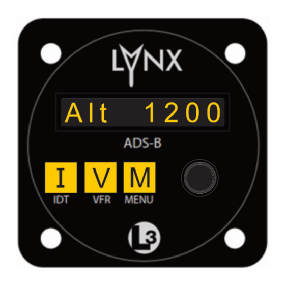
Lynx MSS. The display of the CP-2500 shows the operational mode on the left side of the display and the squawk code on the right side of the display as shown in Figure 3-1. -
Page 28: Installation Checkout
(Note - FW and HW versions are listed in the General Information section) • If a “Failed” message is shown on the display, cycle power the CP-2500. If the “Failed” message continues, replacement of the CP-2500 may be required. Contact ACSS Field Service before removal of the unit. - Page 29 NO LRU RESPONSE (incorporated in CP-2500 Firmware 15 and later) • GPS FAIL • ADS-B SYSTEM FAIL The following messages may be seen, but do not indicate a problem with the CP-2500 or the Lynx MSS. • GPS INIT: This message is removed after the GPS completes initialization. •...
- Page 30 ADS-B SYSTEM FAIL • TAS FAIL (Software 1.2 only) The following messages may be seen, but do not indicate a problem with the CP-2500 or the Lynx MSS. • GPS INIT: This message is removed after the GPS completes initialization.
- Page 31 TAS FAIL • TCAS FAIL • TAWS FAIL The following messages may be seen, but do not indicate a problem with the CP-2500 or the Lynx MSS. • GPS INIT: This message is removed after the GPS completes initialization. •...
-
Page 32: Activate Maintenance Self Test
CP-2500 Installation Manual 3.3.3 Activate Maintenance Self Test Perform the following self-test based on the Lynx MSS interface. A failure indicates a problem with the interface to the Lynx MSS or that a problem exists with the Lynx MSS or one of the system components. - Page 33 The results can be “Passed”, “Failed”, or “No LRU Response”. The result is shown for 10 seconds. • If a failed message is seen, a series of one or more fail messages are shown on the CP-2500 screen for 5 seconds each. The possible fail messages are GPS Fail, ADS-B IN Fail, ADS-B OUT Fail, and FIS-B Fail (NGT-2000/-2500 only).
- Page 34 “ADS-B IN FAIL”, “FIS-B FAIL”, “GPS FAIL”, “TAS FAIL”, “TAWS FAIL”. • If a degraded condition is detected a degraded message is flashed on the CP-2500 screen for 5 seconds. The possible degraded messages are “GPS INIT”, “ADS-B OUT DEGRADED”, “ADS-B IN DEGRADED”, “TAS DEGRADED”, “CONFIG MODULE - SERVICE SOON”.
-
Page 35: Check Brightness Controls
FAIL”, “FIS-B FAIL”, “GPS FAIL”, “TAS FAIL”, “TCAS FAIL”, “TAWS FAIL”. • If a degraded condition is detected a degraded message is flashed on the CP-2500 screen for 5 seconds. The possible degraded messages are “GPS INIT”, “ADS-B OUT DEGRADED”, “ADS-B IN DEGRADED”, “TAS DEGRADED”, “TCAS DEGRADED”,... - Page 36 CP-2500 Installation Manual This page intentionally blank Page 3-10 Installation Checkout 0040-17251-01 March 15, 2018 Revision D...
-
Page 37: Maintenance
4.3 FAULT ISOLATION Most problems associated with the CP-2500 causes the unit to fail the built-in test and can be checked by running a Maintenance Self Test. Information available from these tests can help identify conditions that need to be resolved. -
Page 38: Remove And Replace Procedures
CP-2500 Installation Manual 4.4.1 Remove and Replace Procedures Use this procedure to remove and replace the CP-2500. The instructions herein are generic in scope, specific instructions can be found in the Aircraft Maintenance Manual (AMM), if applicable. Removal Procedure Remove (4) mounting screws securing the control panel to the instrument panel. -
Page 39: Signal Name & Cable Characteristics
A.1 INTRODUCTION This appendix defines Digital Interface Label information and electrical characteristics of input and output signals to the CP-2500 Control Panel. Sufficient data is included to perform an electrical load analysis for the aircraft. Connection information identifies the connector-pin and signal names as they appear on the external interconnect wiring diagram shown in the installation section. -
Page 40: Wire And Signal Characteristics For The J1 Connector
CP-2500 Installation Manual A.2 WIRE AND SIGNAL CHARACTERISTICS FOR THE J1 CONNECTOR PIN 1 Signal Name: PWR_14_28VDC_IN Signal Type: + 14/28 VDC Power IN Electrical Characteristics: + 11.0 to 33.0 Volts DC, 4 Watts Max Startup. 2 Watts Nominal. Connection: Aircraft BUS. - Page 41 CP-2500 Installation Manual PIN 7 Signal Name: 28 VDC Dim Bus for Indicator Signal Type: Power In Electrical Characteristics: Connection: 22 AWG Wire (Either pin 6 or 7 is connected not both) Comments: Option. May be connected to a Day/Night Switch.
- Page 42 CP-2500 Installation Manual PIN 13 Signal Name: Reserved Signal Type: Electrical Characteristics: Connection: No Connection Comments: PIN 14 Signal Name: Reserved Signal Type: Electrical Characteristics: Connection: No Connection Comments: PIN 15 Signal Name: Reserved Signal Type: Electrical Characteristics: Connection: No Connection...
-
Page 43: Appendix B Environmental Qualification Form
CP-2500 Installation Manual Appendix B Environmental Qualification Form B.1 ENVIRONMENTAL QUALIFICATION FORM PRODUCT DESCRIPTION: Control Panel MODEL: CP-2500 PART NO.: PS Engineering, 050-828-( ) ACSS, 9080-17250-( ) MANUFACTURER: PS Engineering Inc. ADDRESS: 9800 Martel Road, Lenoir City, TN37772 REVISION & CHANGE NUMBER OF DO-160: G SECT. - Page 44 CP-2500 Installation Manual SECT. DESCRIPTION CAT. DESCRIPTION Explosive Atmosphere Not Applicable, Not Tested. Waterproofness Not Applicable, Not Tested. Fluids Susceptibility Not Applicable, Not Tested. Sand and Dust Not Applicable, Not Tested. Fungus Resistance Not Applicable, Not Tested. Salt Spray Not Applicable, Not Tested.
Need help?
Do you have a question about the CP-2500 and is the answer not in the manual?
Questions and answers