
Related Manuals for Fisher Scientific Fisherbrand Isotemp RT AVCD HPS Advanced


Summary of Contents for Fisher Scientific Fisherbrand Isotemp RT AVCD HPS Advanced
- Page 1 Isotemp RT AVCD HPS Operation Manual Advanced Hotplate Stirrer 9240-11-012 V01 12/01/17...
- Page 2 This manual cover the model is shown below NA Model EU Model Voltage Description 11676261 15326607 230V-EU, UK, ANZ/CN Isotemp RT AVCD HPS230V 11676262 120V-US Isotemp RT AVCD HPS120V...
- Page 3 Caution All internal adjustments and maintenance must be performed by qualified service personnel. Material in this manual is for information purposes only. Fisher Scientific is committed to a continuing program of product development and improvement, and reserves the right to change information, such as specifications, appearance, and dimensions, described in this document without notice.
- Page 4 Preface This manual contains important safety and operation information. You must carefully read, understand, and follow all the instructions in this manual prior to operating this instrument. Keep this manual in a safe place nearby for reference and make it easily available to all users. 1) This manual highlights DANGER/WARNING/CAUTION/NOTICE alerts to prevent injury or property damage and also to achieve optimum performance of your instrument.
-
Page 5: Table Of Contents
Table of Contents Section 1 Warning and Cautions -------------------------------------------------- Section 2 Functional Description -------------------------------------------------- Features ----------------------------------------------------------------------- Safety -------------------------------------------------------------------------- Convenience ------------------------------------------------------------------ Construction ------------------------------------------------------------------ Section 3 Unpacking and Installation --------------------------------------------- Location Conditions ---------------------------------------------------------- Pre-startup Check ------------------------------------------------------------ Connecting to Power Supply ------------------------------------------------ Section 4 Control Panel ------------------------------------------------------------ Check Power Status --------------------------------------------------------- Connecting the Temperature Probe ----------------------------------------... - Page 6 Change the Low Temp Limits(t-L) ------------------------------------------ 4-22 Check Configuration Settings(LISt) ----------------------------------------- 4-23 Auto-tuning(PID Parameter Calibration) ------------------------------------ 4-24 Coefficient(COEF) ------------------------------------------------------------ 4-25 Default(DEFA) ----------------------------------------------------------------- 4-27 Motor Minimum(Mmin) ------------------------------------------------------- 4-28 Escape Mode(ESC) ---------------------------------------------------------- 4-29 Section 5 Safety Device ------------------------------------------------------------ Section 6 Maintenance ------------------------------------------------------------- Cleaning Product ------------------------------------------------------------- Relocation --------------------------------------------------------------------- Keeping Product -------------------------------------------------------------...
-
Page 7: Warning And Cautions
Warnings and Cautions Section 1 Ignoring the following warnings could cause serious injuries or even fatal accidents. Check and connect properly -the voltage, phase and capacity of power supply on the ID plate before installation. Power supply must be properly grounded. Abnormal grounded connection causes serious damage. - Page 8 Warnings and Cautions Ignoring the following cautions could cause injuries or property damages. Indicates a hazardous situation which, if not avoided, may result in minor or moderate injury. Do not touch the top plate or any object near it even when the heater is turned off.
-
Page 9: Functional Description
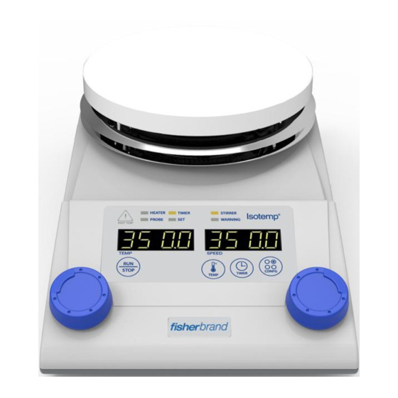
Functional Description Section 2 The Fisher Scientific Isotemp RT AVCD HPS model offers temperature and control by external temperature probe. This unit also boasts quick heat-up time thanks to ample heating capacity as well as the superb heat transfer rate enabled by the tightly integrated structure of the heater and the ceramic-coated aluminum alloy top plate. -
Page 10: Safety
Section 2 Functional Description • Offset Features To use your own thermometer for temperature control in specific applications, there can be some differences between the temperature of your thermometer and the displayed temperature of this unit. If needed, you can offset such temperature differences ranging from - 10°... -
Page 11: Convenience
Section 2 Functional Description • Error indication regarding external temperature sensor Safety In case of Error message, the Probe does not contain enough in media or on air. • A transparent shield is also provided to allow you to monitor your operations more safely by shielding you against decoupled stir bars or liquid splashes. - Page 12 Section 2 Functional Description • Smooth-start stirring system reduces magnetic bar decoupling. Convenience • Two support rods are provided to hold various kinds of devices such as temperature sensors, thermometers, laboratory glassware, etc. (optional). • User designation temperature range Your own temperature limit can be easily set and protect simple from controlling time or user mistake.
-
Page 13: Construction
Section 2 Functional Description Construction Figure 2-2. Front Components (1) Temperature probe This is PT100 sensor to check media temperature. (optional 2 different temperature probe series. Refer to Accessories list) (2) Heat sink (3) Heater knob (4) Control panel (5) Stirrer knob (6) Clamp holder (optional) (7) 3 Prong clamp (optional) (8) Support rod (optional) - Page 14 Section 2 Functional Description Construction Figure 2-3. Back Components (10) Power switch (11) Transparent Shield (optional) (12) Top plate (13) Threaded hole (14) Power socket (15) Temperature probe cap...
-
Page 15: Unpacking And Installation
If such damage is found, notify the carrier immediately. After unpacking, check to ensure that all the following parts and accessories are included in the package. If not, contact your dealer or Fisher Scientific immediately. Item Figure Quantity... -
Page 16: Pre-Startup Check
Section 3 Unpacking and Installation • Check the unit is balanced well. Pre-startup Check • Never install or use this instrument with or near to hazardous or flammable substances. • Do not install this instrument near any device that generates high frequency noise. -
Page 17: Control Panel
Control Panel Section 4 Figure 4-1. Control Panel Control Panel Although this instrument has a hot top warning indicator, which is turned on when HOT TOP the top plate temperature is over 50° C, do not rely on this indicator alone for your safety. - Page 18 Section 4 Control Panel Control Panel When this device is stop conduction, Configuration Functions can be set. When user wants to change mode, press the Config. Button with stirrer knob to clockwise turning. Then the mode can be switching in the following order.
-
Page 19: Check Power Status
Section 4 Control Panel Check Power Status (1) The following displays will appear in sequence together with a beep sound when the power cord is connected: • Note that the following display will also appear momentarily if the main power switch is off: (2) If you turn on the main power switch, the following display will appear in sequence: Connecting the... - Page 20 Section 4 Control Panel Temperature display windows are showed on “Sensor change” Connecting the message. After then, the display windows showed “Probe” measuring Temperature Probe temperature. (4) In case of separating temperature probe from main body, the temperature display windows are showed follow message; •...
-
Page 21: Stirrer Knob
Section 4 Control Panel Stirrer Knob When the stirrer knob is turned right, the device will start operating. And the stirrer function is operating individually without heating part. [Turning STIRRER operation, State indication LED] During STIRRER function operating, the stirrer value will be showed on display window. - Page 22 Section 4 Control Panel Run/Stop Button • Hot Top Warning Indicator will illuminate if the top plate temperature is over 50° C. • Be aware and careful of surface temperature. • Even if the instrument is turned off, the surface of the top plate and the vessel on top of it will remain very hot for some time.
-
Page 23: Temperature Setting
Temperature Setting The temperature setting procedures are proceeded by using TEMP button and the Heater Knob (left control knob). Step 1: Press the TEMP Button and check the display showing the current temperature setting. Step 2: If you want to change the temperature setting, select the desired temperature by turning and press the Heater Knob. -
Page 24: Temperature Setting During Operation
Temperature Setting Press TEMP Button or the Heater Knob during operation to see the set During Operation temperature. If you press TEMP Button, set temperature is shown on the right. After 15 seconds, the mode will be escaped automatically. If you press the Heater Knob, set temperature is shown on the left. After 3 seconds, the mode will be escaped automatically. -
Page 25: Resetting Set Temp During Operation
Resetting Set Temp Step 1: Press TEMP Button during operation. During Operation Step 2: Select the desired temperature by turning and press the Heater Knob. After 15 seconds, the mode will be escaped automatically. Or push RUN/STOP Button as shown below to escape the mode. Step 1: Push RUN/STOP Button during resetting the set temperature. -
Page 26: Maximum Heating Rate Setting
Maximum Heating Rate The higher the heating rate, the faster the heat up time but the wider Setting the temperature overshoot and undershoot. Therefore, if you want to reduce the temperature fluctuation, you need to limit the heating rate to a certain degree by limiting maximum heating rate. - Page 27 Timer Setting This unit provides two types of timer mode: immediate timer activation and delayed timer activation. (For selecting the timer mode, Refer to 4- 16 Selection of the Timer Mode) [Indicating LED status during timer is activating] You can stop timer by pushing RUN/STOP Button during timer’s activation.
-
Page 28: Timer Setting
Timer Setting [If you change the set temperature] Step 4: Then, the following display will appear asking whether you want to start the timer operation or not. If you want to save the new timer setting and to start the timer operation, you are required to change ‘NO’... -
Page 29: Check Remaining Run Time
Check Remaining Run Check the remaining run time during a timed operation by performing Time the following. (1) Press TIMER Button once to check the remaining time during timed operation. After 15 seconds, the mode will be escaped automatically. Escape of timer mode is shown as below. Step 1: Press RUN/STOP Button. - Page 30 Temperature Probe For temperature and timer setting on the Temperature Probe Control Control Mode Mode, see Temperature Setting and Timer Setting. In case of low smoke point media heating, High temperature limit value should be lower than smoke point. [Refer to High Temperature Limit Setting] (1) Temperature Probe Errors On temperature control mode if the external probe is in the air or is not...
-
Page 31: Configuration Mode
Configuration Mode Various configuration settings can be adjusted under the configuration mode such as heating mode, timer mode, maximum heating rate, low and high temperature limits, temperature unit, temperature offsetting, temperature control mode, and so on. You can enter this configuration mode by pressing the CONFIG Button when the unit is properly connected to a power outlet but not operating. - Page 32 Temperature Unit Step 2: Select the temperature unit conversion by turning the Stirrer Conversion (° C ↔° F) Knob as shown below. Step 3: Select either Celsius (° C) or Fahrenheit (° F) by turning and pressing the Stirrer Knob. Step 4: Save the selected temperature unit by using the Stirrer Knob as shown below.
-
Page 33: Selection Of The Timer Mode
Selection of the Timer Two different timer modes are provided: Immediate Timer Activation Mode (ti1) and Delayed Timer Activation (ti2). In case of the Immediate Timer Activation, timer starts immediately after setting the timer. In case of the Delayed Timer Activation, on the other hand, timer is activated only when the set temperature is reached. -
Page 34: Temperature Offsetting(Ofst/Ofsp*)
Selection of the Timer Mode Step 5: Terminate the configuration mode as described in Configuration Mode. • Refer to Top plate’s temperature influence on Heating bath and Erlenmeyer flask’s temperature for understanding of temperature relation between top plate and samples. Temperature Offsetting The temperature shown on the Actual Temperature Display is (OFST/OFSP*) - Page 35 Temperature Offsetting Step 1: Press the CONFIG Button (OFST/OFSP*) Step 2: Select the offsetting mode (OFST or OFSP) by turning the Stirrer Knob and press the Stirrer Knob as shown below. [OFST- Top plate offsetting] [OFSP- External temperature probe] Step 3: Select the offset value by turning the Stirrer Knob. The allowed ranges of the temperature offsetting are from -10 to +50°...
-
Page 36: Maximum Heating Rate Setting(Limt)
Temperature Offsetting (OFST/OFSP*) [OFST- Top plate offsetting] [OFSP- External temperature probe] Step 5: Terminate configuration mode as described in Configuration Mode. Maximum Heating Rate The higher the heating rate, the faster the heat up time but the wider Setting (LIMt) the temperature overshoot and undershoot. - Page 37 Maximum Heating Rate Step 4: Save the desired limit by using the Stirrer Knob as shown Setting (LIMt) below. [When you need to save the changes] If you don’t want to save it, press the Stirrer Knob when display shows “SAVE NO”.
- Page 38 Changing the High Temp Limits (t-H) Step 3: Change the limit to the desired value by turning the Stirrer Knob. Step 4: Save the desired limit by using the Stirrer Knob as shown below. [When you need to save the changes] If you don’t want to save it, press the Stirrer Knob when display shows “SAVE NO”.
- Page 39 Changing the Low Temp Note that the default setting of the low temperature limit [t-L] 0° C. If Limits (t-L) needed, however, you can set your own temperature limits. If, for example, you want to set the high temperature limit at 100° C, do as follows: Step 1: Press the CONFIG Button.
-
Page 40: Check Configuration Settings(List)
Changing the Low Temp Limits (t-L) Step 5: Terminate the configuration mode as described in Configuration Mode. • The allowed range of the temperature limit setting is 0° C ~ 350° C. • However, low temperature limit [t-L] set point should not be more than high temperature limit [t-H] set point. -
Page 41: Auto-Tuning(Pid Parameter Calibration)
Check Configuration Step 5: Terminate configuration mode as described in Configuration Settings (LISt) Mode. Auto-tuning (PID The PID parameters for temperature control can be automatically tuned Parameter Calibration) to take your specific operating circumstances into consideration. If you select User Mode [Coefficient], the unit will be operated with the auto tuning value. -
Page 42: Coefficient(Coef)
Auto-tuning (PID Step 4: Terminate configuration mode as described in Configuration Parameter Calibration) Mode. To cancel the auto-tuning during the process, turn off the main power switch. If cancelled, the Optimal Mode will be selected automatically with an alarm. Coefficient (COEF) Five user-selectable temperature control modes are provided for your convenience. - Page 43 Coefficient (COEF) [User-selectable temperature control modes] Providing the optimal balance between the heat up time to reach the target temperature and the Optimal Mode allowed fluctuation range of temperature overshoot and undershoot (factory default) Providing the fastest heat up time but the widest Fast Mode fluctuation range of temperature overshoot and undershoot...
-
Page 44: Default(Defa)
Coefficient (COEF) Step 5: Terminate configuration mode as describe in Configuration Mode. Default (DEFA) If you want to change the current settings back to the default settings described in Selection of Timer Mode, do as follows: Step 1: Press the CONFIG Button. Step 2: Select the default setting [dEFA] shown below by turning the Stirrer Knob. -
Page 45: Motor Minimum(Mmin)
Default (DEFA) Step 4: Terminate configuration mode as described in Configuration Mode. Motor Minimum (Mmin) You can limit the stirring speed to a certain point by setting the limit of maximum stirring speed. The range of speed adjustable is from 1 to 1000rpm. -
Page 46: Escape Mode(Esc)
If you don’t want to save it, press the Stirrer Knob when display shows Motor Minimum (Mmin) “SAVE NO”. [When you don’t need to save the changes] Step 5: Terminate configuration mode as described in Configuration Mode. Escape (ESC) Terminate the configuration mode. Step 1: Press the CONFIG Button. -
Page 47: Safety Device
Safety Device Section 5 (1) High and Low Temperature Limits The high temperature limit of the top plate is set to 350° C to protect you and your media. However, you can set your own high and low temperature limits to reduce operation time and also to avoid inadvertent mistakes. - Page 48 • If any overheat prevention activates or warning sound is alarming, turn off the power switch and disconnects the power cord first. Then allow your unit to cool down completely before operating it again.
-
Page 49: Maintenance
Maintenance Section 6 Inspection Interval Item Daily Weekly ● Connection status of power cord or plug ● Damages in power cord or plug ● Damages or cleanliness of top plate ● Cleanliness of main body and accessories Damages in switches, buttons, LED’s, dial ●... -
Page 50: Relocation
Cleaning Product Always make sure to keep top plate, main body, and accessories clean. Dirt and other foreign substances can cause fire or electric shock. Before attempting cleaning, - Disconnect the power cord from the power outlet and ensure that the instrument is cool enough, - Wipe with a soft dry cloth first to remove any foreign matter and, if not enough,... -
Page 51: Trouble Shooting
Damages in power cords, Replace the damaged part with a proper one power outlets or plugs. Internal circuit failure Contact Fisher Scientific for service. Disconnect all the appliances connected to the Repetitive tripping of the Electrical overload breaker first and reconnect them one by one to find the reason for the overload. - Page 52 Then, turn on the main circuit power switch. Button switch failure Contact Fisher Scientific for service. Internal circuit failure Contact Fisher Scientific for service. Probe is not enough Soak probe into the media more than 20mm of soaked into the media.
-
Page 53: Error Messages
Probe connection failure. Reconnect probe in right way. Probe lamp is not ON Damage due to chemical Contact Fisher Scientific for service. spill or overheat. If you see below “Error codes”, turn off the power. Restart after having the Error Messages unit rest enough. -
Page 54: Accessories
Accessories Section 8 NA Model EU Model Description 11676275 15336617 FS Temperature Probe (PT100, B Class, Max to 250℃) 11676278 15366617 FS Temp Probe Advncd (PT100, A Class, Max to 400℃) 11676269 15366607 FS Heating Bath 11676270 15376607 FS Transparent Shield (PC) 11676271 15386607 FS Support Rod (12Ø... -
Page 55: Transparent Shield & Heating Bath Assembly
Section 8 Accessories Transparent Shield & When necessary, the transparent shield and/or the heating bath can be Heating Bath Assembly easily assembled as shown below:... -
Page 56: Technical Specifications
Main Body Aluminum Material Top plate Ceramic coated aluminum ※ Unless otherwise specified, the above-mentioned data represent values at 25° C and 60% relative humidity. ※ Fisher Scientific reserves the right to make changes in design and specification without prior notice. -
Page 57: Disposing Of The Unit
Section 9 Technical Specifications Disposing of the Unit Disposing of your instrument must be done in an environmentally responsible way if it has been potentially exposed to bio-agents or radioactive samples. Failure to follow stringent requirements for instrument disposal may lead to actions against you and your organization. -
Page 58: Warranty Information
When used in laboratory conditions and according to these operation instructions and maintenance, this product is warranted for 24 months against defective materials or workmanship. The 24 month warranty period begins from the delivery date of this product. For product quality or performance issues, contact Fisher Scientific Customer Service. - Page 59 10-1...
- Page 61 North America United States Canada 1-800-766-7000 1-800-234-7437 fishersci.com fishersci.ca Europe Austria: Netherlands: +43(0)800-20 88 40 +31(0)20 4887 70 00 at.fishersci.com nl.fishersci.com Belgium: Norway: +32(0)56 260 260 +47 22 95 59 59 be.fishersci.com fishersci.no Denmark: Portugal: +45 70 27 99 20 +351 21 425 33 50 fishersci.dk pt.fishersci.com...
- Page 62 Find out more at fishersci.com © 2017 Thermo Fisher Scientific Inc. All rights reserved. Trademarks used are owned as indicated at fishersci.com/trademarks.
Need help?
Do you have a question about the Fisherbrand Isotemp RT AVCD HPS Advanced and is the answer not in the manual?
Questions and answers