Table of Contents
Advertisement
Quick Links
Advertisement
Table of Contents

Subscribe to Our Youtube Channel
Related Manuals for Fisher Scientific FB-50


Summary of Contents for Fisher Scientific FB-50
- Page 1 Sonic Dismembrator ULTRASONIC PROCESSOR Part No. FB-50 OPERATION MANUAL Rev. 8-10...
- Page 2 Rev. 8-10...
-
Page 3: Table Of Contents
Table of Contents Section Page No. Warranty Warnings Specifications Principles of Operation Description of Components / Functions of Controls 10-11 Preparation for Use 11-12 Operating Instructions 12-13 Accessories Maintenance 15-17 10. Troubleshooting 11. Service / Return of Equipment 12. Service Safety Certification form Rev. -
Page 4: Warranty
1. WARRANTY Your ultrasonic processor is warranted and backed by the manufacturer for a period of two years from the date of shipment against defects in material and workmanship under normal use as described in this instruction manual. During the warranty period, the manufacturer will, at its option, as the exclusive remedy, either repair or replace without charge for material and labor, the part(s) which prove to be defective, provided the unit is returned to us properly packed with all transportation charges prepaid. -
Page 5: Warnings
2. WARNINGS Please read the manual in its entirety. Necessary instruction and guidance are provided to help ensure the successful operation of this device. Your new ultrasonic liquid processor has been designed, built and tested to assure maximum operator safety. However, no design can completely protect against improper use that may lead to bodily injury and/or property damage. - Page 6 Symbols Caution, Risk of electric shock, Hazardous voltage. Caution, Risk of danger. Refer to User Manual. Rev. 8-10...
-
Page 7: Specifications
3. SPECIFICATIONS AC Adapter (supplied with System) Input Voltage 100 VAC - 240 VAC @ 50/60 Hz 1.5A Output Voltage 24 VDC 2.5A Rated Power 60 Watts Generator Input Voltage 24 VDC Rated Power 50 Watts Weight 3 lbs. (1.36 Kg) Dimensions 8"W x 8"L x 5"H 20cm x 20cm x 13cm... - Page 8 Environmental Pollution Degree Installation Category Operating Limits Temperature: 41 - 104ºF (5 - 40ºC) Relative Humidity 10 - 95% (Non Condensing) Altitude: 6,651 ft. (2000 m) Temperature: 35 -120 F (2 - 49 Shipping/Storage Relative Humidity 10 - 95% (Non Condensing) Ambient Pressure Extremes: 40,000 ft.
-
Page 9: Principles Of Operation
4. PRINCIPLES OF OPERATION The ultrasonic electronic generator transforms AC line power to a 20 KHz signal that drives a piezoelectric converter/transducer. This electrical signal is converted by the transducer to a mechanical vibration due to the characteristics of the internal piezoelectric crystals. The vibration is amplified and transmitted down the length of the microtip probe where the tip longitudinally expands and contracts. -
Page 10: Description Of Components / Functions Of Controls
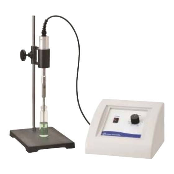
5. Description of Components / Functions of Controls The Model # FB-50 includes a standard 1/8” diameter microtip (#FB4422). FB-50 Front Panel Converter Converter Cable 1/8” Microtip Generator FB-50 Rear Panel Footswitch Convertor Cable Power Jack Connector Input Rev. 8-10... -
Page 11: Preparation For Use
FUNCTIONS OF KEYS, CONTROLS AND CONNECTORS FRONT PANEL ON Position – energizes the power supply. Power Switch OFF Position – de-energizes the power supply. Illuminates when the power supply is energized Amplitude Control Knob Controls the amplitude/intensity of vibrations at the probe tip REAR PANEL Footswitch Jack/Connector Connects to the footswitch cable. -
Page 12: Operating Instructions
WARNING For your personal safety, do not, under any circumstances, defeat the grounding feature of the power cord by removing the grounding prong. INSTALLING THE ULTRASONIC PROCESSOR The Ultrasonic Processor should be installed in an area that is free from excessive dust, dirt, explosive and corrosive fumes, and extremes of temperature and humidity. - Page 13 Operation: Continuous mode: 1. Ensure that the amplitude control knob is set to 0. 2. Set the convertor and probe assembly in a stand or hold the convertor in your hand. 3. Turn the unit on. 4. Immerse the microtip half way into the sample. If the probe is immersed to an insufficient depth, air will be injected into the sample, causing the sample to foam.
-
Page 14: Accessories
8. Accessories A. 5/64" probe (0.2 - 5ml), Catalog #FB4423 B. 1/8” probe (0.5 – 15 ml), Catalog #FB4422 C. Stand with clamp (20” x 10” x 10”), Catalog # FB460 D. Sound Enclosure with Clamp (20” x 10” x 10”), Catalog #FB432A E. -
Page 15: Maintenance
9. Maintenance It is recommended to periodically inspect the unit, both visually and physically, to insure optimum and safe performance. This inspection should be scheduled as a routine maintenance procedure, done with the unit power OFF and with the unit unplugged from the AC power source. Long exposure to acids or caustics results in corrosion of metal parts or components. - Page 16 Follow the steps below for attaching and detaching microtip probes: Disconnect probe from convertor. Use the wrench set provided with the system. Clean threaded stud. Use alcohol and a cotton swab to remove any debris on the threading of the connecting stud. Allow the alcohol to dry completely. 3.
-
Page 17: Troubleshooting
System Cleaning Instructions The generator and converter may be cleaned using an acid-free cleaning solution (i.e. glass cleaner). Probes should be cleaned using isopropyl alcohol. Probes are made from titanium and can be autoclaved (the converter is an electrical part and cannot be sterilized in this manner). Before each procedure place the probe tip in water or alcohol and turn the power on for a few seconds to remove residue. -
Page 18: Service Safety Certification Form
SAFETY CERTIFICATION FORM Items being returned: ________________________________________________________________________ ________________________________________________________________________ ________________________________________________________________________ ________________________________________________________________________ ________________________________________________________________________ ____________________ Please check only one item below: ___ The equipment was never used or exposed to any radiological, biological or chemical agents and is safe to handle, use or dispose of. ___ The equipment was used but not in conjunction with or exposed to any radiological, geological or chemical agents and is safe to handle, use, or dispose of.
Need help?
Do you have a question about the FB-50 and is the answer not in the manual?
Questions and answers