
Related Manuals for Fisher Scientific Sonic Dismembrator FB-505


Summary of Contents for Fisher Scientific Sonic Dismembrator FB-505
- Page 1 Sonic Dismembrator ULTRASONIC PROCESSOR Part No. FB-505 OPERATION MANUAL Rev. 8-10...
- Page 2 Rev. 8-10...
-
Page 3: Table Of Contents
Table of Contents Section Page No. Warranty Warnings Specifications Principles of Operation 9-10 Description of Components / Functions of Controls 11-13 Preparation for Use Operating Instructions 15-19 Accessories Maintenance 21-23 10. Troubleshooting 11. Service / Return of Equipment 12. Service Safety Certification form 13. -
Page 4: Warranty
1. Warranty Your Ultrasonic Processor is warranted and backed by the manufacturer for a period of two years from the date of shipment against defects in material and workmanship under normal use as described in this instruction manual. During the warranty period, the manufacturer will, at its option, as the exclusive remedy, either repair or replace without charge for material and labor, the part(s) which prove to be defective, provided the unit is returned to us properly packed with all transportation charges prepaid. -
Page 5: Warnings
2. Warnings Please read the manual in its entirety. Necessary instruction and guidance are provided to help ensure the successful operation of this device. Your new ultrasonic liquid processor has been designed, built and tested to assure maximum operator safety. However, no design can completely protect against improper use that may lead to bodily injury and/or property damage. - Page 6 Symbols Caution, Risk of electric shock, Hazardous voltage. Caution, Risk of danger. Refer to User Manual. Rev. 8-10...
-
Page 7: Specifications
3. Specifications Generator 220 VAC – 240 VAC @ 50/60 Hz Input Voltage 100 VAC – 120 VAC @ 50/60 Hz 10 Amps max. 5 Amps max. Rated Current 15 Amps (slo-blo)* 8 Amps (slo-blo)* Fuse Rating Weight 15 lbs. (6.8 Kg) 8"W x 15"L x 9"H Dimensions 203 mm x 381 mm x 229 mm... - Page 8 Environmental Pollution Degree Installation Category Operating Limits Temperature: 41 - 104ºF (5 - 40ºC) Relative Humidity 10 - 95% (Non Condensing) Altitude: 6,651 ft. (2000 m) Temperature: 35 -120 F (2 - 49 Shipping/Storage Relative Humidity 10 - 95% (Non Condensing) Ambient Pressure Extremes: 40,000 ft.
-
Page 9: Principles Of Operation
4. Principles of Operation The ultrasonic electronic generator transforms AC line power to a 20 KHz signal that drives a piezoelectric converter/transducer. This electrical signal is converted by the transducer to a mechanical vibration due to the characteristics of the internal piezoelectric crystals. The vibration is amplified and transmitted down the length of the horn/probe where the tip longitudinally expands and contracts. - Page 10 increases (increased load on the probe), additional power will be delivered by the power supply to ensure that the excursion at the probe tip remains constant. The displayed wattage readings will vary as the load changes, however the amplitude will remain the same. The resistance to the movement of the probe determines how much power will be delivered to maintain amplitude.
-
Page 11: Description Of Components / Functions Of Controls
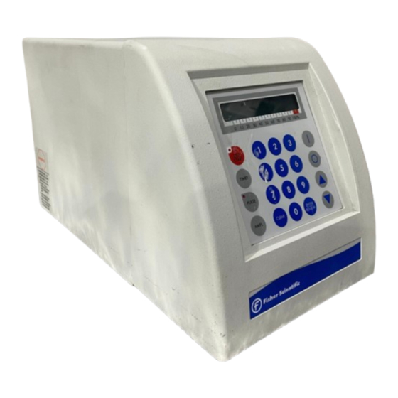
5. Description of Components / Functions of Controls The Model # FB-505 includes a standard 1/2” diameter probe (#FB4220). FB-505 Front Panel Converter Cable Converter ½” Horn with Generator replaceable tip FB-505 Rear Panel 9 Pin Connector Cooling Fan Footswitch Jack Converter Temperature... - Page 12 FUNCTIONS OF KEYS, CONTROLS, INDICATORS, AND CONNECTORS FRONT PANEL Displays prompts and the following control parameters: • Amplitude selected • Output power delivered to the probe in watts, and as percentage of the total power LCD display • Selected duration of processing •...
-
Page 13: Rear Panel
REAR PANEL 9 pin D-sub connector Connects to external actuation device, and enable power and (IO Port) frequency monitoring. Footswitch Connector Connects to the footswitch cable. Power Supply Connector Connects to the electrical line cord and encases the fuse(s). 9-PIN D-SUB CONNECTOR Pin No. -
Page 14: Preparation For Use
6. Preparation for Use INSPECTION Prior to installing the ultrasonic processor, perform a visual inspection to detect any evidence of damage, which might have occurred during shipment. Before disposing of any packaging material, check it carefully for small items. The ultrasonic processor was carefully packed and thoroughly inspected before leaving our factory. -
Page 15: Operating Instructions
7. Operating Instructions CAUTION Do not operate the power supply unless it is connected to the converter. • Never allow liquid to spill into the converter. • Do not allow a Microtip to vibrate in air. • Do not allow the vibrating Microtip to contact anything but the sample. •... - Page 16 clamp to any other portion of the convertor/probe assembly. If you are using an acoustic enclosure mount the convertor properly in the convertor collar. 9. Connect the converter cable to the power supply and then to the top of the convertor. Push the connectors in and turn the chrome rings clockwise ¼...
- Page 17 2. Immerse the probe tip into the sample liquid. Ensure that the probe is immersed to a depth that is at least 1.5 times the tip diameter. If the probe is immersed to an insufficient depth, air will be injected into the sample, causing the sample to foam. Processing at a lower intensity setting without foam is more effective than processing the sample with foam as ultrasonic cavitation will be diminished.
- Page 18 PULSER: By inhibiting heat build-up in the sample, the pulse function enables safe treatment of temperature sensitive samples at high intensity. The ON and OFF pulse duration can be set independently from 1 second to 59 seconds. During the OFF portion of the cycle, the red indicator on the PULSE key will illuminate.
- Page 19 REVIEW: The REVIEW function provides a “window” on the process by displaying various operating parameters without process interruption. Pressing the ENTER/REVIEW key repeatedly during processing will consecutively display the following information. a) Selected amplitude: e.g. Amplitude 40% b) Selected processing time and elapsed processing time: e.g.
-
Page 20: Accessories
8. Accessories A. 1/8" probe (0.5 - 15ml), Catalog #FB4418 B. 1/4” probe (5 – 50 ml), Catalog #FB4420 C. 1/2" probe with replaceable tip (10 - 250ml), D. 3/4" probe with replaceable tip (25 - 500ml), Catalog #FB4220 Catalog #FB4207 Note: 3/4“... -
Page 21: Maintenance
9. Maintenance It is recommended to periodically inspect the unit, both visually and physically, to insure optimum and safe performance. This inspection should be scheduled as a routine maintenance procedure, done with the ultrasonic processor power OFF and with the unit unplugged from the AC power source. - Page 22 Follow the steps below for attaching and detaching accessories: Disconnect probe from convertor. Use the wrench set provided with the system. Clean threaded stud. Use alcohol and a cotton swab to remove any debris on the threading of the connecting stud. Allow the alcohol to dry completely. 3.
- Page 23 Replacement Tip Removal Replacement Tip Tightening Replacement Tip Removal Replacement Tip Tightening *Note: When tightening a Microtip the tip must not be in contact with the work surface. Always have the tip extending off of the table or work surface to minimize stress to the tip. System Cleaning Instructions The generator and converter may be cleaned using an acid-free cleaning solution (i.e.
-
Page 24: Troubleshooting
10. Troubleshooting Your Ultrasonic Processor was designed to provide you with years of safe and dependable service. Nevertheless, because of component failure or improper usage, the possibility does exist that it might not perform as it should, shut down or stop working all together. The most probable causes for malfunction are listed below and should be investigated. -
Page 25: Service Safety Certification Form
SAFETY CERTIFICATION FORM Items being returned: ______________________________________________________________________ ______________________________________________________________________ ______________________________________________________________________ ______________________________________________________________________ ______________________________________________________________________ ______________________________ Please check only one item below: ___ The equipment was never used or exposed to any radiological, biological or chemical agents and is safe to handle, use or dispose of. ___ The equipment was used but not in conjunction with or exposed to any radiological, geological or chemical agents and is safe to handle, use, or dispose of. -
Page 26: Addendum
Addendum Converter Cooling Continuous sonication will cause both the probe and sample temperature to increase. The heat will transfer up to the converter. If the converter overheats the internal crystals can crack and the entire converter will require replacement. Converter damage due to overheating is not covered under warranty. - Page 27 Frequently Asked Questions (FAQ) Probe size vs. Sample volume Selecting the proper size probe is a critical factor when sonicating a sample. The sample volume to be processed must correlate with the tip diameter. Each probe has a recommended sample volume range. This range may overlap with other probes.
- Page 28 below the tip and become processed. The probe should be immersed at least 1.5 times the tip diameter. Before processing actual samples, it is recommended to test the probe in a vessel filled with water to observe the ultrasonic energy and the flow pattern of the liquid. During this test you can adjust the probe’s depth until you see adequate mixing and movement of the water.
Need help?
Do you have a question about the Sonic Dismembrator FB-505 and is the answer not in the manual?
Questions and answers