Table of Contents
Advertisement
Quick Links
Advertisement
Table of Contents

Related Manuals for Signode BHC


Summary of Contents for Signode BHC
- Page 1 COMBINATION STRAPPING TOOL...
-
Page 2: Table Of Contents
(.016-.035") Adjusting the weld time Initial setting of strap tension Adjusting the strap width Tension wheel Maintenance Changing the tension shoe Changing tooth plate 8 Parts list Exploded drawing 9 Recommended spare parts BHC Automatic Strapping Tool Part No. 423750... -
Page 3: General Information
GENERAL INFORMATION CAUTION! These operating instructions are intended to simplify familiarization with the strapping tool and Used where there is the possibilities of application for the intended danger to life and health. purpose. The operating instructions contain important information concerning the safe, proper and efficient use of the strapping tool. -
Page 4: Safety Instructions
SAFETY INSTRUCTIONS Inform yourself! Caution: Read the operating Only strap packed instructions carefully goods! Do not put hands or other parts of the body between the strap and the package during the Protect yourself[ strapping process. When operating the tool, wear eye, face and hand Original spare parts protection (cut-proof... -
Page 5: Description
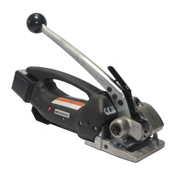
DESCRIPTION 4.1 DESIGN 1. Rotary knob "Strap tension" 2. Sealing lever 3. Battery 4. Push button 'Strap tensioning" 5. Cutting device 6. Tension shoe 7. Tension wheel 8. Potentiometer 'Initial setting, strap tension" 9. Potentiometer "Welding time" 10. Indicator "Battery" 11. -
Page 6: Initial Operation
INITIAL OPERATION 5.1 BATTERY CHARGER The main voltage must comply with the specifications on the rating plate, 230 V (115 V) battery chargers can be operated at 220 V or 240 V (I10 V). The battery charger is suitable only for charging NTC batteries from the Bosch range of tools. -
Page 7: Operating Instructions
OPERATING INSTRUCTIONS 6.1 OPERATING THE TOOL Insert charged battery and close the bow spring Fig 5 Place the strap around the package and hold it with the left hand so that the lower strap lead is approx. 20 cm (8") away from the hand. Take the tool with the right hand and press the lever towards the handle. - Page 8 Insert the strap from coil holder between the tension wheel (7/3) and the tension shoe (712). Then insert the strap into the slot of the cutting device (711) until stop is reached. Fig 7 Press the yellow button with the right thumb, until the required strap tension is reached.
- Page 9 This tool is provided with a safety logic device to prevent accidental starting of the welding process (e. g. when carrying the tool with the sealing lever). For this reason the strap must first be tensioned to a minimum tension to start the welding process (press yellow button).
-
Page 10: Preventative & Corrective Maint
PREVENTATIVE & CORRECTIVE MAINTENANCE 7.1 CHANGING THE BATTERY If the red signal lamp (12/1) is lit continuously, the battery must be charged (see chapter Continuous red light 5.2). Open bow spring and remove discharged battery. Insert charged battery and lock with bow spring. -
Page 11: Initial Setting Of Strap Tension
7.3 INITIAL SETTING OF STRAP TENSION Remove plastic cover (15/1). The initial setting of the strap tension can be set fully variably with a screwdriver (no 1) depending on the quality and size of the strap. The strap tension is increased by gradually turning the screw clockwise ( 200 N) or decreased by turning counter-clockwise (800 N). -
Page 12: Tension Wheel Maintenance
7.5 CHANGING & CLEANING THE TENSION WHEEL Removal • Open bow spring (1811) and remove battery (18/6). • Release three countersunk screws (18/2) and remove protective lid (1 8/3). • Press lever (1 8/5) against the handle and carefully withdraw tension wheel (18/4). •... - Page 13 BHC PARTS LIST PART# DESCRIPTION PART# DESCRIPTION 423714 Base plate 423645 Motor 423602 Needle bushing 423646 Connecting rod 423603 Set screw, M 4 x 8 423647 Link 423715 Housing part right 423648 Bolt 423605 Cover, ø 10 423649 Retaining ring 423716 Cover, ø...
-
Page 14: Parts List
BHC PARTS LIST, CONTINUED PART# DESCRIPTION 423692 Knife complete 423693 Torsion spring 423774 Stroke lever 423694 Bushing 423695 Bolt 423696 Bolt 423775 Printed circuit board 423699 PT-Screw, KA 35 x 12 423706 Battery, 12 V 423707 Charger, 230 VEU 423708...
Need help?
Do you have a question about the BHC and is the answer not in the manual?
Questions and answers