
Related Manuals for Xylem YSI 2500


Summary of Contents for Xylem YSI 2500
- Page 1 USER MANUAL 525021 YSI 2500 Biochemistry Analyzer OPERATIONS AND MAINTENANCE MANUAL...
-
Page 2: Table Of Contents
Table of Contents Introduction ............................1-1 Description ..........................1-1 General Specifications ......................1-1 Safety ..............................2-1 Important Safety Instructions ....................2-1 Explanation of Symbols ......................2-2 Getting Started ........................... 3-1 Unpacking ..........................3-1 Warranty Card ........................3-2 What You Need ........................3-2 Major Components ......................... - Page 3 Service ..........................6-20 6.2.1 Sipper ..........................6-20 6.2.2 Module..........................6-23 Data ............................6-27 6.3.1 Plate ..........................6-27 6.3.2 Calibration ........................6-30 Help ............................6-30 6.4.1 About ..........................6-30 6.4.2 Software ......................... 6-31 Connectivity .......................... 6-33 6.5.1 Ethernet Port ........................6-33 6.5.2 RS232 Port ........................
- Page 4 Storage ............................... 9-1 Instrument Storage ......................... 9-1 Enzyme Membrane Storage ....................9-1 Instrument Handling/Transport ....................9-1 Troubleshooting ........................10-1 10.1 Printout Information ......................10-2 10.2 Troubleshooting Chart ......................10-4 Principles of Operation ......................11-1 11.1 Enzyme Sensor Technology ....................11-1 11.2 Measurement Methodology ....................
-
Page 5: Introduction
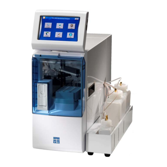
1 Introduction Description The 2500 Biochemistry Analyzer is a laboratory instrument intended for use in research, food-processing and bioprocessing applications. THE 2500 Analyzer IS NOT FOR HUMAN MEDICAL DIAGNOSTIC USE OR FOR HUMAN PERFORMANCE EVALUATION. The 2500 Analyzer can be set up to measure glucose and/or lactate in a sample. User Features Slim modular design Easily expand analytes or chemistries... -
Page 6: Safety
2 Safety Important Safety Instructions DO NOT PLUG THE INSTRUMENT IN AT THIS TIME. You should apply power only when directed to do so in the setup instructions. 1. Use ONLY the line power cord supplied with the instrument. When directed to, connect the plug to a matching three- pronged wall receptacle. -
Page 7: Explanation Of Symbols
Explanation of Symbols Warning indicates that misuse of the instrument could result in WARNING death or serious injury to a person. Un avertissement indique qu'une mauvaise utilisation de l'instrument peut entraîner la mort ou une blessure grave chez une personne. AVERTISSEMENT Caution, consult accompanying documents. -
Page 8: Getting Started
3 Getting Started Unpacking When you unpack your new 2500 Analyzer for the first time, check the packing list to make sure you have received everything listed. Note that reagents for the 2500 Analyzer are not packaged in the same carton as the instrument. If there is anything missing or damaged, call the dealer from whom you purchased the 2500 Analyzer. -
Page 9: Warranty Card
Warranty Card Please complete the Warranty Card or register your purchase online at www.ysi.com/customer-support/warranty-card This will record your purchase of this instrument in our computer system. Once your purchase is recorded, you will receive prompt, efficient service in the event any part of your 2500 Analyzer should ever need repair. What You Need Several things are needed in order to analyze samples using the 2500 Analyzer. - Page 10 Display Graphical color LCD covered by a touch screen USB ports The USB ports allow a flash drive to be connected to the 2500 Analyzer to download sample results or upgrade the instrument’s software. A USB port is located on the right side of the display. An additional USB port is located on the rear of the instrument.
- Page 11 Sample module Made of clear acrylic plastic. Sensor probes are screwed into either side of the module. The immobilized enzyme membranes are mounted on O-rings which act as fluid seals. A reference or auxiliary electrode is housed in the temperature probe and positioned at the back of the Sample module.
-
Page 12: Basic Setup
4 Basic Setup The following list describes the basic steps necessary for sampling with the 2500 Analyzer. 1. Install Bottle Rack 2. Connect Printer (optional) 3. Connect AC Power 4. Align Sipper 5. Prepare and Install Buffer solution 6. Install Calibrator Solution 7. -
Page 13: Connect Printer
Connect Printer Connect the optional YSI 2901 Printer to the 2500 Biochemistry Analyzer using the data cable provided. The small RJ12 connector plugs into the bottom of the printer and the large DB9 connector plugs into the RS232 port on the back of the analyzer. - Page 14 4. Since the top cover of the instrument is removed, the message below will appear. 5. Touch [OK] to confirm, then touch the Settings icon. 6. Touch the Interlocks [On] button.
-
Page 15: Align Sipper
Touch [Yes] to confirm and disable the safety interlocks. 8. Touch [X] in the top left of the screen to return to the main display. Align Sipper It is very important that the sipper be accurately adjusted. WARNING: Keep your hands clear of the sipper while the instrument is in operation. 1. - Page 16 5. If the sipper is not centered, touch [Position] and use the arrow buttons to center the sipper. 6. Make certain the Sipper is centered, then touch [Save] at the bottom of the adjustment window. Sipper Adjustment Position Figure 4-2 7.
- Page 17 8. Once the sipper enters the sample module without hitting the cone, touch [Depth] to set the sipper depth. The Select Location screen will appear. 9. Select [Module 1]. The tip of the sipper should be right at the top of the module. Use the arrow buttons to lower or raise the sipper until the tip of the sipper is even with the top of the module.
-
Page 18: Prepare And Install Buffer Solution
12. Once you have aligned the sipper properly and set the depth, sipper alignment for the Module is complete. 13. Check the sipper alignment for any rack or plate you intend to use at Station 1 (see 6.2.1 Sipper). 14. Touch [X] at the top left of the screen to return to the main display. After you have aligned the sipper with the module, return to the Settings screen and touch the Interlocks button and change it back to [On] to enable the safety interlocks. -
Page 19: Prime The Fluid System
1. Unscrew and remove the lid from the empty calibrator bottle. IMPORTANT: make every effort to avoid contamination of the lid and level sensor assembly. 2. Mark the date of installation on the label of the new bottle of YSI calibrator solution (the working life is 30 days). 3. - Page 20 Probe B Probe A Probe A is on the left when looking in from the side of the instrument Figure 4-3 To install a membrane: 1. Make sure the top cover is removed from the instrument. 2. Next, unscrew the appropriate enzyme probe retainer and gently pull the probe out of the module. 3.
-
Page 21: Configure Instrument
Configure Instrument Before operating the 2500 Analyzer, you must set the instrument parameters. 4.9.1 Assign Chemistries to Probes 1. From the main display, touch Configure. 2. Touch the Probe A membrane button to select the chemistry you want to measure. 3. -
Page 22: Buffer
(see Section 7 Chemistry Setup for details). NOTE: Changing chemistry assignments will change the calibrator value back to the default settings. 4.9.2 Buffer The YSI 2500 always uses YSI 2357 Buffer. 4.9.3 Calibrator 1. Touch the Calibrator button and select the appropriate calibrator, 2776 or 2747. -
Page 23: Check Probe Currents
2. Touch [Save]. 4.10 Check Probe Currents 1. From the [Module] tab of the Service screen, touch the [Flush] button to flush the sample module with buffer. Enzyme Probe Currents 2. Observe the probe current values (baseline). They must be below 6 nA and stable. 3. -
Page 24: Running The Instrument
5 Running the Instrument Perform Daily Operational Checks To ensure that your 2500 Analyzer is operating properly, perform the Membrane Integrity and Linearity checks on a daily basis before running samples. 5.1.1 Enzyme Membrane Integrity Test Run YSI 2363 Potassium Ferrocyanide (FCN) Standard as a sample to determine if your enzyme membranes are structurally intact. - Page 25 7. Touch the [Batch] button. 8. Select the chemistries that require the FCN test. 9. To change the Batch Name from the default value of TestBatch- #, touch the [TestBatch- #] button. The keypad window will appear. 10. Type your new batch name and touch [DONE].
-
Page 26: Linearity Test
11. Touch [Save] to save the batch. 5.1.2 Linearity Test 12. Pour small amount of each linearity standard in a test tube or multi-well plate. 13. Touch additional sample locations and create new batches for the linearity tests. 14. For the daily linearity checks, select only the chemistry that corresponds to the linearity standard in that sample location. -
Page 27: Results
5.1.3 Results 20. Touch the Results tab 21. Select a sample location. Select a sample 22. Touch a chemistry to show details Select to show details... -
Page 28: Sample Preparation
23. Listed in table 6-1 below are the recommended FCN limits. a. Values less or equal to FCN limits indicate integral membranes b. Values greater than FCN limits indicate membrane structural failure c. If readings are high, recalibrate and repeat all the steps above to confirm. d. - Page 29 Arrows 2. Touch [New] and choose from the selection of supported racks and plates. Alternatively, use the arrows to scroll through the saved racks and plates until you find the type that you are using. 3. You may rename the rack/plate by touching its ID. 4.
-
Page 30: Export
13. You may also create one or more batches for samples. Alternatively, you may create a separate rack for sample batches. 14. Touch [Close] when all batches are created. 5.3.2 Export 1. To save your plate configurations to a flash drive, touch [Export]. 2. -
Page 31: Run Samples
Figure 5-2 5.3.3.2 R4 or R8 Tube Racks 1. Open the front door of the instrument. 2. Insert the R4 or R8 tube rack into the cavity just inside the front door. 3. Insert your sample tubes into the tube rack you installed. R8 Tube Rack Figure 5-3 5.3.4 Run Samples... -
Page 32: Run Stat
Virtual Printer 2. The virtual printer window displays details of previous samples and calibrations. 3. Use the arrow buttons to scroll the printer window. 4. Touch [Print Configuration] to send the current analyzer setup to the printer. Run Stat A Stat sample at Station 2 runs without stopping a plate analysis that is in progress. NOTE: The Sipper is not designed to pierce septa. - Page 33 4. Select the chemistries and units for the sample. 5. Touch [Save] to return to the Run Stat screen. The type of sample you configured will be underlined. 6. Touch (Start) to run the highlighted (Stat or Syringe) sample at Station 2. If a Station 1 batch is in progress, the Stat sample will run as soon as the current sample is finished.
- Page 34 8. The Stat sample results are displayed on the Run Stat tab. Stat sample results 5-11...
-
Page 35: Advanced Functions
6 Advanced Functions Settings Touch [Settings] to display the settings screen as shown below. The Settings screen includes System and Display tabs. 6.1.1 System Touch the [System] tab (if not already selected). The System tab is used to adjust calibration settings, enable sipper and bottle fluid detection, and interlocks. - Page 36 The default Auto-calibration settings are shown above. You may alter any of these parameters to suit your application, however, you may compromise precision and/or accuracy when doing so. YSI’s stated specifications are based on the default settings. These selections are provided as part of the overall concept of the 2500 Analyzer flexibility. To change the value of a Calibration parameter, simply touch the value to open the numeric keypad.
- Page 37 Enter the Hour each day that the instrument should calibrate in 24 hour format (0–23), then touch [OK]. Touch the Minute button [0] and enter the Minutes. Touch [OK]. After you have finished making your changes, touch the [Save] button. 6.1.1.2 Sipper Options Touch the Sensitivity [High] button and change it to [Low] for samples with high conductivity.
-
Page 38: Display
Touch the Dynamic Fluid Depth [On] button and change it to [Off] to disable sipper fluid detection and use fixed depth at sample stations. Touch the “When no fluid detected” button and select the sample fluid detection mode you prefer: [Error] Produce an error when no sample is detected (no sample result). - Page 39 The Display tab is used to select the type of sample and calibration reports, print the configuration, adjust the display brightness, select your language, calibrate the touch screen, select the clock format, and enable/disable the screensaver. 6.1.2.1 Printer Reports To change the Analysis or Calibration Reports, touch the button below it to cycle through the selections— Brief, Detailed, or None.
- Page 40 Select your language from the available choices. 6.1.2.5 Touch Screen Calibration The touch screen is calibrated at the factory and should not require user calibration. Touch the [Calibrate Display] button to enter touch screen calibration. Using a stylus, touch and hold the center of the red flashing that appears at each corner of the display until appears.
- Page 41 6.1.2.6 Clock Format Touch the Clock Format button. Touch the Hour Format button and select [12-hour] or [24-hour] clock format. Touch the Date Format button and select [DD/MM/YYYY] or [MM/DD/YYYY] date format. Touch the [Save] button to save your changes. 6.1.2.7 Screensaver Touch the [Screensaver] button.
-
Page 42: Date/Time
Touch the number of Minutes button [60] next to “Start after.” Enter the number of minutes that the instrument should remain idle before enabling the screensaver, then touch [OK]. Touch the [Save] button. 6.1.3 Date/Time Time To set the date/time, touch the time button on the main screen. 6-19... -
Page 43: Service
Touch the current date on the calendar to select it. Touch the Hour button and enter the current hour in 24 hour format (0–23), then touch [OK]. Touch the Minute button and enter the current minute, then touch [OK]. When you have finished entering the date and time, touch [OK] to return to the main display. Service Touch [Service] to display the Service menu. - Page 44 Location To align the sipper at other locations, touch the button under Location. Touch the button for your location, [Station 2] for example. Touch the [Position] button and use the arrow buttons to align the sipper with the selected location. 6-21...
- Page 45 Touch [Save] to save the position. Touch [Inject] to lower the sipper and test the alignment, then touch [Retract] to raise the sipper back up. If necessary, touch [Position] and repeat the adjustment. 6.2.1.2 Depth Touch [Depth] and select the location. The sipper will move to the selected location. Sample Module: use the up and down arrows to set the tip of the sipper even with the top of the Module.
-
Page 46: Module
Touch [Save] to confirm the position. 6.2.2 Module From the Service menu, touch the [Module] tab. The Module tab displays the status of the probes, probe current for each enzyme probe, and the temperature. The probe current is expressed in nA (nanoamperes, 10 amperes), a very low level of electrical current. - Page 47 necessary, touch the [Flush] button to flush the sample module again. Note that when the instrument is first powered up, it may take several hours for the baseline currents to drop below 6 nA. 6.2.2.3 Calibrate The 2500 Analyzer will automatically calibrate before running a sample batch. You may initiate manual calibration from the [Modules] tab of the Service screen by touching the [Calibrate] button.
- Page 48 6.2.2.4 Controls Buffer Pump Touch the [ON] button under B1 pump. The buffer pump will run. Touch the [OFF] button to stop the pump. Calibrator Pump Touch the [ON] button under Cal 1A Pump. The calibrator pump will run. Touch the [OFF] button under the pump to stop it. 6-25...
- Page 49 NOTE: Prime the calibrator bottle daily to remove air bubbles from the tubing and deliver fresh calibrator to the cal well! When you have finished priming the fluid pumps, touch the [X] button to return to the Main display. Stirbar The StirbBar screen is used to adjust the speed of the stir bar.
-
Page 50: Data
Data From the Main display, touch [Data]. 6.3.1 Plate Historical plates of sample data are displayed under the Plate tab. Touch the scroll buttons to page through plates. Touch a specific plate to highlight it, then touch [View] to display the sample data for the selected plate. Sample data for the first sample in the batch is displayed. - Page 51 Touch any other sample location to display the sample data. Touch the sample result to show details. Select to show details Select sample Touch [X] to return to the Data screen. 6.3.1.1 Plate Name Filter Touch the Name button and enter a plate name to filter the data. Only plates that begin with that name will be displayed.
- Page 52 6.3.1.2 Export Check the To Export box for each batch that you would like to export to a flash drive. Plug a flash drive into the 2500 Analyzer’ USB port. An icon in the top right of the display indicates a flash drive is installed.
-
Page 53: Calibration
6.3.2 Calibration Touch the Calibration tab. Plug a flash drive into the 2500 Analyzer’ USB port. Select a date range, then press the [Export] button to send calibration data to the flash drive. When you have finished exporting data, touch the [X] button to return to the Main screen. A folder named YSI\BiochemistryAnalyzer will be created on the flash drive. -
Page 54: Software
6.4.1.1 Machine ID The default Machine ID is the instrument serial number. Touch the Machine ID button to enter a custom ID for this instrument. Enter the new ID and touch [Done]. NOTE: The Machine ID is used as the folder name and file name for data files. The 2500 Analyzer software can be updated via a flash drive inserted into the USB port. - Page 55 Press [Export Config] to save the current instrument configuration to the flash drive. NOTE: The configuration file can be imported at a later date to restore the instrument configuration. 6.4.2.2 Backup Press [Backup] to backup the current instrument setup, database, and log files to the flash drive. 6.4.2.3 Restore Press [Restore] to restore a previous backup file for this analyzer from a flash drive.
-
Page 56: Connectivity
The YSI 2500 Updater will be displayed. Touch the [Update Application] button to install the new software. When the Installation is complete, the analyzer will reboot. Remove the flash drive. NOTE: Updating the software will clear all sample data. After updating the software, the sipper must be aligned with all positions. - Page 57 Router (Private Network Connection) Connect one or more 2500 Analyzer instruments to a router (DHCP server) via the RJ45 Ethernet port. Accessing Stored Data Access the data stored in a 2500 Analyzer connected to a LAN or router via ftp. See 6.4.1 About to view the instrument’s current IP address.
-
Page 58: Rs232 Port
If you are unable to connect via ftp, make sure the “Passive ftp” option is not checked under Advanced Internet Options on your computer: Sample and calibration data files are stored in the Samples folder of the 2500 Analyzer. The file names are: BioSample_Machine ID.csv BioCalibration_Machine ID.csv 6.5.2 RS232 Port... -
Page 59: Chemistry Setup
7 Chemistry Setup In this section, you will learn about each standard chemistry setup for single chemistry configurations and then dual chemistry configurations. In order to configure your instrument to measure a particular chemistry analyte, you need to: • Approximate the analyte concentration or range of concentrations to be measured. •... -
Page 60: D-Glucose (Dextrose)
7.2.1 D-Glucose (Dextrose) This is a direct reading of glucose in solution at the enzyme sensor. The enzyme glucose oxidase is immobilized in the enzyme membrane. Glucose + O + D-Glucono-δ-Lactone Glu Oxidase System Buffer Special Considerations: YSI 2357 • Calibrator Std YSI 2776 If sample dilution is required, use reagent water. -
Page 61: L-Lactate
7.2.2 L-Lactate This is a direct reading of L-Lactate (L-Lactic Acid) in solution at the enzyme sensor. The enzyme L-Lactate Oxidase is immobilized in the enzyme membrane. L-Lactate + O + Pyruvate L-Lac Oxidase Special Considerations: System Buffer YSI 2357 •... -
Page 62: Simultaneous Glucose And L-Lactate
7.2.3 Simultaneous Glucose and L-Lactate Refer to the sections above on Glucose and L-Lactate for theoretical and special considerations. Then follow the instructions below to set up your instrument for simultaneous determination. A Probe B Probe Chemistry Glucose L-Lactate System Buffer YSI 2357 Calibrator Std YSI 2776... -
Page 63: Operational Checks And Maintenance
8 Operational Checks and Maintenance Cleaning, Disinfecting, and Decontaminating Proper precautionary lab practices should be followed when handling biological hazards. Authorized cleaning and disinfecting agents include: • Sodium hypochlorite, 0.5% free available chlorine • Isopropanol, 70% • Ethanol, 70% • NaOH, 0.5N Authorized rinsing agents include: •... -
Page 64: Check The Buffer Bottle
8.2.3 Check the Buffer Bottle Replace the buffer if the bottle is low or the buffer has been in the instrument longer than 1 week. Clean the buffer bottle and cap with an authorized cleaning solution (see Section 8.1), then rinse well with authorized rinsing agent (see Section 8.1) before installing fresh buffer. -
Page 65: Bottle Cap Cleaning
Remove and discard the authorized cleaning solution, then rinse the bottle thoroughly with authorized rinsing agent (see Section 8.1). Next, add authorized rinsing agent to the bottle, reinstall the Buffer bottle inside the bottle tray. From the Service screen, Module tab, touch [Off] to prime the buffer pump for 3 to 5 minutes to rinse the tubing. After 3 to 5 minutes, touch [On] to turn the pump off. -
Page 66: Waste Module Cleaning
Thumbnuts Enzyme Probe Enzyme Probe Sample module Figure 8-1 Unscrew and remove the enzyme probes and the temperature probe from the sample module. Remove the sample module. Remove and discard the small magnetic stir bar inside the module. Immerse the module in the authorized disinfecting agent (see Section 8.1) for a maximum of 10 minutes. -
Page 67: Sipper Pump Seal Replacement
8.4.3.1 Sensor Maintenance It is necessary to maintenance the enzyme sensors when the PM kit is installed and periodically as needed. 1. Remove the enzyme Membrane and hold the probe with the electrodes facing up. 2. Wad a small portion of a lint free tissue and wet it with 70% isopropyl alcohol. 3. -
Page 68: Bottle Tubing
RED O-RING SPACER RED O-RING Sipper pump seal replacement Figure 8-4 Reassemble the pump, position the plunger as shown in Figure 8-5 and install it back on the instrument. Sipper pump plunger position Figure 8-5 WARNING: When re-installing the pump head assembly, the plunger MUST extend at least 1/2″... -
Page 69: Pump Tubing Replacement
Hex Screws Pump Cover (right side) Figure 8-6 Sipper Pump Buffer Pump BLUE Cal Pump Pumps – Right side Figure 8-7 8.4.6 Pump Tubing Replacement Tubing life depends on instrument usage. The buffer and calibrator pump tubing should be replaced at least every 6 months or 1000 hours sample ready. - Page 70 8.4.6.1 Buffer Pump Tubing Pull out firmly on the top edge of each pump head cover. The pump head cover should snap off. See Figure 8-8 and Figure 8-9 below. Figure 8-8 Remove the pump tubing from the pump. Install Buffer Tubing Apply plenty of buffer grease (included with the new buffer pump tubing) to the new buffer pump tubing.
-
Page 71: Install Waste Module
8.4.7 Install Waste Module After cleaning, flush the waste module with copious amounts of authorized rinsing agent (see Section 8.1) to remove any traces of the disinfecting agent. Install new O-rings in the base plate under the waste module. Reinstall the waste module using the three hex screws previously removed. - Page 72 Cover Screw Remove the screw holding the sipper arm cover, then raise the cover up and slide it out of the sipper arm. Disconnect the tubing from the sipper. Unscrew the sipper cone, slide it down and remove it from the sipper. Loosen the two needle mount screws two turns, then remove the sipper by sliding it straight out of the mounts.
-
Page 73: Calibrate Sipper
8.4.11 Calibrate Sipper Align the Sipper with the sample module as described in Section 4.4 Align Sipper. 8.4.12 Install Bottles Temporarily place the bottle tray next to the instrument and install the bottles. Connect the tubing and cables to the bottles. -
Page 74: Storage
9 Storage During normal use, the 2500 Analyzer should be left with the power on at all times. It should also have an adequate supply of buffer. This will keep the enzyme probes polarized and ready for use and prevent the module from drying out. Instrument Storage If the 2500 Analyzer is not going to be used for 2 weeks or longer, remove the buffer and calibrator solutions from the bottles and replace them with authorized rinsing agent (see Section 8.1). -
Page 75: Troubleshooting
10 Troubleshooting This section provides a systematic approach to establishing the cause of an instrument malfunction. Before taking any corrective action, be certain you have collected as much pertinent information as possible. To establish probable cause, you should: • Review any error/warning messages displayed. They should indicate any problems. •... -
Page 76: Printout Information
25.9 ----------------------- ----------------------- Volume (uL) 1B:Lactate 0.50 g/L Dilution Factor IB nA 0.88 Fri 9/9/2018 10:59:37 NPL nA 9.81 YSI 2500 – 15F000025 FB nA 0.76 ======================= PL Slope nA/m 0.42 IB Shift -1.95% NPL Shift 1.64% ======================= Temp (C) 25.9... - Page 77 Sample Report (Brief) Calibration Report (Brief) ======================= ======================= Sample Results Report Cal Report [2] ======================= ======================= Batch: Test Batch-1 1A:Glucose 2.50 g/L Analyte: P96_A01 IB nA 3.24 ----------------------- NPL nA 17.63 1A:Glucose 4.82 g/L NPL Shift -0.64% 1B:Lactate 1.82 g/L ----------------------- Fri 9/9/2018 10:59:37 1B:Lactate...
-
Page 78: Troubleshooting Chart
10.2 Troubleshooting Chart SYMPTOM: MEASUREMENT ERROR: IB Level Error POSSIBLE CAUSE: Pinched, leaking or disconnected tube. ACTION: Fix or replace tubing. SECTION: 8.4.6 Pump Tubing Replacement POSSIBLE CAUSE: Sipper misaligned. ACTION: Check Sipper alignment. SECTION: 4.4 Align Sipper POSSIBLE CAUSE: Sipper pump not operating properly. - Page 79 POSSIBLE CAUSE: Newly installed enzyme Membrane. ACTION: Enter probe service and check probe currents. SECTION: 6.2.2 Module POSSIBLE CAUSE: Newly installed probe. ACTION: Enter probe service and check probe currents. SECTION: 6.2.2 Module POSSIBLE CAUSE: Calibrator solution out of spec: contaminated or installed for more than 30 days.
- Page 80 POSSIBLE CAUSE: High waste level. ACTION: Empty waste bottle. SECTION: 8.2.1 Empty the Waste Bottle POSSIBLE CAUSE: Bubbles in buffer or calibrator bottle tubing. ACTION: Prime bottle. SECTION: 4.7 Prime the Fluid System SYMPTOM: INTERNAL FAILURE: Unable to Calibrate POSSIBLE CAUSE: Air bubbles in calibrator tubing.
- Page 81 SYMPTOM: ERROR: No Fluid Detected POSSIBLE CAUSE: Low sample level. ACTION: Increase sample level in test tube. POSSIBLE CAUSE: Sipper Depth set too high at sample station. ACTION: Adjust sipper depth. SECTION: 4.4 Align Sipper POSSIBLE CAUSE: Calibrator bottle not primed. ACTION: Prime calibrator bottle.
- Page 82 SYMPTOM: ERROR: Motor Failure POSSIBLE CAUSE: One of the motors is jammed. ACTION: Enter motor service and cycle the suspected motor. SECTION: 6.2 Service POSSIBLE CAUSE: Worn sipper pump seals. ACTION: Replace seals. SECTION: 8.4.4 Sipper pump Seal Replacement SYMPTOM: ERROR: Temperature POSSIBLE CAUSE: Ambient temperature too cold or hot.
-
Page 83: Principles Of Operation
11 Principles of Operation 11.1 Enzyme Sensor Technology The enzyme sensor technology of the 2500 Analyzer is based on the principles conceived by Dr. Leland Clark, formerly of Children’s Hospital Foundation, Cincinnati, Ohio. The immobilized enzyme membrane was invented by YSI and is covered by U.S. -
Page 84: Measurement Methodology
11.2 Measurement Methodology The 2500 Analyzer employs a steady state measurement methodology. A typical enzyme sensor response is shown in Figure 11-1. Typical Enzyme Sensor Response Figure 11-2 When sample or calibration standard is dispensed into the sample module, it is diluted into approximately 600 microliters of buffer. -
Page 85: Linearity
displayed and printed as a "PL shift". While establishing a stable calibration, the 2500 Analyzer will run 5 calibrations before aborting calibration for a sensor. The flexible parameter selection allows the user to disable this error mode. In summary, by the default enzyme sensor calibration settings, recalibration will occur after every 5 samples or 30 minutes, after a calibration shift of 2% or greater, or after a sample module temperature drift of more than 1°C. -
Page 86: Warranty And Repair
12 Warranty and Repair YSI 2500 Biochemistry Analyzers are warranted for one year from date of purchase by the end user against defects in materials and workmanship, exclusive of batteries. Within the warranty period, YSI will repair or replace, at its sole discretion, free of charge, any product that YSI determines to be covered by this warranty. -
Page 87: Cleaning Instructions
5. Cleaning must be completed and certified on any product before returning it to YSI. 12.2 YSI Factory Authorized Service Centers United States Europe YSI Incorporated YSI Life Sciences Repair Center Xylem 1725 Brannum Lane Longfield Road Yellow Springs, OH 45387 Tunbridge Wells Phone: 937 767-7241 Kent TN2 3EY Fax: 937 767-9353... -
Page 88: Notices
13 Notices 13.1 Declaration of Conformity 13-1... -
Page 89: Radio And Television Interference Notice
13.2 Radio and Television Interference Notice This equipment generates and uses radio frequency energy and if not installed and used properly, may cause interference to radio and television reception. There is no guarantee that interference will not occur in a particular installation. If this equipment does cause interference to radio or television reception, which can be determined by turning the equipment off and on, the user is encouraged to try to correct the interference by one or more of the following measures: •... -
Page 90: Appendix A - Software Flowchart
14 Appendix A – Software Flowchart The software flow chart for the 2500 Analyzer is shown below. The main screen has six icons that control all instrument functions (shown at the top of the flowchart). Main Menu Configure Data Settings Service Help Membrane... -
Page 91: Appendix B - Concentration Unit Conversion
15 Appendix B – Concentration Unit Conversion In the 2500 Analyzer Batch menu, you have the option to assign units of concentration. There are default values set based on calibration solutions offered by YSI. Below is a table of unit conversions for these calibration solutions. mg/L Chemistry (ppm) -
Page 92: Appendix C - Effects Of Selected Substances
Many reducing agents would give rise to a false signal current (and falsely elevated reading) if they succeeded in reaching the sensing anode of the YSI 2500 probe. Most of these are excluded from the probe by the cellulose acetate layers of the membrane, However, thymol, phenols, anilines, hydrazines and hydrazides, hydroxylamines, oximes and a few other compounds of molecular weight below 150 which are cationic or uncharged in neutral solution can interfere. - Page 93 5 mg/dl in the glucose reading. Certain exogenous substances can interfere with measurements. The YSI 2500 should not be used to analyze specimens containing any of these substances at or above the listed Interfering Level.
- Page 94 Glucose Interference INTERFERING FORMULA INTERFERING LEVELS SUBSTANCE WEIGHT FOR GLUCOSE mg/dL mmol/L ANTICOAGULANTS: Sodium Oxalate 134.01 69000 5100 Sodium Fluoride 41.99 54000 13000 Heparin Sodium 1800U/ml 1800U/ml Dipotassium EDTA 404.46 5200 Sodium Citrate 294.10 31000 1100 PRESERVATIVES: 2-Iodoacetamide 184.96 Iodoacetic Acid 185.96 50000 2400...
- Page 95 INTERFERING FORMULA INTERFERING LEVELS SUBSTANCE WEIGHT FOR GLUCOSE mg/dL mmol/L DRUGS, POISONS, AND MISCELLANEOUS EXOGENOUS SUBSTANCES: Acetaminophen 151.16 37.3 Acetylsalicylic Acid 180.16 34.7 D-Allose 180.16 27.8 P-Aminosalicylic Acid 153.13 32.7 Catechol 110.11 6-Chloro-Glucose 214.61 29.4 1.37 2-Deoxy-D-Galactose 164.16 30.5 2-Deoxy-D-Glucose 164.16 6-Deoxy-D-glucose 164.16...
-
Page 96: Appendix D - Line Power Cord And Plug Wiring
17 Appendix D – Line Power Cord and Plug Wiring United Kingdom United States Europe 17-1... -
Page 97: Appendix E - Reagents And Accessories
18 Appendix E - Reagents and Accessories YSI Number Description Comments 2357 Buffer Kit (8 packs of Buffer Concentrate) For use with Glucose and L-Lactate membranes. 2392 NaCl Solution 2329 Lactate Membrane Kit 2365 Glucose Membrane Kit 1531 Glucose Standard (9.0 g/L) 2356 Glucose Standard (500 mg/dL) 2368... - Page 98 For more information on how Xylem can help you, go to www.xylem.com YSI Incorporated 1725 Brannum Lane Yellow Springs, OH 45387 USA Tel +1.937.767.7241...
Need help?
Do you have a question about the YSI 2500 and is the answer not in the manual?
Questions and answers