
Related Manuals for Xylem YSI DIQ/S 182-XT-4-PR


Summary of Contents for Xylem YSI DIQ/S 182-XT-4-PR
- Page 1 OPERATIONS MANUAL ba76027e02 12/2014 DIQ/S 182-XT-4-PR System 182-XT-4 MODULAR MEASURING SYSTEM FOR 4 DIGITAL SENSORS WITH PROFIBUS-DP INTERFACE...
- Page 2 System 182-XT-4 For the most recent version of the manual, please visit www.ysi.com. Contact 1725 Brannum Lane Yellow Springs, OH 45387 USA Tel: +1 937-767-7241 800-765-4974 Email: environmental@ysi.com Internet: www.ysi.com © Copyright 2014 Xylem Inc. ba76027e02 12/2014...
-
Page 3: Table Of Contents
System 182-XT-4 Contents System 182-XT-4 - Contents Overview ............1-1 Structure and function . - Page 4 Contents System 182-XT-4 3.8.1 DIQ/S 182-XT-4-PR (line power version) ......3-32 3.8.2 DIQ/S 182-XT-4-PR/24V (24 V version) .
- Page 5 System 182-XT-4 Contents Setting table for relays ..........6-14 6.4.1 Functions and settings .
- Page 6 Contents System 182-XT-4 0 - 4 ba76027e02 12/2014...
-
Page 7: Overview
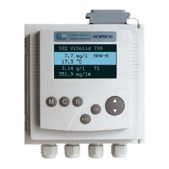
System 182-XT-4 Overview Overview Structure and function Fig. 1-1 DIQ/S 182-XT-4-PR Sensors Up to four main measured variables (e.g. pH, oxygen content, turbidity value...) together with their associated auxiliary measured variable (e.g. temperature) can be displayed and administrated with this measuring system. - Page 8 Overview System 182-XT-4 Relay outputs The relay outputs can be linked to sensors. Linked outputs can be used to monitor sensors and for the output of measured values. A relay output can be programmed as: a monitoring relay a limit monitor ...
-
Page 9: Behavior Of The System To A Power Failure
System 182-XT-4 Overview Behavior of the system to a power failure The system configuration is non volatile and is permanently retained. It consists of the following settings: – Sensor settings – Settings and links of the relay outputs – PROFIBUS settings –... - Page 10 Overview System 182-XT-4 1 - 4 ba76027e02 12/2014...
-
Page 11: Safety
System 182-XT-4 Safety Safety Safety information 2.1.1 Safety information in the operating manual This operating manual provides important information on the safe operation of the product. Read this operating manual thoroughly and make yourself familiar with the product before putting it into operation or working with it. -
Page 12: Safe Operation
Safety System 182-XT-4 Safe operation 2.2.1 Authorized use The authorized use of the System 182-XT-4 consists of its use in online analysis. Only the operation and running of the product according to the instructions and technical specifications given in this operating manual is authorized (see chapter 9 T ECHNICAL ). - Page 13 System 182-XT-4 Safety Special user The following installation activities may only be performed by a qualifications qualified electrician: Connection of the MIQ/PS power supply module to the power line (see MIQ/PS module manual). Connection of external, line voltage-carrying circuits to relay contacts (see module manual of the relay output module).
- Page 14 Safety System 182-XT-4 2 - 4 ba76027e02 12/2014...
-
Page 15: Installation
System 182-XT-4 Installation Installation How to connect the DIQ/S 182 XT-4-PR to the PROFIBUS master is described in detail in the chapter 7 PROFIBUS CONNECTION Scope of delivery The following parts are included in the scope of delivery of the DIQ/ S 182-XT-4-PR: ... -
Page 16: Basic Requirements For Installation
Installation System 182-XT-4 3.1.1 Basic requirements for installation 3.1.2 System planning Overview of planning Start steps Fundamentals of planning - Number and types of required sensors - Measuring locations to be designed - Distances - Infrastructure, process environment etc. Rough planning topology + layout ENSOR - Sum of all line lengths max. -
Page 17: Requirements Of The Measurement Location
System 182-XT-4 Installation 3.1.3 Requirements of the measurement location The measurement location must meet the environmental conditions specified in section 9.1. 3.1.4 Drawing up the power rating General information The System IQ S supplies all components with low voltage ENSOR as well as digital communication via a shielded 2-wire line. - Page 18 Installation System 182-XT-4 MIQ/JB MIQ/JBR MIQ/CR3 MIQ/C6 MIQ/R6 MIQ/IC2 + 2.2 W per connected WG 20 A2 power supply/isolator MIQ/CHV PLUS 1.0 x rel. turn-on duration * DIQ/CHV 0.8 x rel. turn-on duration * MIQ/Blue PS * In order to take the relative on-time into account, see following text Allowing for the relative Valves usually switch on periodically for a limited time and then require on-time in valves...
-
Page 19: Optimum Installation Of The Additional Miq Power Supply Module
System 182-XT-4 Installation Calculation example: Example configuration 1 Power Total power requirement [W] requirement P [W] (sum (component) of the components) ® + 1 VisoTurb 700 IQ ® + 1 ViSolid 700 IQ + 1.5 ® + 1 FDO 700 IQ + 0.7 ®... -
Page 20: Safety Requirements On The Electrical Installation
Installation System 182-XT-4 (example UV/VIS sensor). Safety requirements on the electrical installation Electrical equipment (e.g. motors, contactors, cables, lines, relays) must meet the following requirements: Conformity with national regulations (e.g. NEC, VDE and IEC) Suitability for the electrical conditions at the installation site –... - Page 21 System 182-XT-4 Installation integrated concept of the following protective measures is required: internal device-related protective measures and external protective measures of the installation environment. The internal device-related protective measures are already integrated in the YSI online measuring technology as so-called 'lightning protection' (see chapter 9 T ECHNICAL DATA The external protective measures of the installation environment can...
- Page 22 Installation System 182-XT-4 each outside location of the MIQ modules. Sun shields protect the electric field lines in the area of the MIQ module through an advantageous development of the electrical field lines in the area of the MIQ module and promote the dissipation of the surge via the mounting construction.
-
Page 23: Connecting System Components
System 182-XT-4 Installation Connecting system components 3.4.1 Connecting MIQ modules: General information You can connect the DIQ/S 182 XT-4 with MIQ modules without connecting cable (stacking). According to the same principle MIQ modules can also be connected with one another. Mounting direction Variant 1 - stack expansion MIQ Module... -
Page 24: Variant 1: Stack Expansion Forwards
Installation System 182-XT-4 NOTE For optimum stability only one MIQ module may be attached to the DIQ/S 182 XT-4-PR. In all MIQ modules in the System 182 XT-4 the terminator switch on the terminal strip must be set to "Off". ... - Page 25 System 182-XT-4 Installation Remove the covers from the drilled mounting holes (pos. 1 and 3 in Fig. 3-2). Remove the contact cover (pos. 2). Pull off the adhesive label (pos. 4). Mounting the contact DIQ/S 182 XT-4-PR base Fig. 3-3 Mounting the contact base (variant 1) Only use the plastic tapping screws supplied for attaching the contact base.
- Page 26 Installation System 182-XT-4 DIQ/S 182 XT-4-PR Premounting the ISO blind nuts Fig. 3-4 Premounting the ISO blind nuts (variant 1) Insert the cheese-head screws (pos. 8 in Fig. 3-4) with the plastic washers in the drilled mounting holes in the enclosure and loosely screw in the ISO blind nuts (pos.
-
Page 27: Variant 2: Stack Expansion Backwards
System 182-XT-4 Installation MIQ module DIQ/S 182 XT-4-PR Fig. 3-6 Closing the enclosure (variant 1) Attach the prepared DIQ/S 182-XT-4-PR to the cover of the MIQ module. At the same time, ensure that the two clips on the DIQ/S 182-XT-4-PR click into place in the lid of the MIQ module. - Page 28 Installation System 182-XT-4 Remove the covers from the drilled mounting holes (pos. 1 and 3 in Fig. 3-7). Remove the contact cover (pos. 2). Pull off the adhesive label (pos. 4). On the MIQ module, remove the two countersunk screws (pos. 5) and swing open the module lid.
- Page 29 System 182-XT-4 Installation Premounting the ISO MIQ module blind nuts Fig. 3-9 Premounting the ISO blind nuts (variant 2) Insert the cheese-head screws (pos. 8 in Fig. 3-9) with the plastic washers in the drilled mounting holes in the module lid and loosely screw in the ISO blind nuts (pos.
-
Page 30: Distributed Mounting
Installation System 182-XT-4 DIQ/S 182 XT-4-PR MIQ module Fig. 3-11 Closing the enclosure (variant 2) Attach the prepared MIQ module to the back of the DIQ/S 182- XT-4-PR. At the same time, ensure that the two clips on the DIQ/S 182-XT-4-PR click into place in the lid of the MIQ module. - Page 31 System 182-XT-4 Installation connections are of equal value in the system. NOTE The IQ S cable may only be connected to the SENSORNET ENSOR connections. No wires of the cable may be connected with an external electrical potential. Otherwise, malfunctions could occur. General installation Pay attention to the following points when connecting components via instructions...
- Page 32 Installation System 182-XT-4 approx. 45 mm SNCIQ approx. 35 mm approx. 45 mm SNCIQ/UG Fig. 3-12 Prepared cable end Connecting the cables The SNCIQ and SNCIQ/UG cables are connected to the terminal strip in the same way as the SACIQ sensor connection cable (see section 3.4.5): Open the enclosure of the DIQ/S 182-XT-4-PR or the MIQ module.
- Page 33 System 182-XT-4 Installation SENSORNET 1 SENSORNET 2 SNCIQ SACIQ SNCIQ/UG Fig. 3-13 Connect cable (example: rear terminal strip) Screw a cable gland (pos. 1 in Fig. 3-13) with the sealing ring (pos. 2) into the enclosure. Loosen the coupling ring (pos. 3 in Fig. 3-13). Feed the cable through the cable gland into the enclosure.
-
Page 34: Connecting Iq Sensors
Installation System 182-XT-4 3.4.5 Connecting IQ sensors Sensors can be connected to all free SENSORNET connectors in the System 182 XT-4. The DIQ/S 182-XT-4-PR has three SENSORNET connections. If no more free SENSORNET connections are available, other sensors with the DIQ/JB branching module can be connected (see section 3.6 and installation examples in section 3.11). - Page 35 System 182-XT-4 Installation Then, screw the coupling ring (2) of the IQ sensor connection cable on the IQ sensor up to the stop. SACIQ Fig. 3-14 Connecting the SACIQ cable with the IQ sensor For further instructions on the mounting of IQ sensors at the application location, please see the respective manuals (immersion depths, etc.).
-
Page 36: Onsite Installation Of Diq/S 182-Xt-4-Pr And Miq Modules
Installation System 182-XT-4 Onsite installation of DIQ/S 182-XT-4-PR and MIQ modules 3.5.1 General information The DIQ/S 182-XT-4-PR and the DIQ and MIQ modules have a comprehensive program of mounting accessories, which can be used to adapt the installation to the most varied requirements. NOTE Components installed outside must always be protected by a sun shield against the effects of the weather (snow, ice and direct solar ra... -
Page 37: Mounting On A Mounting Stand With The Ssh/Iq Sun Shield
System 182-XT-4 Installation chapters. MIQ modules are mounted in the same way. 3.5.2 Mounting on a mounting stand with the SSH/IQ sun shield SSH/IQ sun shield (see chapter 11 A Materials required CCESSORIES AND OPTIONS 4 mm set screw wrench Tools ... - Page 38 Installation System 182-XT-4 Premounting the ISO blind nuts Fig. 3-16 Mounting the sun shield: Premounting the ISO blind nuts Remove the two countersunk screws (pos. 5 in Fig. 3-16) and swing open the lid. Insert the cheese-head screws (pos. 6 in Fig. 3-16) with the plastic washers in the drilled mounting holes and loosely screw in the ISO blind nuts (pos.
- Page 39 System 182-XT-4 Installation Position the DIQ/S 182-XT-4-PR on the sun shield and fix it into place with the two screws (pos. 6 in Fig. 3-16). Close the lid and fix it with the two countersunk screws (pos. 5 in Fig. 3-16). PROFIBUS cable route Guide the PROFIBUS cable in the sun shield recess behind the Universal Transmitter to the top of the housing...
-
Page 40: Panel Mounting
Installation System 182-XT-4 3.5.3 Panel mounting PMS/IQ kit for panel mounting (see chapter 11 A Materials required CCESSORIES AND OPTIONS 3 mm set screw wrench (contained in the panel installation kit). Tools Switch panel aperture Maximum thickness 3 mm 34.5 Fig. - Page 41 System 182-XT-4 Installation e la ie r a r r n t in t a c ll c t a c s t a d in Fig. 3-20 Mounting DIQ/S 182 Universal Transmitter in switch panel Slightly unscrew the screws (pos. 2 and 3) of the two angle brackets (pos.
-
Page 42: Top Hat Rail Mounting
Installation System 182-XT-4 3.5.4 Top hat rail mounting THS/IQ kit for top hat rail mounting (see chapter 11 A Materials required CCESSORIES AND OPTIONS Phillips screwdriver. Tools Mounting the DIQ/S 182 XT-4-PR on a top hat rail e la ie r a r r n t in... -
Page 43: Using Diq Modules (Accessories)
System 182-XT-4 Installation Using DIQ modules (accessories) The various application possibilities of the DIQ modules are shown by means of examples in section 3.11. 3.6.1 DIQ/JB The DIQ/JB module is a passive branching module and can be used for the following purposes: ... -
Page 44: Installation Of The Diq Modules
Installation System 182-XT-4 Fig. 3-23 DIQ/CHV open. 3.6.3 Installation of the DIQ modules The DIQ module enclosure is designed like a commercial connection socket and can be mounted directly on a wall. For mounting on a YSI mounting stand, YSI provides the MS/DIQ mounting set. It contains a pipe clip for the mounting stand and provides enough space for two DIQ modules. -
Page 45: Electrical Connections: General Instructions
System 182-XT-4 Installation Electrical connections: General instructions Cable glands All electric cables are fed from below via prepared openings in the enclosure of the DIQ/S 182-XT-4-PR and the MIQ modules. Cable glands with different clamping ranges are included with the DIQ/S 182- XT-4-PR to provide sealing between the cable and enclosure as well as for strain relief. -
Page 46: Connecting The Voltage Supply
Installation System 182-XT-4 General installation Observe the following points when attaching connecting wires to the instructions terminal strip Shorten all wires to be used to the length required for the installation Always fit all the ends of the wires with wire end sleeves before connecting them to the terminal strip ... - Page 47 System 182-XT-4 Installation – marked as an interrupt facility for the DIQ/S 182-XT-4-PR. After it has been installed, the DIQ/S 182-XT-4-PR may only be opened if the mains voltage has been switched off beforehand. Wire end sleeves, suitable for the power line, with suitable crimping Materials required tool ...
- Page 48 Installation System 182-XT-4 Connecting the power Open the enclosure of the DIQ/S 182 XT-4-PR (front terminal line strip). Fig. 3-26 Inserting the supply line. Screw a cable gland (pos. 1 in Fig. 3-26) with sealing ring (pos. 2) into the enclosure below the power supply connection. Loosen the coupling ring (pos.
- Page 49 System 182-XT-4 Installation Terminal labeling: 100... 240V AC MAINS Fig. 3-27 Line power connection. The complete assignment of the terminal strip is shown in section 3.12. Connect phases L and N to the terminal strip. Make sure that the cable assignment agrees with the specification on the terminal label under the terminal strip.
-
Page 50: Diq/S 182-Xt-4-Pr/24V (24 V Version)
Installation System 182-XT-4 3.8.2 DIQ/S 182-XT-4-PR/24V (24 V version) WARNING If the 24 V AC/DC supply is incorrectly connected, it may represent a danger to life from electric shock. Pay attention to the following points during installation: The DIQ/S 182-XT-4-PR must only be connected by a qualified electrician. - Page 51 System 182-XT-4 Installation Fig. 3-28 Prepared 24 V AC/DC line. Connecting the 24 V AC/ Open the enclosure of the DIQ/S 182 XT-4-PR (front terminal DC line strip). Fig. 3-29 Inserting the 24V AC/DC line Screw a cable gland (pos. 1 in Fig. 3-29) with sealing ring (pos. 2) into the enclosure below the 24 V AC/DC connection.
- Page 52 Installation System 182-XT-4 Terminal labeling: 24V AC DC INPUT POWER Fig. 3-30 24 V AC/DC connection. The complete assignment of the terminal strip is shown in section 3.12. Connect wires 1 and 2 to the terminal strip. Make sure that the cable assignment agrees with the specification on the terminal label under the terminal strip.
-
Page 53: Connection To The Relay Outputs
System 182-XT-4 Installation Connection to the relay outputs 3.9.1 General installation instructions WARNING If external electrical circuits that are subject to the danger of physical contact are incorrectly connected to the relay contacts, there may be a danger of life threatening electric shock. Electrical circuits are regarded to be subject to the danger of physical contact when there are voltages higher than the Safety Extra Low Voltage (SELV). - Page 54 Installation System 182-XT-4 Connecting lines to the Open the enclosure of the DIQ/S 182 XT-4-PR. terminal strip Fig. 3-31 Feeding in the lines (example: front terminal strip) Screw a cable gland (pos. 1 in Fig. 3-31) with the sealing ring (pos.
-
Page 55: Usage Of The Auxiliary Voltage
System 182-XT-4 Installation Close the enclosure of the DIQ/S 182 XT-4-PR. 3.9.2 Usage of the auxiliary voltage The DIQ/S 182 XT-4-PR has a 24 V output (designation, HILFSSPANNUNG or AUXILIARY VOLTAGE on the terminal strip). You can use this auxiliary voltage for the relay-controlled opening of the valve in a DIQ/CHV valve module for the compressed air-driven sensor cleaning function. - Page 56 Installation System 182-XT-4 Divider Relay connection Auxiliary voltage Bridge Valve control line Installation examples with one and two sensors with compressed air cleaning can be found in section 3.11. 3 - 42 ba76027e02 12/2014...
-
Page 57: Commissioning
System 182-XT-4 Installation 3.10 Commissioning Start checklist and Before starting the system, carry out the system check using the system start following checklist. Always carry out the check before the initial commissioning before any further commissioning if the system has been previously extended or modified. -
Page 58: Installation Examples
Installation System 182-XT-4 3.11 Installation examples 3.11.1 Compressed air cleaning of two sensors Maximum cable length SNCIQ(/UG) plus SACIQ = 250 m DIQ/S 182 XT-4-PR SACIQ Valve control line 1 Valve control line 2 DIQ/CHV 2 DIQ/CHV 1 SACIQ SACIQ Sensor 2 Sensor 1 Connection scheme of... - Page 59 System 182-XT-4 Installation sensors is carried out with the same settings. WARNING In this configuration, the free switching contact (here: R3) may be used to switch SELV voltages only. WARNING No free wires must be allowed to project into the enclosure. Otherwise, there is a danger that areas safe to contact could come into contact with dangerous voltages.
- Page 60 Installation System 182-XT-4 Shield / Filler stranded wire Connection scheme of the DIQ/JB SNCIQ(/UG) Terminal strip DIQ/JB green X6 X7 green green SACIQ SACIQ black black Sensor 2 Sensor 1 3 - 46 ba76027e02 12/2014...
-
Page 61: Connection Of A Sensor That Is Located At A Distance
System 182-XT-4 Installation 3.11.2 Connection of a sensor that is located at a distance (without compressed air cleaning) DIQ/S 182 XT-4-PR Maximum cable length SNCIQ(/UG) plus SACIQ = 250 m SNCIQ(/UG) DIQ/JB SNCIQ(/UG) SACIQ SACIQ Sensor ba76027e02 12/2014 3 - 47... - Page 62 Installation System 182-XT-4 Shield / Filler stranded wire Connection scheme of SNCIQ(/UG) DIQ/JB green Terminal strip DIQ/JB green SACIQ black 3 - 48 ba76027e02 12/2014...
-
Page 63: Figures Of The Terminal Strips
System 182-XT-4 Installation 3.12 Figures of the terminal strips DIQ/S 182-XT-4-PR, ≤ ≤ ≤ 240V AC 240V AC 240V AC ≤ ≤ ≤ 2A AC 2A AC 2A AC AUXILIARY front terminal strip VOLTAGE 100... 240V AC SENSORNET 2 SENSORNET 1 MAINS AUXILIARY DIQ/S 182-XT-4-PR/24V,... - Page 64 Installation System 182-XT-4 3 - 50 ba76027e02 12/2014...
-
Page 65: Operation
System 182-XT-4 Operation Operation Operating elements Display Toggle switch Key pad Fig. 4-1 Operating elements of the DIQ/S 182 XT-4-PR Functions Function Switches directly to the measured value display from all operating situations Starts calibration of the sensor selected in the measured value display Opens the SETTINGS menu in the measured value and status display... -
Page 66: Measured Value And Status Display
Operation System 182-XT-4 Measured value and status display key switches to the last selected measured value and status display from any operating situation. Entries that are not completed are ignored while doing so. Pressing once again cyclically switches between further display options. - Page 67 System 182-XT-4 Operation Select the PROPERTIES menu with . This menu can be used to put sensors in the maintenance condition and prompt for important data (calibration data, error messages, operating states, software versions etc.). Open the SETTINGS menu with Special The following displays inform you of special states of the sensors sensor conditions...
-
Page 68: Working With The Settings Menu
Operation System 182-XT-4 Working with the SETTINGS menu All settings in the SETTINGS menu can be protected by a password against unauthorized changing. For more detailed information on password protection, see section 4.6. 4.3.1 Selection menus Pressing switches from the measured value display to the SETTINGS menu (main menu). -
Page 69: Setting Tables
System 182-XT-4 Operation 4.3.2 Setting tables The actual settings are made in the setting tables. Each setting is represented by two lines together. The name of the setting appears in the upper line on the left side of the display. The corresponding value is in the line below on the right side. -
Page 70: Entry Mode
Operation System 182-XT-4 4.3.3 Entry mode In the entry mode you can change individual values or enter a character string. Depending on the value type, change a value as follows Fixed values of a selection list (e.g. sensor measuring ranges): This is the most frequent form of an entry. - Page 71 System 182-XT-4 Operation Numerals: Entering numerals is made in the same way as entering characters. The following numerals can be entered: 0..9-. Entering" -" or "." is only allowed where it makes sense, e.g. "-" at the first position only. Save and quit On principle, all settings made in the entry mode are only taken over after selecting the Save and quit item in the relevant setting table and...
-
Page 72: Properties Menu
Operation System 182-XT-4 PROPERTIES menu 4.4.1 Overview Pressing switches from the measured value display to the PROPERTIES menu. In the PROPERTIES menu, you can prompt calibration data and various information on system components. Moreover, you can switch the maintenance condition of a sensor on and off. Fig. -
Page 73: Maintenance Condition
System 182-XT-4 Operation 4.4.2 Maintenance condition When an IQ sensor is calibrated, cleaned, serviced or repaired, the maintenance condition for the relevant IQ sensor should always be switched on. In the maintenance condition apart from the measured value display, the system does not react to the current measured value or the condition of the selected IQ sensor ... - Page 74 Operation System 182-XT-4 Recommended Switch on the maintenance condition for the IQ sensor. The proceeding for cleaning, measured value display flashes. maintenance and repair Pull the sensor out of the sample. Carry out the cleaning, maintenance or repair (removal and replacement) of the sensor.
-
Page 75: Sensor Status Sxx
System 182-XT-4 Operation 4.4.3 Sensor status Sxx In the SENSOR STATUS Sxx menu you can prompt the following information on a sensor: Type and series number Software status Error and info messages ("log book") Data of the last calibration (only for sensors that can be calibrated) figure 4-8 SENSOR STATUS Sxx Log book The log book is a list of messages related to a sensor. - Page 76 Operation System 182-XT-4 Calibration data You can view the data of the last calibration under the Cal menu item. Sensors that have not yet been calibrated do not have this menu item. The symbol in the Cal line quotes the validity state: = valid = invalid The content and form of the calibration data depend on the sensor type.
- Page 77 System 182-XT-4 Operation Type number Structure of the message code Type Category figure 4-10Message code Pos. Information Explanation Info message (I) Category Error message (E) Calibration (C) Type Installation and commissioning (I) Instructions for service and repair (S) ...
- Page 78 Operation System 182-XT-4 Select the Log... menu item and press The log book is displayed. Highlight the message to be acknowledged and press . The detailed message text is displayed. Scroll through the text with the toggle switch Press . Thus you acknowledge the message (). Press once again.
-
Page 79: Calibration Of Sensors
System 182-XT-4 Operation Calibration of sensors Sensors can be protected by a password against unauthorized calibration. For more detailed information on password protection, see section 4.6. General proceeding Switch to the measured value display with Select the sensor to be calibrated with (in the single display, the sensor being displayed is always selected at the same time). - Page 80 Operation System 182-XT-4 Confirm the calibration data with . Calibration is completed with this. The following display message describes the further steps to put the sensor into operation again. Putting the sensor into Confirm with . The display returns to the measured value operation after display (the measured value flashes as the sensor is still in the calibrating...
-
Page 81: Passwords
System 182-XT-4 Operation Passwords You can assign and activate two passwords for the System 182-XT-4. Settings password protects all settings in the SETTINGS menu. If the password is active, all settings can be viewed but not changed. The password prompt appears on leaving a setting table with the Save and quit command. - Page 82 Operation System 182-XT-4 4 - 18 ba76027e02 12/2014...
-
Page 83: The Settings Menu
System 182-XT-4 The SETTINGS menu The SETTINGS menu Overview of the SETTINGS menu Pressing switches from the measured value display to the SETTINGS menu (main menu). To view these menu items, scroll down with figure 5-1 Submenus in the SETTINGS menu The individual submenus are described in the following paragraphs. -
Page 84: Sensor S01 To S04
The SETTINGS menu System 182-XT-4 If the selected system language is not available in a sensor, all displays of this sensor appear in the standard language, English. To activate the selected system language for this component, a software update of the component is required. -
Page 85: Relay Output R1/R2/R3
System 182-XT-4 The SETTINGS menu To accept all settings, highlight the Save and quit menu item at the lower end of the setting table and press . If you exit the setting table via /Quit or the Quit menu item, all changes are ignored. Inactive sensor datasets An inactive dataset for an IQ sensor arises if the DIQ/S 182-XT-4-PR receives no signals from an IQ sensor that is already registered. -
Page 86: Profibus Config
The SETTINGS menu System 182-XT-4 options are described in detail in the chapter 6 R menu. ELAY OUTPUTS PROFIBUS config. You can set the PROFIBUS address in this menu (see operating manual "IQ S Field bus linking"). ENSOR System The settings in the SYSTEM menu comprise: ... - Page 87 System 182-XT-4 The SETTINGS menu Settings Sensor settings Sensor dependent (see settings tables in the respective sensor operating manual). Note: Calibration of the sensor is stored in the sensor and is retained when the system configuration is reset. Relay outputs No function, all links are erased PROFIBUS address ba76027e02...
- Page 88 The SETTINGS menu System 182-XT-4 5 - 6 ba76027e02 12/2014...
-
Page 89: Relay Outputs
System 182-XT-4 Relay outputs Relay outputs Outputs of the system 182 XT-4 The DIQ/S 182-XT-4-PR has three relay outputs. System monitoring Functions for relay outputs Sensor monitoring Limit indicator Frequency output Pulse-width output Sensor controlled ... -
Page 90: Linking And Adjusting: General Procedures
Relay outputs System 182-XT-4 Linking and adjusting: general procedures 6.2.1 linking outputs Linking options You have the following options of linking relay outputs: Sensor Sxx The output is linked with sensor 0x Sensor S01&S02 The output is linked to both sensors S01 and S02. ... -
Page 91: Deleting A Link With An Output
System 182-XT-4 Relay outputs 6.2.2 Deleting a link with an output If a link is no longer required, it can be erased. Procedure: Open the SETTINGS menu with Erasing a link Using , select and confirm the Relay output Rx menu item (corresponding to sensor 1, 2 or 3). -
Page 92: Setting Outputs
Relay outputs System 182-XT-4 6.2.3 Setting outputs Procedure: Open the SETTINGS menu with Setting an output Using , select and confirm the Relay output Rx menu item (corresponding to sensor 1, 2 or 3). Confirm the selection Set output with The setting table of the output is displayed. -
Page 93: Basic Information On Relay Functions
System 182-XT-4 Relay outputs Basic information on relay functions This chapter describes general basic information concerning the following relay functions: Monitoring (see section 6.3.1) Limit indicator (see section 6.3.2) Proportional output (see section 6.3.3) 6.3.1 Monitoring When using a relay for monitoring, a relay action (Open, Close) occurs when certain states occur. - Page 94 Relay outputs System 182-XT-4 Monitoring limiting Measured values using one or two value relays Relay 1 Hysteresis UL Hysteresis LL Relay 2 Time Fig. 6-1 Switching points for relays with the function of a limit indicator Upper limit value (relay 1) exceeded Selected switching delay t1 for relay 1 expired Relay 1 switches Hysteresis for upper limiting value (relay 1) undercut...
-
Page 95: Proportional Output
System 182-XT-4 Relay outputs 6.3.3 Proportional output In the case of proportional output, a relay switches cyclically on and off in a defined measured value range (proportional range). At the same time, the relay switches with a: duration of operation that corresponds to the measured value (pulse-width output, see page 6-9) or ... - Page 96 Relay outputs System 182-XT-4 Switching frequency f or Output with one relay Pulse width Proportional band Measured value Fig. 6-2 Output with one relay Output with two relays Switching frequency f or Pulse width Proportional bands Relay 1 and 2 Measured value Relay 1 Relay 2...
- Page 97 System 182-XT-4 Relay outputs Pulse width output The output via the pulse width is used, e.g. for controlling valves. Pulse-width regulation changes the duration of operation (ton) of the output signal. Depending on the position of the measured value in the proportional range, the relay is operated for a longer or shorter period.
- Page 98 Relay outputs System 182-XT-4 Frequency output Switching frequency output is used, e.g. for controlling dosing pumps. In contrast to the pulse-width output, the pulse width is not modulated with the frequency output but the switching frequency of the output signal. Depending on the position of the measured value in the proportional range, the relay is switched more often or less often.
- Page 99 System 182-XT-4 Relay outputs Characteristic curves Through the selection of the Start value and End value, the proportional output can be operated with a positive or negative characteristic curve. Positive characteristic curve: Select the End value to be greater than the Start value. The turn-on duration or frequency increases with an increasing measured value (see page 6-12).
- Page 100 Relay outputs System 182-XT-4 Positive characteristic The proportional output range begins above the initial value. If the curve proportional range is undercut or exceeded, the selected behavior comes into force. Pulse width v [%] Cycle duration T Of f Proportional band Time Measured value 2...
- Page 101 System 182-XT-4 Relay outputs Negative characteristic The proportional output range begins below the initial value. If the curve proportional range is undercut or exceeded, the selected behavior comes into force. Fig. 6-10 Pulse width output Switching frequency f [1/min] Maximum switching frequency 50 % of maximum switching frequency...
-
Page 102: Setting Table For Relays
Relay outputs System 182-XT-4 Setting table for relays 6.4.1 Functions and settings To set a relay, its function has to be selected first. Then the relevant setting table is displayed: Relay function and Function Setting table relevant setting tables No function The relay output is not used. -
Page 103: System Monitoring
System 182-XT-4 Relay outputs 6.4.2 System monitoring Function The System monitoring enables the monitoring of system errors. To set up the System monitoring function for a relay output, you have to select the System option when linking the relay output (see section 6.2.1). -
Page 104: Sensor Monitoring
Relay outputs System 182-XT-4 6.4.3 Sensor monitoring Function The Sensor monitoring function enables the monitoring of sensor errors and the maintenance condition. In order to set up the Sensor monitoring function for a relay output, the relay output must be linked with a sensor (see section 6.2.1). Settings Setting Selection... -
Page 105: Limit Indicator
System 182-XT-4 Relay outputs 6.4.4 Limit indicator Function The characteristic of the limit indicator is laid down in the Limit value UL, Limit value LL, Hysteresis UL and Hysteresis LL settings. The fundamentals of the function are described in the introductory chapter (see section 6.3.2). -
Page 106: Frequency Output
Relay outputs System 182-XT-4 6.4.5 Frequency output Function The characteristic of the frequency output is laid down in the Start value, End value, Frequency (f) min. and Frequency (f) max. settings. The fundamentals of the function are described in the introductory chapter (see section 6.3.3). -
Page 107: Pulse-Width Output
System 182-XT-4 Relay outputs 6.4.6 Pulse-width output Function The characteristic of the pulse width output is laid down in the Start value, End value, Pulse width (v) min. and Pulse width (v) max. settings. The fundamentals of the function are described in the introductory chapter (see section 6.3.3). -
Page 108: Sensor Controlled
Relay outputs System 182-XT-4 6.4.7 Sensor controlled With the Sensor controlled function, the relay is controlled by a linked sensor. Requirement Sensor that transmits signals to trigger a cleaning cycle, e.g. UV/VIS sensor Settings Setting Selection/Values Explanation Pulse length Automatic The duration of the air cleaning process is programmed in the... - Page 109 System 182-XT-4 Relay outputs 6.4.8 Cleaning Function The Cleaning function enables the time controlled automatic start of the sensor cleaning function with the aid of a relay of the DIQ/S 182-XT-4- PR. The relay controls the DIQ/CHV valve module and switches the compressed air for the CH sensor cleaning head on or off.
-
Page 110: Cleaning
Relay outputs System 182-XT-4 Settings Setting Selection/Values Explanation Reference time (h) 0 ... 23 h Time at which a cleaning cycle is Reference time 0 ... 60 min started. Further (min) cleaning cycles will be performed at the times specified by the cleaning interval. - Page 111 System 182-XT-4 Relay outputs Example Setting Result Reference time (h): Reference time: 12:00 hours Reference time This specifies the following (min): Hours (h) start times: Interval unit: 04:00, 12:00 and 20:00 hours Cleaning interval: t1a t1b relay condition closed open 00:00 04:00 12:00...
-
Page 112: Manual Control
Relay outputs System 182-XT-4 Canceling the cleaning A running cleaning cycle is canceled: Automatically – if the sensor switches to the inactive condition during the cleaning cycle Manually – By pressing – By switching on the maintenance condition Each time the cleaning cycle is canceled, the relay opens immediately. -
Page 113: Behavior Of Linked Relay Outputs
System 182-XT-4 Relay outputs Behavior of linked relay outputs 6.5.1 Behavior in case of error For linked relay outputs, you can specify the behavior of the outputs in case of errors. Depending on the use of the output, the behavior in case of errors is set in the following menus: Output Menu... - Page 114 Relay outputs System 182-XT-4 6 - 26 ba76027e02 12/2014...
-
Page 115: Maintenance And Cleaning
System 182-XT-4 Maintenance and cleaning Maintenance and cleaning Maintenance Maintenance activities Component Maintenance IQ sensors Depending on the type of sensor (see the component operating manual of the sensor) DIQ/S 182-XT-4-PR, No maintenance required DIQ modules, MIQ modules Cleaning DIQ/S 182-XT-4-PR, Clean components mounted in the open of gross contamination as DIQ modules, necessary. - Page 116 Maintenance and cleaning System 182-XT-4 7 - 2 ba76027e02 12/2014...
-
Page 117: What To Do If
System 182-XT-4 What to do if ... What to do if ... Information on errors Log book The 182 XT-4 system performs a comprehensive cyclical self test during operation. While doing so, the system identifies all states that deviate from normal operation and enters corresponding messages in the log book (information or error message). -
Page 118: Replacing System Components
What to do if ... System 182-XT-4 The selected system Cause Remedy language was not – A system language was selected – Contact YSI, activated for a sensor that is not available in the a software update is sensor. required for the respective The English language was components activated instead of the selected... -
Page 119: Adding And Replacing Iq Sensors
System 182-XT-4 What to do if ... 8.3.2 Adding and replacing IQ sensors Inactive datasets of If an IQ sensor is removed from the system, its settings remains stored IQ sensors in the DIQ/S 182-XT-4-PR as an inactive dataset. A dataset contains the following information: ... - Page 120 What to do if ... System 182-XT-4 Case 2: The type of sensor is identical Operator intervention is required with the type of sensor in an here. The connected IQ sensor inactive dataset (or several can: inactive datasets), but the serial –...
- Page 121 System 182-XT-4 What to do if ... Operating sequence in Connect the IQ sensor. case 2 Change to the measured value display with . The component database is updated. The following display appears (example): Select the required option with and confirm with –...
- Page 122 What to do if ... System 182-XT-4 8 - 6 ba76027e02 12/2014...
-
Page 123: Technical Data
System 182-XT-4 Technical data Technical data DIQ/S 182-XT-4-PR Dimensions Front view: Side view: 144.0 143.0 23.0 43.0 11.0 Rear view: 16.5 115.0 70.0 Stack mounting: 137.0 Fig. 9-1 Dimension drawing of the DIQ/S 182-XT-4-PR (dimensions in mm) Test marks ba76027e02 12/2014 9 - 1... - Page 124 Technical data System 182-XT-4 Mechanical Enclosure material Polycarbonate with 20 % glass fiber construction Weight Approx. 0.7 kg Type of protection – IP 66 – corresponds to NEMA 4X The DIQ/S 182-XT-4-PR is not suitable for conduit connection Ambient conditions Temperature Operation - 20 °C ...
- Page 125 System 182-XT-4 Technical data Electrical data Supply Nominal voltage: 24 V AC/DC ± 10 % DIQ/S 182-XT-4-PR/24V protective low voltage (24 V AD/DC version) SELV (Safety Extra Low Voltage) AC frequency: 50/60 Hz according to DIN IEC 60038 Connection: 2 pin Line cross-section of connections: Europe:1.5 ...
- Page 126 Technical data System 182-XT-4 Relay Output Galvanically separated (3 x) Max. switching voltage Front terminal strip: 240 VAC or 24 VDC Rear terminal strip: 250 VAC or 24 VDC Max. switching current Front terminal strip: 2 A (AC and DC) Rear terminal strip: 5 A (AC and DC) Fuse rating on the...
- Page 127 System 182-XT-4 Technical data EMC product and EN 61326 EMC requirements for electrical resources system characteristics for control technology and laboratory use – Resources for industrial areas, intended for indispensable operation – Interference emission limits for resources of class B System lightning Extended protective characteristics as protection...
-
Page 128: Miq Modules
Technical data System 182-XT-4 MIQ modules Technical data on special MIQ modules are given in the respective operating manuals. Dimensions 144,0 52,2 Front view: Side view: 115,0 11,0 70,0 16,5 Rear view Stack mounting: Fig. 9-2 Dimension drawing of MIQ module (dimensions in mm) 9 - 6 ba76027e02 12/2014... - Page 129 System 182-XT-4 Technical data Mechanical Maximum number of 1 plus DIQ/S 182-XT-4-PR construction MIQ modules in a module stack Enclosure material Polycarbonate with 20 % glass fiber Weight Approx. 0.5 kg (type-dependent) Type of protection – IP 66 – In accordance with NEMA 4X MIQ modules are not suitable for conduit connection Terminal connections...
-
Page 130: Diq/Jb
Technical data System 182-XT-4 DIQ/JB Dimensions DIQ/JB Fig. 9-3 Dimension drawing of DIQ/JB (dimensions in mm) Mechanical Enclosure material Polystyrene construction Weight Approx. 0.2 kg Type of protection IP 66 Electrical connections (7 passive, potential free terminals for line extension or branching) Terminals Terminal type Screw-type terminal strip... -
Page 131: Diq/Chv
System 182-XT-4 Technical data DIQ/CHV Dimensions DIQ/CHV Fig. 9-4 Dimension drawing of DIQ/CHV (dimensions in mm) Mechanical Enclosure material Polystyrene construction Weight Approx. 0.3 kg Type of protection IP 66 1 x valve switching contact Electrical connections 4 x potential-free terminals to connect interface lines Terminal strip inside the enclosure: (AUXILIARY) VALVE... - Page 132 Technical data System 182-XT-4 Valve circuits Switching voltage Approx. 22 V Max. switching current Approx. 40 mA NOTE The valve may only be operated with the auxiliary voltage of the DIQ/ S 182-XT-4-PR. Compressed air Required air quality Dry, free of dust and oil Operating pressure Max.
-
Page 133: Space Required By Mounted Components
System 182-XT-4 Technical data Space required by mounted components Wall mounting and top hat rail mounting Wall mounting top hat rail mounting Space required for screwdriver Fig. 9-5 Space required for wall and top hat rail mounting: (dimensions in mm) Panel mounting Panel mounting Space required... - Page 134 Technical data System 182-XT-4 9 - 12 ba76027e02 12/2014...
- Page 135 System 182-XT-4 ba76027e02 12/2014...
-
Page 136: Contact Information
Contact Information System 182-XT-4 Contact Information 10.1 Ordering & Technical Support Telephone: (800) 897-4151 (937) 767-7241 Monday through Friday, 8:00 AM to 5:00 PM ET Fax: (937) 767-1058 Email: environmental@ysi.com Mail: YSI Incorporated 1725 Brannum Lane Yellow Springs, OH 45387 Internet: www.ysi.com When placing an order please have the following information available:... -
Page 137: Accessories And Options
System 182-XT-4 Accessories and options Accessories and options Description Model Order no. IQ S cable - please specify the SNCIQ 480 046Y ENSOR required length in m with your order SNCIQ/UG 480 047Y IQ sensor connection cable – 1.5 m SACIQ-1.5 480 040Y –... - Page 138 Accessories and options System 182-XT-4 11 - 2 ba76027e02 12/2014...
-
Page 139: Index
System 182-XT-4 Index Index Air pressure ..........5-4 Inactive dataset ........5-3, 8-3 Altitude ............5-4 Info symbol ........4-3, 4-11 Ambient conditions ........9-2 Auxiliary voltage Terminal strip ........3-49 Key functions ..........4-1 Usage ..........3-41 Language ..........5-1 Calibration Setting .......... - Page 140 Index System 182-XT-4 Toggle switch ..........4-1 Types of installation .........3-22 Password Calibration .........4-17 Settings ..........4-17 Power failure ..........1-3 Power rating ..........3-3 Power requirement ........3-3 Pulse width output (relay) ......6-19 Relay Behavior in case of error ....6-25 Behavior in non-operative condition ..6-25 Display of states ........4-2 Functions and settings .......6-14 Terminal strip ........3-49...
-
Page 141: Appendix (Store Separately If Required)
System 182-XT-4 Appendix (store separately if required) Appendix (store separately if required) 13.1 Forgotten the password? Proceeding: Open the SETTINGS menu with prompting the password Depending on the password to be prompted, use to select and confirm the menu item, Settings Calibrate . - Page 142 Appendix (store separately if required) System 182-XT-4 13 - 2 ba76027e02 12/2014...
- Page 144 150 countries, we have strong, long-standing relationships with customers who know us for our powerful combination of leading product brands and applications expertise, backed by a legacy of innovation. For more information on how Xylem can help you, go to www.xyleminc.com 1725 Brannum Lane Yellow Springs, OH 45387 Tel: +1 937-767-7241;...
Need help?
Do you have a question about the YSI DIQ/S 182-XT-4-PR and is the answer not in the manual?
Questions and answers