
Related Manuals for Xylem YSI Alyza IQ PO4


Summary of Contents for Xylem YSI Alyza IQ PO4
- Page 1 OPERATIONS MANUAL ba76201e03 05/2020 Alyza IQ PO4 1- AND 2-CHANNEL MEASURING SYSTEMS FOR ONLINE DETERMINATION OF ORTHO-PHOSPHATE IN AQUEOUS SAMPLES...
- Page 2 Alyza IQ PO4 For the most recent version of the manual, please visit www.ysi.com. Contact 1725 Brannum Lane Yellow Springs, OH 45387 USA Tel: +1 937-767-7241 800-765-4974 Email: info@ysi.com Internet: www.ysi.com © Copyright 2020 Xylem Inc. ba76201e03 05/2020...
-
Page 3: Table Of Contents
Alyza IQ PO4 Contents Contents Overview ........7 How to use this component operating manual . - Page 4 Contents IQ S Alyza IQ ENSOR 3.3.7 Installation on a wall ....... 40 3.3.8 Removing the transport protection of the measuring unit .
- Page 5 IQ S Alyza IQ Contents ENSOR 4.5.4 More information on the Alyza IQ (Tab Info) ... . 96 Transferring information to a USB memory device via the Alyza IQ 4.6.1 Transferring to a USB memory device a selection of important operating data .
- Page 6 Contents IQ S Alyza IQ ENSOR 5.12.2 Preparing the Alyza IQ for transport or storage ..149 5.13 Recommissioning the Alyza IQ ......151 What to do if ...
-
Page 7: Overview
Alyza IQ PO4 Overview Overview How to use this component operating manual Structure of the IQ S ENSOR operating manual IQ S System operating manual (ring binder) ENSOR Operating manuals for components and options (e.g. field bus) figure 1-1 Structure of the IQ S operating manual ENSOR The IQ S... -
Page 8: Metrological Basics Po4-P, Po4
Overview Alyza IQ PO4 Metrological basics PO4-P, PO4 Phosphate The salts of the phosphoric acid are called phosphates. With simple phosphoric acid (orthophosphoric acid, H ) this is orthophosphate (anion PO Measuring method The Alyza IQ PO4 analyzer measures the concentration of orthophosphate in an aqueous solution with the aid of the vanadate molybdate method (yellow method). - Page 9 Alyza IQ PO4 Overview IQ S ENSOR The following components are required for operation of the Alyza IQ: Component / Explanation function Sensor The Alyza IQ analyzer is an IQ S sensor ENSOR with special functions. Controller, For controlling, and to display the measured val- terminal ues, the Alyza IQ requires a functioning connection module...
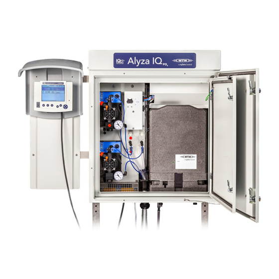
- Page 10 Overview Alyza IQ PO4 Instrument design Abb. 1-2, 10 shows the mains components of the Alyza IQ. figure 1-2 Main components of the Alyza IQ (example: variant with 2 filtration pumps) Cover for the control unit ACM Mounting plate Switch for internal 24 VDC supply Power supply box, behind the mounting plate (120 V / 240 V AC) Channel 2: Filtration pump (installed or free)
- Page 11 Alyza IQ PO4 Overview The measuring unit ready for operation (11) includes the following components – Front cover with light duct for the status LED of the measuring unit – Control unit (ACS) – Locking device of the MultiPort valve (MPV) –...
- Page 12 Overview Alyza IQ PO4 Abb. 1-3, 12 shows the power supply and communication interfaces of the Power supply and Alyza IQ. communication Alyza IQ Control unit ACM Switch box IQ Sensor Net interface 24 V DC e.g. SN 18110258 On/Off Power supply box Daten+Energie...
- Page 13 Alyza IQ PO4 Overview Liquid circle Abb. 1-4, 13 shows the liquid circle of the Alyza IQ. Alyza IQ figure 1-4 Liquid circle Intake lines for channel 1 (1a) and 2 (1b) Filtration pumps for channel 1 (2a) and 2 (2b) Overflow vessels for channel 1 (3a) and 2 (3b) Collection funnel for the sample overflow from the overflow vessels Return line for the sample overflow from the overflow vessels...
-
Page 14: Measuring Unit
Overview Alyza IQ PO4 1.3.2 Measuring unit Abb. 1-5, 14 shows the open measuring unit (without front cover). figure 1-5 Open measuring unit (without front cover) Tube fastening Control unit ACS Locking device of the MultiPort valve (MPV) Receptacle for the MultiPort Valve (MPV) with tubes Contact that detects whether the measuring unit is closed with the front cover. -
Page 15: Chembags
Alyza IQ PO4 Overview agents, standard solutions, cleaning solution). The MultiPort Valve (4) runs each of the moving liquids to the place where they are required. The dosing of the reagents to the sample takes place in the mixing chamber in the MultiPort valve. The sample mixed with reagents is then moved to the cell in the photometer unit (9) to be measured. -
Page 16: Status Leds
Overview Alyza IQ PO4 Other procedures that consume liquids are not counted (e.g. System befüllen). The current counter reading for the ChemBags can be viewed in the Alyza menu (tab Laufzeiten). In the overview, the remaining time is displayed in days (Tage). You can display more details for each ChemBag with <OK>. -
Page 17: Instrument Variants
Alyza IQ PO4 Overview Status LED at the Meaning front cover of the measuring unit No power supply Error The Alyza IQ is stopped, details see log book Red, flashes Close the front cover of the measuring unit immediately. quickly Risk of damage due to the formation of condensation water on electronic components within the measuring unit. - Page 18 Overview Alyza IQ PO4 Type designation Identifier Val- Variant (details) Photometric measurement (yellow method) (Variant: measuring pro- cedure) Measuring range for low concentrations (Variant: Measuring range for higher concentrations measuring range) Sample channels (number) (Variant (Z = 0, 1, 2, depending on the variant of the sample chan- Alyza IQ) nels)
-
Page 19: Sample Filtration
Alyza IQ PO4 Overview The filtration pump is optimally adjusted to the sample filtration available as an Filtration pumps accessory. (instrument vari- Abb. 1-8, 19 shows a filtration pump in the Alyza IQ. ants: 1 channel or 2 channels) figure 1-8 Filtration pump channel 1 Filtration pump (control panel with rotary knob) Sample feed tube (to the overflow vessel) -
Page 20: Name Plates
Overview Alyza IQ PO4 The intake line is in a robust sleeve tube. Intake lines are available in different lengths and with auxiliary heating to protect against frost (depending on the line voltage). Abb. 1-9, 20 shows an application example in a sedimentation tank. figure 1-9 Sample filtration device (installed) Chain (scope of delivery: Basin holder for filtration M 1.5) Guide rail (scope of delivery: Attachment for filtration M 1.5) - Page 21 Alyza IQ PO4 Overview Component Place of the name plate MultiPort valve (MPV) on the side of the MPV Mounting plate on the right-hand side of the switch box Sleeve tubes of the at the end of the line (toward the Alyza IQ ) intake lines and return lines Keep the series numbers on the name plates ready for any service...
-
Page 22: Safety Instructions
Safety instructions Alyza IQ PO4 Safety instructions Safety information 2.1.1 Safety information in the operating manual This operating manual provides important information on the safe operation of the product. Read this operating manual thoroughly and make yourself familiar with the product before putting it into operation or working with it. The operating manual must be kept in the vicinity of the product so you can always find the in- formation you need. -
Page 23: Safe Operation
Alyza IQ PO4 Safety instructions tions. We recommend that you store all datasheets in one folder. Safe operation 2.2.1 Authorized use The authorized use of the Alyza IQ is its use as a sensor in the IQ S ENSOR Only the operation and running of the Alyza IQ according to the instructions and technical specifications given in this operating manual is authorized (see chapter 7 Technical data, ... -
Page 24: Personal Protective Equipment (Ppe)
Safety instructions Alyza IQ PO4 Personal protective equipment (PPE) The PPE includes clothing and other equipment that is used to protect you against risks at your place of work. You must always wear your PPE while doing dangerous jobs to avoid injuries or damage to your health. The following table shows the PPE that is required while dealing with dangerous chemicals such as when exchanging the ChemBags. -
Page 25: Commissioning
Alyza IQ PO4 Commissioning Commissioning IQ S system requirements ENSOR Software versions The operation of the Alyza IQ requires the following software versions in the of the controller IQ S ENSOR and terminal components MIQ/MC2 Version 3.79 or higher MIQ/TC 2020 XT Version 3.79 or higher MIQ/MC3 Version 3.79 or higher... -
Page 26: Accessories Required In Addition
Commissioning Alyza IQ PO4 3.2.2 Accessories required in addition Depending on the application, the following additional accessories are required or recommended for operation. We explicitly recommend that you use original accessories: Mounting The mounting accessories are used to securely install the instrument at the accessories mounting location. -
Page 27: Basic Principles Of Installation
Alyza IQ PO4 Commissioning Basic principles of installation 3.3.1 Requirements of the measurement location The measurement location must meet the environmental conditions specified in section 7.3 General data, 160. Controlled Work on the open instrument (e.g. during mounting, installation, maintenance) ambient may only be carried out under controlled environmental conditions: conditions... -
Page 28: General Installation Instructions
Commissioning Alyza IQ PO4 (according to the technical data of the instrument input or output) – Overvoltage class II surge limiters Suitable disconnecting device (e.g. switch or circuit breaker) for the line power supply of permanently mounted equipment with separate line power connection, –... - Page 29 Alyza IQ PO4 Commissioning Mount the Alyza IQ at a suitable height so that the liquids in the return lines (into the basin) can freely drain off at a steady slope. The Alyza IQ may only be fastened on a wall or fixture with the aid of the two C-rails (housing upright).
-
Page 30: Installing The Housing
Commissioning Alyza IQ PO4 3.3.4 Installing the housing The housing of the Alyza IQ can be installed in the following ways: On the SM stand mount (see section 3.3.5 Installation on the SM stand mount, 30). On a rail (see section 3.3.6 Installation on a rail, 35). ... - Page 31 Alyza IQ PO4 Commissioning Mount the four height adjustable stand feet (3) on the square ground pipes (2) using the enclosed M10 hexagon countersunk head screws. Make sure to use the correct number of plain washers and nuts in the correct order according to Abb.
- Page 32 Commissioning Alyza IQ PO4 Press the plastic protective plugs (1) into the upper ends of both square supporting pipes (3). Using the triangular stabilizing sheets (4), connect both square support- ing pipes (3) with the preassembled ground pipes (2). For each side, use six hexagon head screws with large plain washers, spring washers and locknuts as shown in Abb.
- Page 33 Alyza IQ PO4 Commissioning Make sure that both triangular stabilizing sheets (5) are on the in- side. figure 3-4 Mounting the retaining hooks Retaining hook Mount the four retaining hooks (1) on the supporting pipes. For each hook, use two hexagon head screws, large plain washers, spring wash- ers and locknuts.
- Page 34 Commissioning Alyza IQ PO4 Adjust the four height adjustable stand feet so that the stand mount stands straight. NOTE Always screw the four stand feet to the ground. If the instrument is mounted in the open, please make sure that the installation withstands even severe storm. Mounting the housing figure 3-5 Mounting the housing...
-
Page 35: Installation On A Rail
Alyza IQ PO4 Commissioning figure 3-6 Fixing the housing Angle bracket Fix the housing on both sides with four brackets (1) so it cannot shift sideways. For each bracket, use two hexagon head screws, small plain washers, spring washers and locknuts. 3.3.6 Installation on a rail For installation on a rail, the RM rail mount bracket is required. - Page 36 Commissioning Alyza IQ PO4 Assembling the Proceed as follows to install the housing on the rail: bracket figure 3-7 Connecting the supporting pipes with the cross pipes Protective plug Square supporting pipe Square cross pipe Angle bracket Press the plastic protective plugs (1) into the upper ends of both square supporting pipes (2).
- Page 37 Alyza IQ PO4 Commissioning figure 3-8 Mounting the retaining hooks Retaining hook Mount the four retaining hooks (1) on the supporting pipes. For each hook, use two short hexagon head screws, spring washers and lock- nuts. There are three pairs of holes each for the upper and lower retaining hooks.
- Page 38 Commissioning Alyza IQ PO4 Bracket up- right! Rail If necessary, insert fur- ther clamping strips and washers figure 3-9 Mounting the rail mount bracket on the rail Groove bar Clamping strip Long hexagon head screw Spring washer ba76201d03 05/2020...
- Page 39 Alyza IQ PO4 Commissioning Attach the rail mount bracket to two suitable horizontal rail pipes with the aid of the four clamping devices. Each clamping device consists of a groove bar (1), a terminal strip (2), two long hexagon head screws (3), two nuts (4) and two spring washers (5).
-
Page 40: Installation On A Wall
Commissioning Alyza IQ PO4 figure 3-11Fixing the housing (on the right: Detailed view) Angle bracket Fix the housing on both sides with four brackets (1) so it cannot shift sideways. For each bracket, use two short hexagon head screws, small plain washers, spring washers and locknuts. - Page 41 Alyza IQ PO4 Commissioning figure 3-12Drilling dimensions for mounting the WM wall mounting assembly Screw tight the four retaining hooks of the wall mounting set. Mount the housing by hooking the C-rails fixed on its rear side into the four retaining hooks. NOTE To prevent the instrument from shifting laterally, the fixing screws of the C-rails ...
-
Page 42: Removing The Transport Protection Of The Measuring Unit
Commissioning Alyza IQ PO4 figure 3-13Housing of the Alyza IQ in the WM wall mounting assembly Retaining hook Fixing screws of the C-rail 3.3.8 Removing the transport protection of the measuring unit The transport protection in the housing of the Alyza IQ fixes the measuring unit in its position with the aid of 3 spacers made of foam. -
Page 43: Connecting The Cables To The Control Unit Acm
Alyza IQ PO4 Commissioning figure 3-14Transportation safety devices Control unit with connectors Transport protector 1 in the front Transport protector 2 in the front Transport protector 3 in the background Measuring unit Pull the two transport protectors (2, 3) out to the front. Carefully move the transport protector (4) of the measuring unit (5) upward and then pull it out to the front. -
Page 44: Mounting The Cover Plate For The Control Unit Acm
Commissioning Alyza IQ PO4 figure 3-15Cable of the control unit ACM 3-pole connection (mains) 4-pole connection (data) USB connection RJ45 connection 3.3.10 Mounting the cover plate for the control unit ACM The cover plate for the control unit ACM covers the control unit ACM and the ca- bles connected to it. -
Page 45: Installing The Bug Screen And Condensate Drain Adapter
Alyza IQ PO4 Commissioning figure 3-16Cover plate for the control unit ACM Knurled-head screws to mount the cover plate Cover plate for the control unit ACM Cables for power supply Measuring unit 3.3.11 Installing the bug screen and condensate drain adapter Bug screen The bug screen protects the interior of the Alyza IQ against insects coming in through the air intake opening in the bottom of the housing. - Page 46 Commissioning Alyza IQ PO4 figure 3-17Mounting the bug screen and condensate drain adapter Condensate drain tube (black) at the housing bottom Bug screen Frame with seal Condensate drain adapter with 2 screws Condensate drain tube (transparent) 4 knurled-head screws Screw the condensate drain adapter (4) with 2 screws to the frame (3) Installation so that the tube nozzle of the adapter is on the outside of the frame.
-
Page 47: Mounting The Terminal Holder (Tm)
Alyza IQ PO4 Commissioning figure 3-18Mounted bug screen and condensate drain adapter Frame Bug screen Condensate drain adapter One of the 4 knurled-head screws 3.3.12 Mounting the terminal holder (TM) Operating the Alyza IQ, especially while maintenance activities are being exe- cuted at the open measuring unit, requires a terminal mounted in the vicinity (e.g. - Page 48 Commissioning Alyza IQ PO4 figure 3-19Installed terminal holder TM (view of the rear side) Example: Installation on an SM stand mount Upper bracket Upper angle bracket Bore holes for the canopy Mounting sheet Lower bracket Lower angle bracket Preparing the The terminal holder is installed at the left-hand side of the Alyza IQ.
- Page 49 Alyza IQ PO4 Commissioning Position the second bracket (5) on the mounting stand and insert the ends of the bracket in the bore holes of the angle bracket. Fix the angle bracket (6) to the bracket loosely with 2 nuts. Installation on a Screw the mounting sheet (4) to both brackets (2, 6) with 4 hexagon mounting stand or...
-
Page 50: Connecting The Power Cable And Heat Tracing Lines
Commissioning Alyza IQ PO4 figure 3-20Mounted terminal holder TM with canopy, MIQ/JB and MIQ/TC 2020 3G 3.3.13 Connecting the power cable and heat tracing lines For all work done with the housing open: If the Alyza IQ was already in operation: Before opening the measuring unit, start the maintenance routine at the terminal. - Page 51 Alyza IQ PO4 Commissioning figure 3-21Cable glands for intake lines and return lines (view from inside and from below) Cable gland (front) for return line 2 (in the example, sealed with yellow plug) Cable gland (2nd from the front) for return line 1 (in the example: waste from the measuring unit and sample overflow from the overflow vessels) Cable gland (3rd from the front) for intake line 1 (channel 1)
- Page 52 Commissioning Alyza IQ PO4 Opening the power WARNING If the power supply is connected incorrectly, there may be (to connect the danger to life from electric shock. heat tracing) Pay attention to the following points during installation: The power supply box may only be connected to the power supply by a qualified electrician.
- Page 53 Alyza IQ PO4 Commissioning Switching off the Switch off all filtration pumps (STOP). power supply Switch off the 24 V power supply. Switch the power line potential free. Removing the Unscrew the 2 fixing screws of the cover (on the top right side in the mounting plate housing) and remove the cover of the ACM.
- Page 54 Commissioning Alyza IQ PO4 Before opening: ES: Antes de abrir: figure 3-22Mounting plate Mounting plate Fixing screws at the upper edge Fixing nuts at the lower edge Switch box with 24 VDC switch Remove the mounting plate: Lift the mounting plate upward over the threaded pins. ...
- Page 55 Alyza IQ PO4 Commissioning figure 3-23Connections of the power supply box Power supply module Ventilator Power supply filter Connecting terminals for the heat tracing lines 4 - 7: yellow/green (protective earth conductor) 8 - 11: gray 12 - 15: blue Power supply of the heat tracing lines Overvoltage protection Power line...
- Page 56 Commissioning Alyza IQ PO4 On the underside of the power supply box, remove the protective plugs from those cable glands you need to connect the cables. Unused cable glands have to be closed with the supplied black plugs. Connecting the Only for variants with 2 sample channels: intake lines and Run the intake line for channel 2 through the big rear cable gland (from...
- Page 57 Alyza IQ PO4 Commissioning To guide the sample return into the basin and dispose of the chemicals waste separately: Run the return line for sample through the front big cable gland at the housing bottom. – The sleeve tube should end flush with the tube inside the housing so that a collection funnel can be installed.
- Page 58 Commissioning Alyza IQ PO4 Slide the nut of the cable gland (of the power supply box) over the cable of the heat tracing. First run the wire with the greatest diameter (protective earth conductor, yellow/green) through the sealing of the cable gland. Then run the two thinner wires (black) of the heat tracing through the sealing of the cable gland.
-
Page 59: Mounting The Collection Funnel
Alyza IQ PO4 Commissioning Reinserting the Insert the mounting plate: mounting plate Plug the mounting plate on the threaded pins inside the housing. Tighten the 2 fixing screws (2) at the upper edge of the mounting plate. Tighten the 2 fixing nuts (3) at the bottom of the mounting plate. Re-establish the cable connections and the connection of the tubes and liquid lines. - Page 60 Commissioning Alyza IQ PO4 It is possible to dispose of the sample overflow and chemical waste from the measuring unit separately by using a second collection fun- nel (accessory WF Set). The second collection funnel is installed at the front cable gland. There the sample return is transported out of the housing separately (see section 3.3.15 Mounting the WF Set (collection funnel for sample overflow), ...
- Page 61 Alyza IQ PO4 Commissioning Mounting figure 3-25Collection funnel for the common discharging of all liquids Heating line of the heat tracing (attached to the fixing bracket with a cable tie) Waste tube of the measuring unit Sample overflow tube from the overflow vessel Rubber cover of the collection funnel (close any unused openings with plugs) Cable ties...
-
Page 62: Mounting The Wf Set (Collection Funnel For Sample Overflow)
Commissioning Alyza IQ PO4 Put the waste tube (2) of the measuring unit into the collection funnel through the small opening of the rubber cover (4). The liquid in the waste tube must be able to flow freely (steady slope, no kinking, no damage). - Page 63 Alyza IQ PO4 Commissioning Insert the collection funnel (7) in the opening of the cable gland (9) in the housing: the beveled side of the collection funnel (7) points to the heat tracing the drain of the collection funnel flows into the return line for the sam- ple return.
-
Page 64: Installing The Fm/Pc Filter Module And M 1.5 Basin Holder For Filtration
Commissioning Alyza IQ PO4 figure 3-26 Collection funnel for the separate discharge of all liquids Heating line of the heat tracing (attached to the fixing bracket with a cable tie) Waste tube of the measuring unit Sample overflow tube from the overflow vessel Plug for the rubber cover Rubber cover of the collection funnel (seal unused openings of the rubber cover with plugs) - Page 65 Alyza IQ PO4 Commissioning In special cases (e.g. in a channel) it is better to mount the FM/PC filter module in a horizontal position in the flow direction. An adapter for horizontal mounting is available as an accessory. The filter module (FM/PC) and the slide must be completely submersed (max.
-
Page 66: Connecting The Tubes And Liquid Lines
Commissioning Alyza IQ PO4 Insert the slide of the filter module in the rail and lower it into the basin with the aid of the chain. Fix the end of the chain outside the basin. Run the intake line to the Alyza IQ. Fix the sleeve tube with cable ties at some suitable places as necessary. - Page 67 Alyza IQ PO4 Commissioning Before opening: ES: Antes de abrir: figure 3-28Completely connected lines Channel 1: Filtration pump Channel 1: Sample feed tube (filtration pump - overflow vessel) Channel 1: Intake line Channel 1: Overflow vessel Channel 1: Sample overflow tube (overflow vessel - collection funnel) Channel 1: Sample tube (overflow vessel - measuring unit) Channel 2: Overflow vessel Channel 2: Intake line...
- Page 68 Commissioning Alyza IQ PO4 Connect the intake line 2 to the filtration pump 2. Connect the sample tubes to the overflow vessels. The sample tube (channel 2) for overflow vessel 2 has a red labeling. Before opening: ES: Antes de abrir: figure 3-29Opening for the sample tubes Grooves for the sample tubes through the insulation of the measuring unit...
-
Page 69: Setting Up A Connection With The Iq Sensor Net System
Alyza IQ PO4 Commissioning Insert the sample overflow tubes from the overflow vessels into the col- lection funnel for the sample overflow. Collection funnel at the foremost cable gland: (with separate disposal of the chemical waste from the measuring unit) ... -
Page 70: Taking The Filtration Pumps Into Operation
Commissioning Alyza IQ PO4 3.3.19 Taking the filtration pumps into operation Make sure that all lines (intake lines, return lines) and tubes (sample feed tube, sample overflow tube, sample tube, waste tube) in the Alyza IQ are connected correctly. Set the 24 VDC switch on the mounting plate to ON (I pressed upward). Use the rotary knob to set the pump capacity to 80 ... - Page 71 Alyza IQ PO4 Commissioning Open and then close again the ventilation valve (1). Fill the intake line with water manually: – Switch off the filtration pump. – Pull the intake line off the filtration pump. – Fill the intake line with water (e.g. using a wash bottle). –...
-
Page 72: Initial Commissioning
Commissioning Alyza IQ PO4 Initial commissioning For all work done with the housing open: If the Alyza IQ was already in operation: Before opening the measuring unit, start the maintenance routine at the terminal. Note the environmental conditions (see Abb. 3.3.1, 27). ... -
Page 73: Stick The Label (National Language) Onto The Locking Device Of The Multiport Valve
Alyza IQ PO4 Commissioning Is sample present in the overflow vessels? Does the sample in the overflow vessels meet the quality requirements (see section 7.2 Application conditions, 159)? Is the Alyza IQ connected to the IQ S ENSOR (MIQ/JB + Terminal/Controller, is the Alyza IQ displayed as a sensor on the IQ S... - Page 74 Commissioning Alyza IQ PO4 install the replacement parts required. For the commissioning you have to know how to: Open the measuring unit, Install the MultiPort valve (MPV), Install the ChemBag, Install the tube at the MultiPort valve (MPV) (if the functions Untergr.-korr.
- Page 75 Alyza IQ PO4 Commissioning Put on your personal protective equipment (PPE) and chemical resis- tant gloves (see section 2.4 Personal protective equipment (PPE), 24). WARNING Dangerous chemicals. Improper use of chemicals can cause damage to your health. Heed the following rules: ...
-
Page 76: Preparing The Alyza Iq For Measuring
Commissioning Alyza IQ PO4 Re-insert the front cover of the measuring unit. Close the housing of the Alyza IQ. Prepare the Alyza IQ for measuring (see section 3.4.4 Preparing the Alyza IQ for measuring, 76) 3.4.4 Preparing the Alyza IQ for measuring After completing the install wizard, carry out some further steps at the terminal of the IQ S ENSOR... - Page 77 Alyza IQ PO4 Commissioning figure 3-35Tab Wartung Carry out the function Alyza IQ STARTEN. Measurement is started and the measured value is displayed in the measured value display after approx. 5 ... 7 minutes. Wait for the temperature adjustment to be completed. If necessary, switch off the maintenance condition.
-
Page 78: Measurement / Operation
Measurement / Operation Alyza IQ PO4 Measurement / Operation General operating principles Contrary to the general operating principles of the IQ S , the Alyza IQ ENSOR is operated via a separate menu (Alyza menu) at the IQ S terminal. ENSOR Opening the Alyza In the measured value display, use <... -
Page 79: Measurement Operation
Alyza IQ PO4 Measurement / Operation – Activate or terminate the maintenance condition – Start calibration – Start the service functions Measurement operation 4.2.1 Determination of measured values The Alyza IQ determines the measured values with a chemical analyzing proce- dure. - Page 80 Measurement / Operation Alyza IQ PO4 nal. figure 4-2 Measured value display of the Alyza IQ The current Alyza IQ measured values are also displayed in the Alyza menu, tab Status. More detailed information on the current status is available here, (e.g. next measurement, next cleaning, next calibration).
-
Page 81: Settings For The Alyza Iq
Alyza IQ PO4 Measurement / Operation Measured value Function display CLEAN Autom.Reinigung is being carried out. Autom.Kalibrierung is being carried out. Settings for the Alyza IQ For the Alyza IQ, the settings are done like that for the other IQ S sen- ENSOR sors in the menu Einstellungen Sensoren/Differenzsensoren (IQ S... - Page 82 Measurement / Operation Alyza IQ PO4 Setting menu (PO4) Possible values Description Messbereich With the setting Depending on the Messmodus setting, 0,02 .. 15,00 mg/L Messmodus: PO4-P different measuring ranges can be 0,2 .. 50,0 mg/L selected. 0,02 .. 15,00 ppm For each measured parameter, a low 0,2 ..
- Page 83 Alyza IQ PO4 Measurement / Operation Setting menu (general set- Possible values Description tings) With the setting The instrument displays the median of Medianfilter the last 3 measurements as the mea- surement value. Autom.Reinigung Switches the automatic cleaning func- tion on or off ...
- Page 84 Measurement / Operation Alyza IQ PO4 Setting menu (general set- Possible values Description tings) Ref.Zeit Stunden 0… …23 Defines the start time from which the automatic calibration procedures will Ref.Zeit Minuten …59 take place at the set interval (default setting: 8:00 o'clock) PLEASE NOTE: Recommended start time for...
-
Page 85: Priority
Alyza IQ PO4 Measurement / Operation The Autom.Reinigung, Autom.Kalibrierung and Messintervall set- tings may result in the overlapping of the carrying out of different functions. In this case, the functions are carried out according to priority. 4.3.2 Priority Function Priority Duration (min) Autom.Reinigung 6 (1-channel variant) -
Page 86: Calibration
Measurement / Operation Alyza IQ PO4 Calibration record / The result of a calibration is stored in the calibration history (see Alyza menu / calibration history tab Historie / Kalibrierhistorie). Maintenance To carry out a calibration procedure (automatically or manually), the mainte- condition nance condition is always automatically activated for the Alyza IQ in the IQ S... - Page 87 Alyza IQ PO4 Measurement / Operation figure 4-4 Measured value display of the Alyza IQ Using <C>, open the Alyza menu for the Alyza IQ. Using < >, switch to the Wartung tab. figure 4-5 Tab Wartung Open the menu item Alyza IQ STOPPEN. Carry out a function to stop the running operation.
- Page 88 Measurement / Operation Alyza IQ PO4 Carry out Carry out the function / Kalibrieren (1-Punkt) or Kalibrieren (2-Punkt). calibration For 1-point calibration the ChemBag at the connector S1 is always used. The calibration procedure runs automatically. The calibration result is displayed after the calibration standards have been measured.
-
Page 89: Calibration History
Alyza IQ PO4 Measurement / Operation 4.4.3 Calibration history The calibration history of the Alyza IQ is available in the Alyza menu (tab Historie / Kalibrierhistorie). Example and explanation of a calibration history (see section 4.5.3 Information on maintenance activities and calibration procedures (tab Historie), 93) 4.4.4 Reactivating the last valid calibration Manual calibration If a manual calibration procedure is unsuccessful, the measuring operation can... -
Page 90: Information On The Alyza Iq
Measurement / Operation Alyza IQ PO4 Information on the Alyza IQ In the Alyza menu, there is comprehensive information available on the current status of the Alyza IQ: Current operating condition (measuring, calibration, etc.) Schedule for the next interval-controlled actions, e.g. measuring, calibrating, cleaning (tab Status) ... -
Page 91: Information On The Expected Lifetimes Of Replacement Parts
Alyza IQ PO4 Measurement / Operation comprises the current measured values and also the schedule for the next inter- val-controlled actions, e.g. measuring, calibrating or cleaning. figure 4-6 Operating condition (tab Status, example 2-channel variant) In the Status tab, the following information on the current operating condition is available: ... - Page 92 Measurement / Operation Alyza IQ PO4 figure 4-7 Overview Laufzeiten (tab Laufzeiten) The estimated times remaining until the next exchange are shown in days in the overview. If the times remaining are short, this is also indicated in the display. Remaining time Signal <...
-
Page 93: Information On Maintenance Activities And Calibration Procedures
Alyza IQ PO4 Measurement / Operation More details on the lifetime of a replacement part can be opened with <OK> . figure 4-8 Information on Laufzeiten, detailed view (Tab Laufzeiten) 4.5.3 Information on maintenance activities and calibration procedures (tab Historie) The Alyza IQ histories provide an overview of the replacement parts installed, the maintenance activities carried out, and the calibration procedures per- formed. - Page 94 Measurement / Operation Alyza IQ PO4 Installierte Wartungsteile figure 4-9 Installierte Wartungsteile (tab Historie / Installierte Wartungsteile) The list Installierte Wartungsteile shows a list of all components that have to be replaced regularly, i.e.when the use-by period has expired. The installation date and expiry date of a component are recorded when the component is installed.
- Page 95 Alyza IQ PO4 Measurement / Operation The Kalibrierhistorie list shows the last calibration results (see section 4.4.3 Cal- Kalibrierhistorie ibration history, 89). Current calibration data Chronological list of the last calibration procedures figure 4-10Kalibrierhistorie Alyza IQ The calibration history provides the following information: Date time ...
-
Page 96: More Information On The Alyza Iq (Tab Info)
Measurement / Operation Alyza IQ PO4 4.5.4 More information on the Alyza IQ (Tab Info) In the Info tab there is more information on the Alyza IQ, which may be helpful in the case of errors or implausible measured values. The following information is displayed: ... -
Page 97: Transferring To A Usb Memory Device A Selection Of Important
Alyza IQ PO4 Measurement / Operation 4.6.1 Transferring to a USB memory device a selection of important oper- ating data These operating data provide an overview of important settings and data for the functioning of your Alyza IQ. Measurement settings ... -
Page 98: Software Update For The Alyza Iq
Measurement / Operation Alyza IQ PO4 Select the function, Service-Dateien auf USB-Speicher übertragen. Follow the instructions on the display. Remove the USB memory device from the interface "USB0". If necessary, re-insert the previously removed USB plug into the unla- beled USB interface. Reinsert the cover and fix it with the 2 fixing screws. - Page 99 Alyza IQ PO4 Measurement / Operation Plug the USB memory device with the software update IQ S ENSOR "Update Pack (L1)" to the USB interface "USB0". On the terminal, switch to the measured value display of the IQ S ENSOR Note Interrupting the power supply during the update process may damage the Alyza IQ.
-
Page 100: Maintenance And Cleaning
Maintenance and cleaning Alyza IQ PO4 Maintenance and cleaning Hazard warnings Read the chapter 2 Safety instructions, 22 before doing any maintenance work. This is important for your personal safety. NOTE The interior of the measuring unit is temperature-controlled to 20 °C (68 °F). With ambient temperatures over 25 °C (77 °F), condensation water may develop on the cool surfaces and cause damage when the measuring unit is opened. -
Page 101: Opening The Locking Device Of The Multiport Valve ("Before Opening: Drain The System")
Alyza IQ PO4 Maintenance and cleaning Opening the locking device of the MultiPort valve ("Before opening: Drain the system") The MultiPort Valve is the core element for the distribution and dosing of the liq- uids in the measuring unit. The MultiPort valve is connected to the liquids by ex- actly positioning the MultiPort valve and pressing it to the seals. - Page 102 Maintenance and cleaning Alyza IQ PO4 Drain all tubes (Wartung /Manuelle Funktionen / System entleeren). If emptying via the Alyza menu is not possible, carry out the manual emptying (section 5.9 Emptying the system manually, 138). Opening the Put on your personal protective equipment (PPE) and chemical resis- locking device tant gloves (see section 2.4 Personal protective equipment (PPE), ...
- Page 103 Alyza IQ PO4 Maintenance and cleaning Make sure that the connected ChemBags are safely suspended from the supporting rod, and that they are not pressed or moved while the locking device is open. Make sure that the sample tubes (from the overflow vessel to the mea- suring unit) are fixed in the recesses at the left-hand side of the measur- ing unit.
-
Page 104: Replacement Parts, Accessories
Maintenance and cleaning Alyza IQ PO4 NOTE To avoid damage to the measuring unit caused by leaking chemicals, make sure that the following requirements are met while you are work- ing with the locking device open: The connected ChemBags are safely suspended from the supporting rod. - Page 105 Alyza IQ PO4 Maintenance and cleaning Type Replacement parts Order (ChemBag sets) number S-PO4/1-0.0 Calibration standard 0.0 for mea- 827526 suring range 1 (MR1, low MR) S-PO4/1-1.0 Calibration standard 1.0 for mea- 827527 suring range 1 (MR1, low MR) S-PO4/1-10.0 Calibration standard 10.0 for mea- 827528 suring range 1 (MR1, low MR) or...
-
Page 106: Overview Of The Maintenance And Cleaning Activities
Maintenance and cleaning Alyza IQ PO4 Accessories Type Accessories Order (optional) number WF Set Mounting set for a collection funnel 827187Y Mounting set for the terminal 822000Y holder Check valve 827186Y CheckValve (for the sample feed tube) to clean the filter plate chemically) NOTE Detergents containing tensides can cause damage. - Page 107 Alyza IQ PO4 Maintenance and cleaning Regular Regular maintenance Interval maintenance activities Measuring unit Installing/replacing the Approx. 12 months (simple mainte- MultiPort valve (MPV) with a measuring interval of nance activities 10 min. on site) Depending on the fre- quency of the measuring, cleaning or calibrating pro- cedures, the maintenance intervals will be shorter or...
-
Page 108: Installing / Exchanging The Chembags, Mpv, Tubes
Maintenance and cleaning Alyza IQ PO4 Regular maintenance Interval Housing Cleaning the filter mats at Depending on contamina- the housing tion (see section 5.7.2, 130) Cleaning the housing As required (see section 5.7.1, 130) Bug screen As necessary Maintenance Maintenance activities at the power supply box are only required for work at the activities at the... - Page 109 Alyza IQ PO4 Maintenance and cleaning Maintenance During the initial commissioning, the install wizard guides you preparation through the maintenance preparation. Continue with section Installing the MultiPort valve (MPV) and tubes , 111. Proceed as follows to carry out maintenance activities of the liquid circle of the Alyza IQ: Starting the In the measured value display, use <...
- Page 110 Maintenance and cleaning Alyza IQ PO4 figure 5-4 Tab Wartung Carry out the Wartungszustand einschalten function. On the IQ S , the maintenance condition for the Alyza IQ is ENSOR switched on. Carry out the Alyza IQ STOPPEN function to stop the running operation. Carrying out WARNING maintenance...
- Page 111 Alyza IQ PO4 Maintenance and cleaning Put on your personal protective equipment (PPE) and chemical resis- tant gloves (see section 2.4 Personal protective equipment (PPE), 24). Open the Wartung Messeinheit menu. Select the function, Öffnen der Messeinheit vorbereiten. Follow the instructions on the display. The procedure starts the temperature adjustment of the measuring unit and the selection of the parts that have to be installed or replaced.
- Page 112 Maintenance and cleaning Alyza IQ PO4 figure 5-5 Tubes in the tube fasteners WARNING Dangerous chemicals. Do not open the locking device of the MultiPort valve if the maintenance activities at the measuring unit have not been completed. Leaking chemicals can cause health problems and damage the measuring unit.
- Page 113 Alyza IQ PO4 Maintenance and cleaning Make sure that the connected ChemBags are safely suspended from the supporting rod, and that they are not pressed or moved while the locking device is open. Make sure that the sample tubes (from the overflow vessel to the mea- suring unit) are fixed in the recesses at the left-hand side of the measur- ing unit.
- Page 114 Maintenance and cleaning Alyza IQ PO4 NOTE To avoid damage to the measuring unit caused by leaking chemicals, make sure that the following requirements are met while you are work- ing with the locking device open: The connected ChemBags are safely suspended from the supporting rod.
- Page 115 Alyza IQ PO4 Maintenance and cleaning Color coding Connection of Green (reagent) MPV - ChemBag R Orange (calibration stan- MPV - ChemBag S dard) Blue (cleaning solution) MPV - ChemBag C Screw the new tubes onto the pressure plate of the MultiPort valve. Use the special tool for this.
- Page 116 Maintenance and cleaning Alyza IQ PO4 figure 5-7 ChemBags removed to be exchanged Unscrew the coupling of the tube from the ChemBag connector. Unscrew the protection cap of the ChemBag to be connected. The ChemBag connector points upward. Screw the protective cap onto the connector of the empty ChemBag. The ChemBags with the longest lifetime do not have to be ex- changed often.
- Page 117 Alyza IQ PO4 Maintenance and cleaning figure 5-8 Recommended order of the ChemBags on the supporting rod Screw the coupling of the tube tightly onto the connector of the new ChemBag. Make sure that the codings of the ChemBag and tube agree (symbol, color, number).
- Page 118 Maintenance and cleaning Alyza IQ PO4 figure 5-9 Connecting the ChemBag Color coding of the tube Color coding of the ChemBag Carefully turn the ChemBag upside down. The connector points downward. If necessary, slightly knock on the connector of the ChemBag to remove any small bubbles from the connector.
-
Page 119: Cleaning The Sample Filtration And Sample Feed
Alyza IQ PO4 Maintenance and cleaning Terminating the After maintenance activities at the measuring unit: maintenance Close the front cover of the measuring unit and the doors of the routine Alyza IQ. Carry out the Messung vorbereiten function. The temperature control of the Alyza IQ is started. Wait for the temperature of the Alyza IQ to be regulated (display in the tab Status). - Page 120 Maintenance and cleaning Alyza IQ PO4 NOTE Dirt particles and contamination in the sample line can block the valves of the measuring unit. During the cleaning activities, make sure that no dirt particles get into the open tube ends or the connector of the filter module. Protect the open tubes and connectors during the cleaning activities, e.g.
-
Page 121: Chemical Cleaning Of The Filter Plate
Alyza IQ PO4 Maintenance and cleaning Switch on the filtration pump with the Start key. Restarting the Restart the Alyza IQ and switch off the maintenance condition at the measuring IQ S ENSOR operation 5.6.2 Chemical cleaning of the filter plate Chemical cleaning is recommended if mechanical cleaning no longer achieves any significant improvement, i.e. - Page 122 Maintenance and cleaning Alyza IQ PO4 Pre-cleaning Prior to each chemical cleaning, pre-clean the membrane with the spe- cial brush and rinse it with water (see section 5.6.1 Mechanical cleaning of the filter plate, 119). Dismount the filter unit from the slide. Dismount the intake line from the filter unit.
-
Page 123: Storing A Used And Cleaned Filter Plate
Alyza IQ PO4 Maintenance and cleaning 5.6.3 Storing a used and cleaned filter plate Proceed as follows to store the filter plate: Clean the filter plate mechanically. Clean the filter plate chemically. Rinse the filter plate under flowing tap water. To protect it against drying out, store the filter plate in the Filter-CL cleaning container or in a sealed plastic bag. -
Page 124: Cleaning The Sample Feed And Overflow Vessel
Maintenance and cleaning Alyza IQ PO4 Remounting the Insert a new filter plate in the lower frame part. filter plate Place the upper frame part onto the lower frame part with the built-in fil- ter plate. Insert the V4A countersunk screws and tighten them by hand. The fixing ring and lower part of the housing must be pressed together and flush (without gap). - Page 125 Alyza IQ PO4 Maintenance and cleaning Abb. 5-11, 125 shows the intake line on a mounted filter module in a sedimen- tation tank. figure 5-11Sample filtration device (installed) Chain (scope of delivery: basin holder for filtration M 1.5) Guide rail (scope of delivery: basin holder for filtration M 1.5) Height adjustable slide (scope of delivery: Suction line) Intake line (scope of delivery: Suction line) Sleeve tube (scope of delivery: Suction line)
- Page 126 Maintenance and cleaning Alyza IQ PO4 figure 5-12Measured value display of the Alyza IQ Using the <C> key, switch to the Alyza menu. Using < >, switch to the Wartung tab. figure 5-13Tab Wartung Carry out the Wartungszustand einschalten function. On the IQ S , the maintenance condition for the Alyza IQ is ENSOR...
- Page 127 Alyza IQ PO4 Maintenance and cleaning Carrying out WARNING maintenance Dangerous chemicals. activities Improper use of chemicals can cause damage to your health. Heed the following rules: Read the labels of the ChemBags and follow the safety instructions Wear protective equipment (protective goggles, chemi- cal resistant gloves) For all activities at the open measuring unit: ...
- Page 128 Maintenance and cleaning Alyza IQ PO4 NOTE Detergents containing alcohol will damage the overflow vessel. If necessary: exchange or clean the filter plate (see section 5.6.1 Mechanical cleaning of the filter plate, 119). Disconnect the intake line from the filter module and put it in a container with cleaning solution (recommendation: see section 5.3 Replacement parts, accessories, ...
- Page 129 Alyza IQ PO4 Maintenance and cleaning Switch on the filtration pump with the Start key. Cleaning solution is drawn in through the intake line until it flows into the bottle at the open line end. Leave the filtration pump switched on until the minimum quantity (see ...
-
Page 130: Maintenance Activities At The Housing
Maintenance and cleaning Alyza IQ PO4 Maintenance activities at the housing 5.7.1 Cleaning the housing of the Alyza IQ Outside Clean the outside of the housing with a brush, water and dish-washing solution. Inside Clean the inside with a moist (not dripping) cloth, water and dish-washing solu- tion. - Page 131 Alyza IQ PO4 Maintenance and cleaning Open the upper filter mat holder with the aid of a screwdriver by levering it off and exchange the upper filter mat (see Abb. 5-15, 131). figure 5-15Exchanging the upper filter mat Upper filter mat holder Upper filter mat Opening for screwdriver Press the upper filter mat holder shut again.
-
Page 132: Checking The Temperature Control
Maintenance and cleaning Alyza IQ PO4 5.7.3 Checking the temperature control For correct measured values, it is required to control the temperature of some areas of the Alyza IQ. The Alyza IQ has 3 areas that are temperature-controlled differently: Range Temperature control Housing inside +5 ... -
Page 133: Maintenance Activities At The Power Supply Box
Alyza IQ PO4 Maintenance and cleaning Maintenance activities at the power supply box WARNING If the power supply is connected incorrectly, there may be danger to life from electric shock. Pay attention to the following points during installation: The power supply box may only be connected to the power supply by a qualified electrician. - Page 134 Maintenance and cleaning Alyza IQ PO4 Switch the power line potential free. Removing the Unscrew the 2 fixing screws of the cover (on the top right side in the mounting plate housing) and remove the cover of the ACM. If the filtration pumps have already been in operation, sample liquid may escape when the tubes are unscrewed.
- Page 135 Alyza IQ PO4 Maintenance and cleaning Before opening: ES: Antes de abrir: figure 5-17Mounting plate Mounting plate Fixing screw at the upper edge Fixing nuts at the lower edge Switch box with 24 VDC switch Remove the mounting plate: Lift the mounting plate upward over the threaded pins. ...
- Page 136 Maintenance and cleaning Alyza IQ PO4 figure 5-18Connections of the power supply box Power supply module Ventilator Power supply filter Connecting terminals for the heat tracing lines 4 - 7: yellow/green (protective earth conductor) 8 - 11: gray 12 - 15: blue Power supply of the heat tracing lines Overvoltage protection Power line...
- Page 137 Alyza IQ PO4 Maintenance and cleaning Details on connecting the heat tracing and power cable: See section 3.3.13 Connecting the power cable and heat tracing lines, 50. Check whether all connections are made correctly. Tighten the cable glands on the power supply box with a torque of 2.5 The cable glands protect the power supply box from dust and moisture.
-
Page 138: Emptying The System Manually
Maintenance and cleaning Alyza IQ PO4 Restarting the Complete the maintenance routine (see section 3.4.4 Preparing the measuring Alyza IQ for measuring, 76). operation Emptying the system manually NOTE With manual emptying, the is the risk of material damage due to spilled chemi- cals. - Page 139 Alyza IQ PO4 Maintenance and cleaning Put on your personal protective equipment (PPE) and chemical resis- tant gloves (see section 2.4 Personal protective equipment (PPE), 24). Remove the front cover of the measuring unit. Using one hand, grip the handle at the upper edge of the front cover of the measuring unit.
- Page 140 Maintenance and cleaning Alyza IQ PO4 figure 5-19ChemBags removed from the supporting rod Switch off all filtration pumps (STOP). Switch off the 24 V power supply at the switch box. If the filtration pumps have already been in operation, sample liquid may escape when the tubes and liquid lines are unscrewed.
- Page 141 Alyza IQ PO4 Maintenance and cleaning Close the locking device of the MultiPort valve to absorb leaked liquids with the absorbent paper. figure 5-20Absorbent paper in the receptacle of the MultiPort valve Open the locking device of the MultiPort valve. Remove the absorbent paper.
-
Page 142: Complex Maintenance- And Cleaning Activities In The Measuring Unit
Alyza IQ PO4 5.10 Complex maintenance- and cleaning activities in the measur- ing unit For complex maintenance activities or cleaning activities in the measuring unit we recommend that you dismount the measuring unit and transport it to a clean laboratory environment. When the measuring unit is dismounted, its parts are more easily accessible and the environmental conditions (temperature, cleanliness) are more suitable for complex maintenance activities or cleaning activities to be carried out. -
Page 143: Carrying Out Complex Maintenance Activities
Alyza IQ PO4 Carefully take the front cover out to the front. Put the front cover down in a clean place. Pull the fixation (2) of the measuring unit to the cooling unit out from below. Take the measuring unit up off the cooling unit and tilt it backwards. Then remove the measuring unit from the housing of the Alyza IQ, to the front. -
Page 144: Decommissioning
Alyza IQ PO4 Mount the measuring unit to the cooling unit (with the fixation of the measuring unit). Re-insert the waste tube into the collection funnel. Screw the sample tubes of the measuring units to the overflow vessels. The sample tube for overflow vessel 2 is labeled red. Re-plug the 4 data cables of the measuring unit to the ACM. -
Page 145: Preparing The Decommissioning
Alyza IQ PO4 5.11.2 Preparing the decommissioning For all activities at the open measuring unit: Note the environmental conditions (see section 3.3.1 Require- ments of the measurement location, 27). With low ambient temperatures, make sure that the liquids do not freeze while the maintenance activities are carried out. -
Page 146: Decommissioning The Measuring Unit
Alyza IQ PO4 figure 5-23Tab Wartung (example Alyza IQ PO4) Carry out the function Wartungszustand einschalten. On the IQ S , the maintenance condition for the Alyza IQ is ENSOR switched on. Carry out the Alyza IQ STOPPEN function to stop the running operation. 5.11.3 Decommissioning the measuring unit Open the Wartung Messeinheit menu. - Page 147 Alyza IQ PO4 figure 5-24Alyza IQ, housing open, variant with 2 channels Switch box 24V switch (at the switch box) 2 plugs at the switch box Sample tubes (2 channels) Connection sample tube to overflow vessel 1 Connection sample feed tube to overflow vessel 1 (quick fastener) Waste tube of the measuring unit Fixation of the measuring unit to the cooling unit...
- Page 148 Alyza IQ PO4 WARNING Dangerous chemicals. Improper use of chemicals can cause damage to your health. Heed the following rules: Read the labels of the ChemBags and follow the safety instructions Wear protective equipment (protective goggles, chemi- cal resistant gloves) If the filtration pumps have already been in operation, sample liquid may escape when the tubes and liquid lines are unscrewed.
-
Page 149: Transport, Storage
Alyza IQ PO4 Now carry out the intended activities, such as: Dismount the measuring unit and carry out maintenance activities (see section 5.10 Complex maintenance- and cleaning activities in the measuring unit, 142) Prepare and carry out storage or transport (see section 5.12 Transport, storage, ... - Page 150 Alyza IQ PO4 figure 5-25Transportation safety devices 1 Control unit with connectors 2 Transport protector 1 in the front 3 Transport protector 2 in the front 4 Transport protector 3 in the background 5 Measuring unit Preparing the Close the doors of the Alyza IQ and secure the doors against inadver- basic instrument tent opening.
-
Page 151: Recommissioning The Alyza Iq
Alyza IQ PO4 Checklist Is the Alyza IQ prepared for transport or storage (see section 5.11 storage and Decommissioning, 144)? transport Is the system empty (tubes, MultiPort valve, photometer unit) ? Are the overflow vessels empty? ... -
Page 152: What To Do If
What to do if ... Alyza IQ PO4 What to do if ... Display “----” Information on the cause of the indication is in the log book and in the Alyza menu / tab Status. Cause Remedy No (valid) measured value Start measurement and wait for the mea- available surement to be finished (5 ... - Page 153 Alyza IQ PO4 What to do if ... Cause Remedy Status FEHLER View the log book message The liquids from one or sev- Check the filling level of the ChemBags eral ChemBags are not trans- Check the connection of the tubes ported to the MultiPort valve ...
- Page 154 What to do if ... Alyza IQ PO4 Display of OFL Cause Remedy Measuring range exceeded Select different measuring range Calibration error Check the calibration standards (e.g. expiry date) Check the connection of the calibra- tion standards (for 1-point calibration the ChemBag at connector S1 is always used.) ...
- Page 155 Alyza IQ PO4 What to do if ... Implausible Cause Remedy measured values Erroneous measurement Wait for another measurement Calibration error Repeat calibration Check the calibration standards Check the connection of the calibra- tion standards (for 1-point calibration the ChemBag at connector S1 is always used.) ...
- Page 156 What to do if ... Alyza IQ PO4 Measuring mode Cause Remedy cannot be set Alyza IQ is not stopped Stop the Alyza IQ Red signal LED at Cause Remedy the measuring unit LED lights up red. Check and, if necessary, eliminate the Error causing the STOP of the error message in the log book Alyza IQ...
- Page 157 Alyza IQ PO4 What to do if ... Storing the Cause Remedy detailed operating data of the e.g. request by service depart- Transmit the detailed operating data of Alyza IQ ment your Alyza IQ to a USB memory device (see section 4.6.2, 97). ba76201d03 05/2020...
-
Page 158: Technical Data
Technical data Alyza IQ PO4 Technical data Measuring characteristics PO4-P, PO4 Measuring method Vanadate molybdate method (yellow method) in combination with an LED pho- tometer Measuring ranges Measur- Measur- Measuring ranges Reso- Accuracy and resolution ing range lution mode (citation form) PO4-P 0,02 ... -
Page 159: Application Conditions
Alyza IQ PO4 Technical data Application conditions Suitability and The Alyza IQ analyzer is designed for online measurements of the orthophos- areas of phate concentration (PO4) in aqueous samples (e.g. in the effluents of waste application water treatment plants), and to control and regulate the elimination of phospho- rus in waste water treatment plants. -
Page 160: General Data
Technical data Alyza IQ PO4 General data Dimensions and Component Height x width x depth Weight (without chemicals) weight Housing with 825 x 675 x 445 mm up to approx. 50 kg components (depending on equipment) Front view: Lateral view: Required space Space to open the lid approx. - Page 161 Alyza IQ PO4 Technical data 1050 ~ 20-50 figure 7-2 Dimension drawing of Alyza IQ, installation on a mounting stand (dimensions in mm) 1050 ~ 500 Height is variable Rail pipe diameter max. 50 mm figure 7-3 Dimension drawing of Alyza IQ, rail mounting (dimensions in mm) Connection Connection to the IQ S with the IQ S...
- Page 162 Technical data Alyza IQ PO4 Ambient Temperature range conditions Mounting/installation/ + 5 ... + 40 °C (+ 41 ... +104 °F) maintenance Operation - 20 … + 40 °C ( - 4 … + 104 °F) Storage - 20 …+ 50 °C (- 4 …...
-
Page 163: Electrical Data
Alyza IQ PO4 Technical data Accessories Mounting stand, wall Rails: Stainless steel V2A, mount and rail mount Screws etc.: stainless steel V2A, V4A Filtration unit Membrane surface of the filter plate: 1300 cm Cut-off limit: < 0.45 µm Max. operating temperature: 45 °C (113 °F) Max. -
Page 164: Consumption Data
Technical data Alyza IQ PO4 Cable (requirements) Europe: IEC 60332-1-2 USA, Canada: UL 2556 VW-1 Details: Temperature resistant in the range -20 °C…+80 °C (-68 °C…+176 °F), Weather-resistant (year-round) Watertight (cable sheath) Copper wire Power consumption 300 - 1600 W Alyza IQ (depending on the length of the heat tracing) -
Page 165: Lists
Alyza IQ PO4 Lists Lists Explanation of the messages This chapter contains a list of all message codes and the related message texts that can occur in the log book of the IQ S system for the Alyza IQ an- ENSOR alyzer. -
Page 166: Informative Messages
Lists Alyza IQ PO4 Message code Message text ES5552 Kommunikationsstörung mit ACS * ACS Verbindung prüfen ES6552 Druck an Port X zu hoch. * Flüssigkeitskreislauf auf Fehler prüfen und ggf. Wartungsteile ersetzen EI13Dx Betriebsspannung zu niedrig EI1552 * Installation und Kabellängen prüfen, Installationsanweisung beachten * Netzteil(e) überlastet, Netzteil(e) ergänzen * Klemm- und Modulverbindungen überprüfen... -
Page 167: Status Info
Alyza IQ PO4 Lists Message code Message text IC7552 Fehler Automatische Kalibrierung: Kalibrierstandard konnte nicht ermittelt werden, oder passt nicht zum eingestellten Messbereich. Kalibrierung wird verworfen. Messung wird mit der aktuell gültigen Kalibrierung fortgesetzt! * eingestellten Messbereich überprüfen * eingesetzten Kalibrierstandard überprüfen IS1552 Die Frontabdeckung der Messeinheit ist offen. -
Page 168: Appendix
Appendix Alyza IQ PO4 Appendix Glossary Different display formats that can be derived from each other of the mea- sured value for a concentration. The method for determining phosphate provides, for example, a measured value for phosphorous P. This mea- sured value can also be quoted in other citation forms such as PO4, PO4- P or P2O5. - Page 169 Alyza IQ PO4 Appendix Measuring system A measuring system comprises all the devices used for measuring, e. g. meter and sensor. In addition, there is the cable and possibly an amplifier, terminal box and armature. MSDS Safety datasheets (Material Safety Data Sheets). Usually, the chemicals manufacturers provide safety datasheet with the chemicals delivered.
-
Page 170: Contact Information
Contact Information Alyza IQ Contact Information 10.1 Ordering & Technical Support Telephone: (800) 897-4151 (937) 767-7241 Monday through Friday, 8:00 AM to 5:00 PM ET Fax: (937) 767-1058 Email: info@ysi.com Mail: YSI Incorporated 1725 Brannum Lane Yellow Springs, OH 45387 Internet: www.ysi.com When placing an order please have the following information available:... - Page 172 150 countries, we have strong, long-standing relationships with customers who know us for our powerful combination of leading product brands and applications expertise, backed by a legacy of innovation. For more information on how Xylem can help you, go to www.xyleminc.com 1725 Brannum Lane Yellow Springs, OH 45387 Tel: +1 937-767-7241;...
Need help?
Do you have a question about the YSI Alyza IQ PO4 and is the answer not in the manual?
Questions and answers