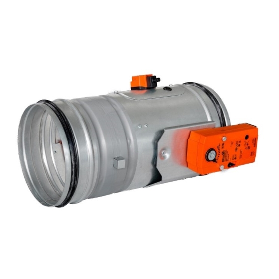
Mandik FDMR 60 Installation Instructions Manual
Fire damper
Hide thumbs
Also See for FDMR 60:
- Technical documentation manual (47 pages) ,
- Manual (46 pages) ,
- Installation instructions manual (35 pages)
Subscribe to Our Youtube Channel
Summary of Contents for Mandik FDMR 60
- Page 2 The FDMR 60 fire dampers were tested per EN 1366-2 and EN 15650. The fire dampers were classified per EN 13501-3 + A1: ↔ ≥ 100 ≥ 40 Fire damper FDMR Solid wall construction Mortar or gypsum Duct ≥ 100 ≥...
- Page 3 ≥ 100 Installation opening has to be reinforced by profile (UW, CW). Profil is fixed by screws ≥3,5 mm with cor- responding length. Distance between screws ≤200 mm. ≥ 40 Fire damper FDMR Gypsum plate Mineral wool Mortar or gypsum Duct ≥...
- Page 4 Fire damper FDMR Solid ceiling construction * min. 110 - Concrete/ min. 125 - Aerated Concrete Mortar or gypsum Duct ≥ 40 ≥ 50 Fire damper FDMR Solid ceiling construction Stuffing box (mineral stone wool min. density 140 kg/m³) Fire protection mastic min. thickness 1 mm Fibreglass felt with aluminium foil, * min.
- Page 6 During the installation process, the blade position must be “CLOSED”. During the installation process, the control mechanism must be protected against pollution and damage. Fire dampers are suitable for installation in any position in vertical and horizontal passages of fire separating structures.
- Page 7 The damper installation procedures must completely exclude any transfer of loads from the fire separating structure to the damper body. The connecting ducting must be suspended or supported in such a way that any transfer of load from the connecting duct to the damper flange is completely excluded. The damper body must not get deformed during its installation process.
- Page 8 Wiring diagrams N L1 S1 S2 <5° <80° S1 S2 <5° <80° 1(COM) - black wire 2(NC) - gray wire 4(NO) - blue wire AC 230V / 5A This limit switch is possible to connect in following two versions: IP 67 if the arm is moving …...
- Page 9 For dampers with mechanical control (designs .01, .11, .80) the following checks must be completed: The damper blade is turned to its “CLOSED” position as follows: • The damper is in its “OPEN” position. • By pressing the control mechanism button, you turn the damper into its “CLOSED” position. •...
- Page 10 • The damper bodies are normally supplied in their galvanized sheet steel design (alternatively stainless steel) without any additional surface finish. • The damper blades are made of asbestos-free fire-resistant mineral fibre boards. • The damper control devices are made of galvanized materials (alternatively of stainless steel) without any additional surface finish.
- Page 11 MANDÍK, a.s. Dobříšská 550 26724 Hostomice Czech Republic Tel.: +420 311 706 706 E-Mail: mandik@mandik.cz www.mandik.com The producer reserves the right for innovations of the product. For actual product information see www.mandik.com...


Need help?
Do you have a question about the FDMR 60 and is the answer not in the manual?
Questions and answers