Mandik FDMR 60 Technical Documentation Manual
Fire damper
Hide thumbs
Also See for FDMR 60:
- Manual (46 pages) ,
- Installation instructions manual (11 pages) ,
- Manual (29 pages)
Table of Contents
Advertisement
Quick Links
Advertisement
Table of Contents

Related Manuals for Mandik FDMR 60


Summary of Contents for Mandik FDMR 60
- Page 1 TPM 142/19 Version 2024-01-24 FDMR 60 Fire damper Technical Documentation Installation, Commissioning, Operation, Maintenance and Service Manual www.mandik.com MANDÍK, a. s. • Dobříšská 550 • 267 24 Hostomice • Czech Republic • Tel.: +420 311 706 742 • E-Mail: mandik@mandik.cz...
-
Page 2: Table Of Contents
TPM 142/19 These technical specifications state a row of manufactured sizes and models of fire dampers FDMR 60 It is valid for production, designing, ordering, delivery, maintenance and operation. CONTENT I. GENERAL.....................................3 Description....................................3 II. DESIGN.......................................4 Design with manual control..............................4 Design with spring return actuator............................6 Design with the communication and supply device......................9... -
Page 3: General
FDMR 60 with spring return actuator FDMR 60 with manual control Damper characteristics CE certified acc. to EN 15650 ■... -
Page 4: Design
■ ■ with two limit switches signaling of the damper blade Limit switch detail → see page 5 ■ position "CLOSED" and "OPEN". Limit switch Limit switch “OPEN” “CLOSED” Design .80 Page 4 Fire damper - FDMR 60 Version 2024-01-24... - Page 5 Class of protection IP 67 CUT-OFF if the arm is moving … connect wire 1+2 ■ Working temperature -25°C … +120°C SWITCH-ON if the arm is moving … connect wire 1+4 ■ Version 2024-01-24 Fire damper - FDMR 60 Page 5...
-
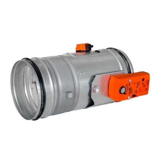
Page 6: Design With Spring Return Actuator
"OPEN" to the position "CLOSED" takes maximum 20 sec. Signalisation of damper blade position "OPEN" and ■ "CLOSE" is provided by two microswitches. Thermoelectric activation device BAT Spring return actuator Design .40 and .50 Page 6 Fire damper - FDMR 60 Version 2024-01-24... - Page 7 1 m, 2 x 0,75 mm² (BFL 2xx-T-ST) with 3-pin plug-in connectors - auxiliary switch cable 1 m, 6 x 0,75 mm² (BFL 2xx-T-ST) with 6-pin plug-in connectors duct outside temperature +72°C Response temperature thermal fuse duct inside temperature +72°C Version 2024-01-24 Fire damper - FDMR 60 Page 7...
- Page 8 Max. 95% RH, non-condensing Connection supply Cable 1 m, 2 x 0.5 mm², Betaflam cable heatresistant up to 145°C Duct inside temperature +72 (95/120/140)°C Response temperature thermal fuse Duct outside temperature +72 (95/120/140)°C Page 8 Fire damper - FDMR 60 Version 2024-01-24...
-
Page 9: Design With The Communication And Supply Device
Non-operating temperature -40°C … +80°C Connection - net cable 0,9 m with EURO plug type 26 - motor 6-pole connector, 3-pole connector - terminal board screw terminals for cable 2x1,5 mm² Version 2024-01-24 Fire damper - FDMR 60 Page 9... -
Page 10: Communication And Control Device Bks 24-1B And Bks 24-9A
Protection Class Degree of protection IP 30 Ambient temperature 0°C … +50°C 11-pole connector ZSO-11, it is not part of BKS24-1B, Connection ZSO-11 is 11-pole screw terminal 11 x 1,5 mm Page 10 Fire damper - FDMR 60 Version 2024-01-24... - Page 11 Nominal voltage AC 24 V 50/60Hz Power consumption 3,5 W Dimensioning 5,5 VA Protection Class Degree of protection IP 30 Ambient temperature 0°C … +50°C Connection terminal 2 x 1,5 mm Version 2024-01-24 Fire damper - FDMR 60 Page 11...
-
Page 12: Dimensions
Damper blade Inspection opening cover Sensor sticker Hole for camera Design with spring return actuator Damper casing Spring return actuator Damper blade Inspection opening cover Thermoelectric activation device BAT Hole for camera Page 12 Fire damper - FDMR 60 Version 2024-01-24... - Page 13 Values "a" has to be respected when projecting following air-conditioning duct. Fire damper with installation brackets Weight of the installation bracket is 0,04 kg. ■ Number of installation brackets for individual sizes → see page 14 ■ Version 2024-01-24 Fire damper - FDMR 60 Page 13...
-
Page 14: Technical Parameters
0,0275 0,0354 0,0462 0,0542 40,5 0,0606 0,0751 60,4 0,0776 0,1015 Weight of an installation bracket is 0,04 kg. ** For designs with BKN a weight of 0.5 kg must be added. Page 14 Fire damper - FDMR 60 Version 2024-01-24... -
Page 15: Installation
X = recommended min. distance for manual control ≥ 250 mm Y = min. distance for actuator ≥ 200 mm acc. to EN 1366-2 Y = recommended min. distance for manual control ≥ 250 mm Version 2024-01-24 Fire damper - FDMR 60 Page 15... - Page 16 100 mm. Outside the wall/ceiling contruction. The duct and ■ damper must be protected by fire insulation. Gypsum wall construction with minimum thickness ■ 100 mm. Page 16 Fire damper - FDMR 60 Version 2024-01-24...
-
Page 17: Statement Of Installations
110 - Concrete ISOVER Ultimate Protect - mortar or gypsum (damper under ceiling) Outside solid ceiling construction 125 - Aerated ISOVER Ultimate Protect - mortar or gypsum (damper above ceiling) concrete Version 2024-01-24 Fire damper - FDMR 60 Page 17... -
Page 18: Installation In Solid Wall Construction
For connection of following duct → see page 38 ■ ≥ 100 FDMR 60 Solid wall construction Mortar or gypsum Clamp with threaded rod → see pages 35 to 37 Duct Page 18 Fire damper - FDMR 60 Version 2024-01-24... - Page 19 Fire stop coating - th. 1 mm (HILTI CFS-CT...) - coating is overcoated on the support construction and on the damper casing/duct Fire-resistant mastic - (HILTI CFS-S ACR...) fill the gap from both sides of the fire separation construction and around the perimeter of penetration and damper casing Version 2024-01-24 Fire damper - FDMR 60 Page 19...
- Page 20 ≥ 100 ⑤ ≥ 150 FDMR 60 Solid wall construction Solid ceiling construction Mortar or gypsum Mineral wool board - min. density 140 kg/m (e.g. PROMAPYR-T150, ROCKWOOL HARDROCK / STEPROCK HD) Page 20 Fire damper - FDMR 60 Version 2024-01-24...
- Page 21 → see page 38 ■ Conditions of this installation are also valid for the installation in Solid ceiling construction ■ ≥ 100 FDMR 60 Solid wall construction Solid ceiling construction Mortar or gypsum Version 2024-01-24 Fire damper - FDMR 60 Page 21...
-
Page 22: Installation Outside Solid Wall Constrution
Fire stop coating - th. 1 mm (HILTI CFS-CT...) - coating is overcoated on the support construction and on the damper casing/duct Fire-resistant mastic - (HILTI CFS-S ACR...) fill the gap from both sides of the fire separation construction and around the perimeter of penetration and damper casing Page 22 Fire damper - FDMR 60 Version 2024-01-24... -
Page 23: Installation In Gypsum Wall Construction
For connection of following duct → see page 38 ■ ≥ 100 FDMR 60 Gypsum wall construction Mortar or gypsum Clamp with threaded rod → see pages 35 to 37 Duct Version 2024-01-24 Fire damper - FDMR 60 Page 23... - Page 24 Fire stop coating - th. 1 mm (HILTI CFS-CT...) - coating is overcoated on the support construction and on the damper casing/duct Fire-resistant mastic - (HILTI CFS-S ACR...) fill the gap from both sides of the fire separation construction and around the perimeter of penetration and damper casing Page 24 Fire damper - FDMR 60 Version 2024-01-24...
- Page 25 ≥ 100 ⑤ ≥ 150 FDMR 60 Gypsum wall construction Solid ceiling construction Mortar or gypsum Mineral wool board - min. density 140 kg/m (e.g. PROMAPYR-T150, ROCKWOOL HARDROCK / STEPROCK HD) Version 2024-01-24 Fire damper - FDMR 60 Page 25...
- Page 26 → see page 38 ■ Conditions of this installation are also valid for the installation in Solid ceiling construction ■ ≥ 100 FDMR 60 Gypsum wall construction Solid ceiling construction Mortar or gypsum Page 26 Fire damper - FDMR 60 Version 2024-01-24...
-
Page 27: Installation Outside Gypsum Wall Constrution
Fire stop coating - th. 1 mm (HILTI CFS-CT...) - coating is overcoated on the support construction and on the damper casing/duct Fire-resistant mastic - (HILTI CFS-S ACR...) fill the gap from both sides of the fire separation construction and around the perimeter of penetration and damper casing Version 2024-01-24 Fire damper - FDMR 60 Page 27... -
Page 28: Installation In Sandwich Wall Construction
Fire stop coating - th. 1 mm (HILTI CFS-CT...) - coating is overcoated on the support construction and on the damper casing/duct Fire-resistant mastic - (HILTI CFS-S ACR...) fill the gap from both sides of the fire separation construction and around the perimeter of penetration and damper casing Page 28 Fire damper - FDMR 60 Version 2024-01-24... -
Page 29: Installation Outside Sandwich Wall Construction
Fire stop coating - th. 1 mm (HILTI CFS-CT...) - coating is overcoated on the support construction and on the damper casing/duct Fire-resistant mastic - (HILTI CFS-S ACR...) fill the gap from both sides of the fire separation construction and around the perimeter of penetration and damper casing Version 2024-01-24 Fire damper - FDMR 60 Page 29... -
Page 30: Installation In Shaft Wall Construction
Fire stop coating - th. 1 mm (HILTI CFS-CT...) - coating is overcoated on the support construction and on the damper casing/duct 10 Fire-resistant mastic - (HILTI CFS-S ACR...) fill the gap from both sides of the fire separation construction and around the perimeter of penetration and damper casing Page 30 Fire damper - FDMR 60 Version 2024-01-24... -
Page 31: Installation In Solid Ceiling Construction
FDMR 60 Solid ceiling construction Mortar or gypsum Clamp with threaded rod → see pages 35 to 37 * min. 110 mm - Concrete min. 125 mm - Aerated concrete Duct Version 2024-01-24 Fire damper - FDMR 60 Page 31... - Page 32 Fire stop coating - th. 1 mm (HILTI CFS-CT...) - coating is overcoated on the support construction and on the damper casing/duct Fire-resistant mastic - (HILTI CFS-S ACR...) fill the gap from both sides of the fire separation construction and around the perimeter of penetration and damper casing Page 32 Fire damper - FDMR 60 Version 2024-01-24...
-
Page 33: Installation Outside Solid Ceiling Constrution
Standard air duct, made of galvanized sheet metal min. thickness 0,8 mm ISOVER Protect BSK glue - apply on the insulation and fix it to the fire separation construction Clamp with threaded rod → see pages 35 to 37 Version 2024-01-24 Fire damper - FDMR 60 Page 33... - Page 34 Standard air duct, made of galvanized sheet metal min. thickness 0,8 mm ISOVER Protect BSK glue - apply on the insulation and fix it to the fire separation construction Clamp with threaded rod → see pages 35 to 37 Page 34 Fire damper - FDMR 60 Version 2024-01-24...
-
Page 35: Suspension Systems
Washer for M8 - M20 Coupling Nut M8 - M20 84,3 Anchor Hinge plate - min. thickness 10 mm Concrete screw tested for fire resistance R30-R90, max. Tension up to 0.75 KN (length 35 mm) Version 2024-01-24 Fire damper - FDMR 60 Page 35... - Page 36 TPM 142/19 Example of fixing FDMR 60 to the wall or ceiling In solid wall construction In solid ceiling construction In gypsum wall construction Ø100–400 t(mm): 1,5 Ø100–400 Quick closing system 2x screw M6×20. Fixing nut for threaded rod M8.
- Page 37 TPM 142/19 Example of fixing FDMR 60 outside the wall or ceiling Outside solid wall construction Outside solid ceiling construction Outside gypsum wall construction Ø100–400 t(mm): 1,5 Ø100–400 Solid wall construction Quick closing system Solid ceiling construction 2x screw M6×20.
-
Page 38: Example Of Duct Connection
1 FDMR 60 2 Duct 3 Extension piece (if required) 4 Damping pad 5 Bolt assembly M8 (bolt M8x20 mm, 2 pcs large washer M8, nut M8) 6 Protective bonding conductor Page 38 Fire damper - FDMR 60 Version 2024-01-24... -
Page 39: Technical Data
Determination of pressure loss by using diagram ρ = 1,2 kg/m air flow speed w [m/s] Coefficient of local pressure loss ξ 2,736 2,099 1,781 1,527 1,272 0,929 0,636 0,892 0,747 0,627 0,576 0,531 0,471 0,455 0,393 Version 2024-01-24 Fire damper - FDMR 60 Page 39... -
Page 40: Noise Data
-24,1 -33,2 -5,2 -3,9 -4,3 -6,4 -10,1 -15,6 -22,7 -31,5 -5,5 -4,1 -5,9 -9,4 -14,6 -21,5 -5,9 -4,1 -5,6 -8,9 -13,8 -20,4 -28,8 -6,2 -4,3 -3,9 -5,3 -8,4 -13,1 -19,5 -27,6 Page 40 Fire damper - FDMR 60 Version 2024-01-24... -
Page 41: Material, Finishing
The damper blade in the variant for chemical environments (Class A4) is always treated with a coating of chemically resistant Promat SR. Any other requirements for the design will be considered atypical and will be addressed on an individual basis. Version 2024-01-24 Fire damper - FDMR 60 Page 41... -
Page 42: Transportation, Storage And Warranty
The warranty for fire dampers FDMR 60, provided by the ■ are mechanically damaged during handling. manufacturer, is completely void if actuating, closing and... -
Page 43: Assembly, Attendance And Maintenance
Once the damper is built in, the damper blade shall not ■ ■ bricking in. grind on the damper casing during opening or closing. Protection of the damper casing against buckling during installation. WRONG! Brace with wooden blocks Brace with wedges Version 2024-01-24 Fire damper - FDMR 60 Page 43... -
Page 44: Commissioning And Revisions
Removing the thermal fuse from the fuse holder of a manual control, checks its correct functionality. ■ The manual control is identified as M1 to M5, depending on the closing spring strength. ■ Page 44 Fire damper - FDMR 60 Version 2024-01-24... - Page 45 If the thermal fuse Tf2 is interrupted (due to temperature inside the duct) , only the spare part ZBAT 72 (95/120/140) needs ■ to be replaced (acc.to the activation temperature). → see page 8 Version 2024-01-24 Fire damper - FDMR 60 Page 45...
-
Page 46: Ordering Informations
SL - spiro damper SK - spiro damper with installation brackets EXAMPLE: FDMR 60 SL 200 .40 - SL - spiro damper, 200 - damper diameter, .40 - design Damper design Additional digit Manual control and thermal Manual control and thermal with a terminal switch („CLOSED“) Manual control and thermal with two terminal switches („OPEN“, „CLOSED“) - Page 47 The producer reserves the right for innovations of the product. For actual product information see www.mandik.com www.mandik.com MANDÍK, a. s. • Dobříšská 550 • 267 24 Hostomice • Czech Republic • Tel.: +420 311 706 742 • E-Mail: mandik@mandik.cz...
Need help?
Do you have a question about the FDMR 60 and is the answer not in the manual?
Questions and answers