Table of Contents
Advertisement
Quick Links
420-0036-01UK
2
PRINTING
nd
Sega Amusements International Limited.
42 Barwell Business Park, Leatherhead Road, Chessington, Surrey, KT9 2NY. United Kingdom.
Telephone: +44 (0) 208 391 8090
Facsimile:
+44 (0) 208 391 8099
email: sales@segaarcade.com
Web: http://www.segaarcade.com
© SEGA
Errors & Omissions Excepted (E&OE)
amusements international
IMPORTANT
• Before using this product, read this manual carefully to understand the
contents herein stated.
• After reading this manual, be sure to keep it near the product or in a
convenient place for easy reference when necessary.
amusements international
Advertisement
Table of Contents

Related Manuals for Sega MISSION: IMPOSSIBLE


Summary of Contents for Sega MISSION: IMPOSSIBLE
- Page 1 420-0036-01UK PRINTING Sega Amusements International Limited. 42 Barwell Business Park, Leatherhead Road, Chessington, Surrey, KT9 2NY. United Kingdom. Telephone: +44 (0) 208 391 8090 Facsimile: +44 (0) 208 391 8099 email: sales@segaarcade.com Web: http://www.segaarcade.com IMPORTANT © SEGA • Before using this product, read this manual carefully to understand the contents herein stated.
- Page 2 BEFORE USING THE PRODUCT, BE SURE TO READ THE FOLLOWING: To maintain safety: To ensure the safe operation of this product, be sure to read the following before usage: The following instructions are intended for the users, operators and the personnel in charge of the operation of the product.
- Page 3 SEGA shall not be held responsible for any accidents or compensation for damage to a third party resulting from the specifications not designated by SEGA • Ensure that the product meets the requirements of appropriate electrical...
- Page 4 Indicates a warning or caution that, if ignored, may result in the mishandling of the product and cause faulty operation or damage to the product Sega Amusements International Limited amusements international 42 Barwell Business Park, Leatherhead Road,...
- Page 5 Definition of 'Site Maintenence Personnel’ or Other Qualified Individuals Definition of 'Site Maintenence Personnel’ or Other Qualified Individuals Procedures not described in this Manual or marked as ‘to be carried out by site maintenance personnel or other qualified professionals’ should not be carried out by personnel without the necessary skill or technological experience. Work carried out by unqualified persons may cause serious accidents, including electrocution.
- Page 6 The symbol shown below will be placed on all products manufactured from 13th August 2005, which indicates this product must NOT be disposed of with other normal waste. Upon purchasing any EEE from SEGA Amusements International Ltd. The user accepts responsibility to dispose of their waste equipment by arranging to return it to a designated UK collection point (AATF) or an Approved Exporter (AE) for the correct recycling of waste electrical and electronic equipment.
- Page 7 LIST OF 3rd PARTY RIGHTS _____________________________________________ Copyright (C) 1994-2008 Lua.org, PUC-Rio. Permission is hereby granted, free of charge, to any person obtaining a copy of this software and associated documentation files (the “Software”), to deal in the Software without restriction, including without limitation the rights to use, copy, modify, merge, publish, distribute, sublicense, and/or sell copies of the Software, and to permit persons to whom the Software is furnished to do so, subject to the following conditions: The above copyright notice and this permission notice shall be included in all copies or substantial portions of the Software.
-
Page 8: Table Of Contents
TABLE OF CONTENTS INTRODUCTION HANDLING PRECAUTIONS PRECAUTIONS REGARDING INSTALLATION PRECAUTIONS REGARDING OPERATION 3-1 Before Operation 3-2 Paying Attention to Customers PARTS DESCRIPTION ACCESSORIES ASSEMBLY AND INSTALLATION 6-1 Installing the Floor 6-2 Installing the Rear Header 6-3 Installing the Box Fuse 6-4 Fixation to Site 6-5 Confirmation of Installation 6-6 Components that Change State 6-7 Linking Multiple Cabinets... - Page 9 COIN HANDLING 12-1 Cleaning the Coin Selector 12-2 Fault Finding 12-3 Adjusting the Price of Play (Excel) 12-4 Coin Region & Price of Play Settings 12-5 Price of Play Quick Start (USA) LAMPS AND LIGHTING 13-1 Coin Door Lamp 13-2 Cabinet LED List 13-3 LED Diagrams 13-4 Lighting Removal Procedures PERIODIC INSPECTION...
-
Page 10: Handling Precautions
• SEGA shall not be held responsible for damage or compensation for damage to a third party caused by specification changes not designated by SEGA •... - Page 11 • Some parts are not designed or manufactured specifically for this game machine. The manufacturers may discontinue or change the specifications of such general-purpose parts. If this is the case, SEGA cannot repair or replace a failed game machine whether or not a warranty period has...
- Page 12 CONCERNING THE STICKER DISPLAY This SEGA product has stickers attached describing the product manufacture No. (Serial No.) and Electrical Specifications. It also has a Sticker describing where to contact for repair and for purchasing parts. When inquiring about or asking for repairs, mention the Serial No. and Name of Machine indicated on the Sticker.
- Page 13 BASS SHAKER LB1219 LB1219 VOLUME LB1218 LB1218 CAUTION CAUTION If you or your child have experienced a convulsive attack, loss of consciousness, etc., due to light stimulus or TV game, or fear that you may experience such symptoms, be very careful of using this machine.
-
Page 14: Precautions Regarding Installation
PRECAUTIONS REGARDING INSTALLATION • This product is an indoor game machine. Do not install it outside. Even indoors, avoid installing in places mentioned below so as not to cause fire, electric shock, injury and/or malfunction: • Places subject to rain/water leakage or places subject to high humidity, in the proximity of an indoor swimming pool and/or shower, etc •... - Page 15 2.56m (100.7in) in depth when the cabinet is installed. SEGA shall not be held responsible for damage or compensation for damage to a third party, resulting from the failure to observe this instruction • The ceiling where this product is installed must be at least 2.75m (109in)
- Page 16 • To install this product, the entrance must be at least 1.2m (47.2in) in width and 2.75m (109in) in height with Billboard and 2.03m (79.9in) without Billboard. If the entrance is too narrow, do not tilt the product carelessly. If all the product weight is put on the casters at one side only, there could be damage or deformation, causing serious accidents such as workers getting caught underneath...
-
Page 17: Precautions Regarding Operation
PRECAUTIONS REGARDING OPERATION To avoid injury and trouble, be sure to pay attention to the behaviour of visitors and players. 3-1 BEFORE OPERATION • In order to avoid accidents, check the following before starting the operation: • To ensure maximum safety for the players and the customers, ensure that where the product is operated has sufficient lighting to allow any warnings to be read. - Page 18 • To avoid injury, be sure to provide sufficient space by considering the potentially crowded situation at the installation location. Insufficient installation space can cause contact, collisions, and/or trouble between customers • During daily cleaning, be sure to check the surface of the control unit and other parts that the player touches with his/her hands for damage, cracks, or loose screws.
-
Page 19: Paying Attention To Customers
3-2 PAYING ATTENTION TO CUSTOMERS To avoid injury and trouble, be sure to constantly give careful attention to the behaviour and manner of the visitors and players. DURING OPERATION (PAYING ATTENTION TO CUSTOMERS) • For safety reasons, do not allow any of the following people to play the game: Those who have high blood pressure or a heart problem Those who have experienced muscle convulsion or loss of consciousness when playing video games, etc. - Page 20 ● Diligently clean the parts that players touch directly to ensure a pleasant game playing experience ● Inspect the coin insertion slots to make sure no foreign objects have been inserted and that they have not otherwise been tampered with as this will prevent play •...
-
Page 21: Parts Description
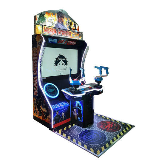
PART DESCRIPTIONS Rear Header Front Panel Header and Fuse Box Speakers Monitor Control Units Coin Tower Floor... -
Page 22: Accessories
ACCESSORIES Confirm that the accessories listed in the table below are present when setting up the product. Accessories marked “Spare” are consumable items but included as spares. Part Name / Number Diagram Quantity Owner’s Manual (Part #: 420-0036-01UK) Master Key (J9117) Security Key (A444) Power Lead UK (Pt No LM1227) EU (Pt No LM1246) -
Page 23: Assembly And Installation
ASSEMBLY AND INSTALLATION ● Perform assembly work by following the procedure herein stated. Failure to comply with the instructions can cause electric shock ● Perform assembling as per this Manual. Since this is a complex machine, incorrect assembling can cause an electric shock, machine damage and/or improper functioning as per specified performance ●... - Page 24 ● Handle molded parts with care. Excessive weight or pressure may cause them to break and the broken pieces may cause injury ● To perform the operation safely and accurately you must use a safe, steady footstool or stepladder. Working without this may lead to a fall and possible injury ●...
-
Page 25: Installing The Floor
6-1 INSTALLING THE FLOOR Unlock and remove the Door Back Lower with the supplied keys Unlock with Key Slide the Assy Floor Panel (MI-9000XUK) into position and align with the Monitor Cab. Remove the (2) M4 fixings on the Bracket Endcap LED Edging Lower L/R (MI-7009XUK/MI-7010XUK) and move them into the lower installation position shown. - Page 26 Remove the (2) internal fixings on either side of the Coin Tower to release it. Slide the Coin Tower roughly half way out. Lift the Coin Tower over the Bass Shaker and extend fully. Reapply the (2) previously removed fixings into the fixing points shown to secure the Coin Tower in place Internal Fixing (one each side) Pull Coin Tower half way and lift over Bass Shaker...
- Page 27 Feed harnessing through the hole in the Bracket Floor Cable (MI-7011UK) and make the harnessing connections to the Bass Shaker and Floor Bracket Floor Cable (MI-7011UK) Feed harnessing through Connect the Harnesses from the Monitor Cab to the Coin Tower Secure the (8) M6X30 fixings on the Bracket Cover Joint Ctrl Cabi (MI-7059XUK)
- Page 28 Secure the (8) M6 fixings on the Bracket Floor Locating LH (HDZ-9003XUK) and perform the same procedure on the RH side Secure the (4) M6 fixings on the Bracket Floor Locating Mid (MI-9006XUK)
-
Page 29: Installing The Rear Header
6-2 INSTALLING THE REAR HEADER ● Installing elements of the Installation Kit require the use of stepladders and/or equipment allowing the people installing the cabinet to work at height ● It is recommended to carry out this part of the installation with a minimum of at least 2 people Remove the (5) M6 highlighted fixings and the (2) M4 fixings... - Page 30 Insert the Panel Rear Header Artwork (MI-5722X-AUK) and secure using the (3) M4 highlighted fixings Insert Strutt Sup Header Front (MI-5701XUK) into positon on the right hand side and apply the (2) M6 highlighted fixings Perform the same procedure on the left hand side...
-
Page 31: Installing The Box Fuse
Insert the Bracket Cross Supp Header Mid (MI-5702XUK) and secure using the (2) M4 highlighted fixings Insert the Panel Header Mid Artwork (MI-5712X-AUK) and secure using the (3) M4 highlighted fixings 6-3 INSTALLING THE BOX FUSE Insert Assy Box Fuse MKII (MI-5735XUK) into position shown. Remove highlighted M6 fixings from situ and reapply to secure Box Fuse... - Page 32 Connect the harnessing from the Box Fuse to the Monitor Cabinet. Connect the harnessing on the Bracket Cross Supp Header Mid to the connection on the Rear Header Cross Supp Header Mid connection Fuse Box connection Insert the Panel Header Front Artwork (MI-5711X-AUK) and secure using the (2) M4 highlighted fixings...
-
Page 33: Fixation To Site
6-4 FIXATION TO INSTALLATION SITE Make sure that all the adjusters contact the floor. Otherwise the cabinet could move, causing an accident The product comes with castors attached at 5 locations and adjusters at 4 locations. When the installation site has been determined, have the adjusters come in direct contact with the floor. Establish a gap of about 5 mm between the floor and the castors and adjust the unit so that it will remain level. - Page 34 CONNECTION OF POWER AND GROUND CABLES (Only applies where an integral earth is not present in the mains/power lead) ● Use the power supply equipped with an earth leakage breaker. Use of power supply without such a breaker could result in fire if there is a current leakage ● Have available a securely grounded indoor ground terminal. Without proper grounding, customers could be electrocuted and product operations might not always be stable ●...
-
Page 35: Confirmation Of Installation
6-5 CONFIRMATION OF INSTALLATION Use test mode to confirm that assembly is proper, connecting boards, and input/output devices are normal. See Section 9 “Test and Service Data” for more information on each individual test. Perform the following tests in test mode: Unlock and open the Coin Door to access the SW Unit. Use the Test Button to enter the Test and Service Menu SW Unit Enter the section “Input Test”. -
Page 36: Components That Change State
6-6 COMPONENTS THAT CHANGE STATE UPON POWERING UP Panels illuminate Game powers on Audio from speakers Control Panel illuminates Floor edges illuminate... -
Page 37: Linking Multiple Cabinets
6-7 LINKING MULTIPLE CABINETS It is important that a suitable location is secured to enable installation to be carried out safely. Please refer the beginning of this Manual for Operational Area. This will show the procedure for installing (2) cabinets. It is only possible for two Cabinets to be linked. Place (2) Cabinets into position. - Page 38 When powering the machine on for the first time, be sure NOT to have the network cables connected. Having the network cables connected when powering up for the first time will cause a network malfunction and incorrect IP addresses will be assigned Apply power to the Cabinets and enter the TEST menu using the TEST SW located behind the coin door on the credit board (on both Cabinets)
-
Page 39: Precautions When Moving
PRECAUTIONS WHEN MOVING 7-1 MOVING THE MACHINE ● Always disconnect the power cable before moving the product. If it is moved with the power cable connected, the cable could be damaged, causing fire or electric shock ● To move the unit over the floor, pull in the adjustors and have the castors contact the floor. - Page 40 ● When moving the cabinet, do not hold, push, or pull the Control Units. This may disfigure or damage them ● If you need to move components through an awkward space and/or a separation method other than those described in this Manual is required, either make a request to the office listed in this document or the place of purchase to perform the operation or contact them regarding how to perform it.
-
Page 41: Game Description
GAME DESCRIPTION 8-1 GAME OUTLINE After the coins are inserted, available Credits will display at the bottom of the screen. After required coins are inserted, the text will change from “PLEASE INSERT COINS” into “PRESS START BUTTON”. The start button on the Cabinet will then be flashing. Coin system can accumulate up to 24 Credits. - Page 42 Players will then have to select their mission, each one consisting of three levels. Players will be given a short debrief of the chosen mission. During this time, they will also be shown that they are competing against a rival team of Agents. Their goal is to be the first team to complete the mission.
- Page 43 During the missions, Players will have to defeat enemies on the way to their goal. They will also have to complete various Quick-Time Events (QTEs) along the way. Some of these QTEs require the player(s) to press their button as fast as possible to fill up the ring to complete the action.
- Page 44 At the end of each level within a mission, Players will be given a report of their progress and how they compare with the rival Agent team or each other (if no Player team was present). They will be given an overall mission report after all levels are complete. After a mission has been completed, Players can choose to play another mission.
-
Page 45: Test And Service Data
TEST AND SERVICE DATA Do not touch any parts that are not specified in these directions. Touching unspecified locations may lead to electric shock or cause short circuits ● Be careful that your finger or hand does not get caught when opening/closing the coin chute door ●... -
Page 46: Switch And Coin Meter
9-1 SWITCH UNIT AND COIN METER The Switch Unit and Counter are housed within the Coin Tower. To access these controls you will need to open the Coin Door. The switches and counters can be found directly on the rear face of the Tower. COIN IN COUNTER CREDIT BOARD BASS SHAKER CONTROL VOLUME CONTROL... -
Page 47: Game Test Mode
9-2 GAME TEST MODE This is the main Test Mode menu. Here you can access a number of different sub menus to test different aspects of the Cabinet to ensure they are all working correctly. Use Service to cycle through items. Use Test to select an item and view that item's sub-menu. Select EXIT to return to Game. System Information Displays software and hardware version numbers Input Test... -
Page 48: System Information
9-3 SYSTEM INFORMATION This menu displays information about the Cabinet specs and hardware. Use the Service button to cycle through the options and the Test button to select an option. Game Name Name of installed game software Game Version Game software version number Disk Image Version Disk Image version of Game Board Launcher Version... -
Page 49: Input Test
9-4 INPUT TEST This menu tests the input function of controllers and coin. Note: Press the Test and Service Button together at the same time to exit this menu. Player 1 Controller X Shows co-ordinates of P1 Controller X Axis Player 1 Controller Y Shows co-ordinates of P1 Controller Y Axis Player 1 Controller Trigger L ON = P1 Controller Trigger L Pressed - OFF = Not Pressed Player 1 Controller Trigger R... -
Page 50: Output Test
9-5 OUTPUT TEST This menu tests the output function of lighting, controllers, and speakers. Player 1 Start Lamp ON = P1 Start Lamp illuminated - OFF = P1 Start Lamp off Player 2 Start Lamp ON = P2 Start Lamp illuminated - OFF = P2 Start Lamp off Cabinet Lighting (CTR/ Test event and game lighting (ATTRACT - GAME - EVENT - OFF) Woofer/Edge) -
Page 51: Calibration Test
9-6 CALIBRATION TEST This menu allows you to calibrate the control units. Player 1 Controller X Positional value of P1 X axis Player 1 Controller Y Positional value of P1 Y axis Player 2 Controller X Positional value of P2 X axis Player 2 Controller Y Positional value of P2 Y axis P1 Controller Min X Max X Minimum and maximum values P1 X values can be P1 Controller Min Y Max Y... -
Page 52: Coin Test
9-7 COIN TEST This menu allows you to see the total amount of credits and set the coin to credit ratio. Coin Count Amount of Coins the Cab has received Credits Amount of standard Credits the Cab has received Service Credits Amount of Service Credits the Cab has received Game Cost Set Cost of Game from Attract... -
Page 53: Sound Test
9-8 SOUND TEST This menu allows you to test the speaker, woofer, and bass shaker. You can also set the volume level for the attract mode. Audio in Attract Set volume of Attract video (FULL - 3/4 - 1/2 - 1/4 - OFF) Speaker Test Test Speaker function/noise level (ON = Speaker plays audio clip - OFF = No audio) -
Page 54: Screen Test
9-9 SCREEN TEST This menu allows you to adjust the screen variables like brightness and colour. Colour Bars: Brightness: Selecting this will display the following Selecting this will display the following screen: screen: Grid Alignment: Selecting this will display the following screen:... -
Page 55: Network Test
9-10 NETWORK TEST These menus allows you to test Cabinet networking Network Status Shows if Cab is successfully linked Cabinets Connected Shows the number of Cabinets connected Link Play Shows if Link Play is enabled (connected Cabs can still be isolated for Single Play) This Cab ID Displays Cab ID number Confirm Changes... -
Page 56: Bookkeeping
9-11 BOOKKEEPING These menus allows you to see Cabinet metrics and statistics. Coin Credits Amount of Coin Credits the Cab has received Service Credits Amount of Service Credits the Cab has received Total Credits Total amount of Credits the Cab has received Bookkeeping Last Cleared Date/Time stamp of the last time bookkeeping was cleared Hiscore Data Last Cleared... - Page 57 This menu shows the different types of games played and the min, max, and mean of Game time. Number of Games Amount of Coin Credits the Cab has received Number of Singleplay Amount of Service Credits the Cab has received First Play Total number of games started from Attract Continue Play Total number of Continues used Total Time...
- Page 58 This menus shows the historgam, which is a breakdown of the amount of time Games have ended, measured in 30 second increments. This menu shows the total continue ratios, amount of continues, and continues used on each mission. Total Continue Ratio Total Continue Ratio for all games Total Clear Ratio Total Clear Ratio (completing game from start to finish) Next Page...
-
Page 59: Clock Test
9-12 CLOCK TEST This menu allows you to set the internal Cabinet clock. Current Time Displays current time (24 Hour) Current Date Displays current Day/Month/Year Year Adjust Year Month Adjust Month Date Adjust Day Hour Adjust Hour (24 Hour) Minute Adjust Minute Second Adjust Second... -
Page 60: Game Assignments
9-13 GAME ASSIGNMENTS This menu allows you to adjust gameplay variables like language and difficulty. Language Change language of on-screen instructions (English - French - Spanish - Portuguese - Italian - Turkish) Game Difficulty Set difficulty of game (health of enemies) Revival Determines if both players can reach Game Over at the same time (multiplayer only) ON = One of two players will survive - OFF = Both players will Game Over P1 Controller Reaction... -
Page 61: Billboard Test
9-14 BILLBOARD TEST This menu allows you to evaluate the billboard connection Connection CONNECTED - Billboard is connected to Monitor Cab/Game Board - FAIL - Billboard connection error Mode Back Return to Main Test Menu... -
Page 62: Monitor
VIDEO DISPLAY The LCD display screen is adjusted prior to leaving the factory. Avoid any unnecessary adjustment ● If the adjustment method in this Manual does not resolve the problem, contact the customer service number in this Manual or your supplier ●... -
Page 64: Cleaning The Screen
10-2 CLEANING THE SCREEN ● Since the LCD display screen is susceptible to damage, pay careful attention to its handling. When cleaning, refrain from using water or volatile chemicals ● Do not climb onto the control panel. This could lead to injuries, such as bumping your head ●... -
Page 65: On-Screen Adjustment Method
10-3 ON SCREEN ADJUSTMENT METHOD (OSD) • If the adjustment method in this Manual does not resolve the problem contact the customer service number in this Manual or your supplier • Do not stick tape, stickers or anything else onto the screen. Any kind of adhesive may damage the surface of the screen •... - Page 66 OSD Main Menu - Adjustments The OSD Adjustment Main Menu is used for adjusting picture elements like Contrast and Brightness. OSD Main Menu - Feature Controls The OSD Feature Control Main Menu is used for changing mechanical elements like the Input Channel and Timer.
- Page 67 Item Description Contrast Adjusts the contrast level between different colours Brightness Adjusts overall brightness of picture Sharpness Adjusts edge to image contrast Color Temperature Adjust color temperature range User RGB Manually set levels of Red-Green-Blue display Impact Alignment Reset Revert settings to Factory Default Item Description Auto Color...
-
Page 68: Controller Unit
CONTROLLER UNIT • When working with the product, be sure to turn the power off. Working with the power on may cause an electric shock or short circuit • Be careful not to damage the wires. Damaged wires may cause an electric shock, short circuit or present a risk of fire •... -
Page 69: Replacing The Trigger Switch
11-1 REPLACING THE TRIGGER SWITCH Turn OFF the power to the machine and remove the Power cable Using a Torx Tamper proof key or driver, remove the (8) fixings from around the Right Hand outer face of the controller Torx Tamper Proof (8) Locate the Trigger Switch and carefully remove the (2) self tapping screws which retain the switch Self Tap Screws (2) Trigger Switch... - Page 70 Using a sharp knife or blade, carefully remove the protective sleeve from around the solder joint. Unsolder the ORG and BLK wires, taking note of their positionings Protective sleeves Solder joints Replace the switch and re solder the wires onto the new switch in their correct locations. Ensure that the protective sleeves are also replaced 1 - BLK 4 - ORG...
-
Page 71: Replacing The Controller I/O
11-2 REPLACING THE CONTROLLER I/O In instances whereby either or both controllers malfunction a possible cause is the GUN I/O PCB mounted beneath the center controller cover.. On the rare ocassions where the GUN I/O PCB fails, please follow these instructions for removal Turn OFF the power to the machine and remove the Power cable Remove the (4) Torx tamperproof fixings from both sides of the controller... -
Page 72: Replacing The Up/Down Sensors
11-3 REPLACING THE UP/DOWN SENSORS Turn OFF the power to the machine and remove the Power cable Remove the (4) Torx tamperproof fixings from both sides of the controller and lower the base cover Torx Tamperproof (2) Base Cover Remove the (2) machine screws which retain the cover bracket. This will enable you to gain access to the VERT Controller PCB Machine Screws (2) VERT Controller PCB... -
Page 73: Coin Handling
COIN HANDLING Handling the Coin Jam If the coin is not rejected when the REJECT button is pressed, open the coin chute door and open the selector gate. After removing the jammed coin, put a normal coin in and check to see that the selector correctly functions. 12-1 CLEANING THE COIN SELECTOR ●... - Page 74 CLEANING THE COIN SELECTOR (MECHANICAL) Remove and clean smears by using a soft cloth dipped in water or diluted chemical detergent and then squeezed dry. Remove the CRADLE. When removing the retaining ring (E ring) be very careful so as not to bend the rotary shaft. Remove stain from the rotary shaft and shaft CRADLE receiving portions by wiping off with a soft cloth.
- Page 75 CLEANING THE COIN SELECTOR (SR3 / NRI) Remove and clean smears by using a damp soft cloth dipped in water. DO NOT use any diluted chemical detergent or cleansing agent as this will impair the workings of the component. GATE Open the reject gate to gain access to the rundown path.
-
Page 76: Fault Finding
12-2 FAULT FINDING Fault Finding The following information is presented for customers’ guidance in rectifying a fault but does not cover all possible causes. All acceptors with electronic faults should be returned to an approved service centre for repair. SYMPTOM INVESTIGATE POSSIBLE CAUSE Poor Contact... -
Page 77: Adjusting The Price Of Play (Excel)
12-3 ADJUSTING THE PRICE OF PLAY (EXCEL) ● The price of play is determined by the configuration of switches located on either the EXCEL or VTS board. The type of board used is determined by product location. Switch settings for both types of board remain the same This product comes equipped with a Crane NRI Coin Acceptor. -
Page 78: Coin Region & Price Of Play Settings
12-4 COIN REGION & PRICE OF PLAY SETTINGS... - Page 79 Price of Play Settings (UK/EU) PRICE OF PLAY BONUS DIL SWITCH 1 0.10 0.10 0.50 = 6 credits 0.20 0.20 0.50 = 3 credits 0.30 0.30 1.00 = 4 credits 0.30 0.50 = 2 credits 0.30 1.00 = 3 credits 0.40 0.40 1.00 = 3 credits...
-
Page 80: Price Of Play Quick Start (Usa)
12-5 PRICE OF PLAY QUICK START - USA DIL SWITCH BANK ONE (5 way SW1) Item Price 25cent 50cent 75cent $1.00 $2.00 DIL SWITCH BANK TWO (6 way SW3) Type... -
Page 81: Lamps And Lighting
LAMPS AND LIGHTING • When working with the product, be sure to turn the power off. Working with the power on may cause an electric shock or short circuit • You may get burned by a hot fluorescent lamp or other lamps. Pay full attention to the lamps when performing the work •... -
Page 82: Cabinet Led List
13-2 CABINET LED LIST Related Assembly Lighting Part Assy # + Description MI-6504UK ASSY BILLBOARD SHORT MI-5720XUK Assy Box Rear Header MI-6503UK ASSY BILLBOARD LONG MI-6501UK ASSY FUSE SPARK LED MI-5735XUK Assy Box Fuse MKII MI-6502UK ASSY FUSE LED MI-6509UK ASSY CABINET EDGE MI-7000XUK Assy Monitor Cab MI-6510UK ASSY RGB LED WOOFER SAI-6101-1850UK ASSY LED RGB EP1510/EP1511 LED 10MM RED/BLUE CLUSTER 12V 161- 1 each... -
Page 83: Led Diagrams
13-3 LED DIAGRAMS 13-3-1 Assy Rear Header (MI-5720XUK) MI-6504UK MI-6503UK 13-3-2 Assy Box Fuse MKII (MI-5735XUK) MI-6501UK MI-6502UK 13-3-3 Assy Monitor Cab (MI-7000XUK) MI-6509UK MI-6510UK... - Page 84 13-3-4 Assy Control Panel (MI-7900XUK) MI-6004UK EP1511 EP1510 SAI-6101-1850UK (surrounds Ctrl Box) MI-6507UK 13-3-5 Assy Floor MI-6508UK...
-
Page 85: Lighting Removal Procedures
13-4 LIGHTING REMOVAL PROCEDURES 13-4-1 Woofer The following procedure describes the replacement of the LED within the WOOFER HOUSING. Remove the power from the machine and disconnect the mains input connector from the wall socket. Secure a space which allow for safe working conditions. Remove the (4) M4X16 SKT CAP BH BLK screws from the corners of the COVER LIGHTING M4X16 SKT CAP BH BLK [029-B00416-0B]... - Page 86 Open the Door Back Lower positioned behind the WOOFER speaker. Locate the harness to the ASSY LED WOOFER and disconnect. Disconnect Harness that comes through access hole Carefully pull the connector through the access point. Pull harness through access point Replace the ASSY LED WOOFER and reassemble following these steps in reverse order.
- Page 87 13-4-2 Control Panel The following procedure describes the replacement of the LED which edges the CONTROL PANEL. Remove the power from the machine and disconnect the mains input connector from the wall socket. Secure a space which allow for safe working conditions. Remove the (6) fixings from around the base of each controller as shown below.
- Page 88 Open the COIN DOOR and disconnect the BUTTON HARNESS. Carefully remove the CONTROL PANEL COVER. CONTROL PANEL COVER Open Coin Door Locate the LED FLEX RGB within a groove running along the outer edge of the CONTROL PANEL. Disconnect the WH RGB LONG. Carefully remove the LED FLEX RGB. WH RGB LONG [SAI-60001UK] LED FLEX RGB (1.85MTR)
- Page 89 13-4-3 Uplight The following procedure describes the replacement of the ASSY UPLIGHT [MI-6004UK]. The following procedure describes the replacement of the LED which edges the CONTROL PANEL. Remove the power from the machine and disconnect the mains input connector from the wall socket. Secure a space which allow for safe working conditions.
- Page 90 Open the COIN DOOR and disconnect the BUTTON HARNESS. Carefully remove the CONTROL PANEL COVER. CONTROL PANEL COVER Open Coin Door Locate the ASSY UPLIGHT [MI-6004UK] ASSY UPLIGHT [MI-6004UK] Disconnect the ASSY UPLIGHT, remove the Cable Ties which secure the ASSY UPLIGHT into position. Remove the ASSY UPLIGHT.
- Page 91 13-4-4 Downlight The following procedure describes the replacement of the ASSY DOWNLIGHT [MI-6003UK]. The following procedure describes the replacement of the LED which edges the CONTROL PANEL. Remove the power from the machine and disconnect the mains input connector from the wall socket. Secure a space which allow for safe working conditions.
- Page 92 Open the COIN DOOR and disconnect the BUTTON HARNESS. Carefully remove the CONTROL PANEL COVER. CONTROL PANEL COVER Open Coin Door Remove the (4) M4 NUT NYLOCK [050-U00400] which secure the LED MOUNT DOWNLIGHT LED MOUNT DOWNLIGHT [MI-1907UK] M4 NUT NYLOK PAS [050-U00400] Left hand controller has been removed for illustration purposes Carefully cut the Cable ties which secure the ASSY LED to the LED MOUNT.
-
Page 93: Periodic Inspection
PERIODIC INSPECTION The items listed below require periodic check and maintenance to retain the performance of this machine and to ensure safe business operation. When handling the controller, the player will be in direct contact with it. In order to always allow the player to enjoy the game, be sure to clean it regularly. - Page 94 Cleaning the Cabinet Surfaces When the cabinet surfaces are badly soiled, remove stains with a soft cloth dipped in water or diluted (with water) chemical detergent and squeezed dry. To avoid damaging surface finish, do not use solvents such as thinner, benzine, etc. other than ethyl alcohol, or abrasives, bleaching agent and chemical dustcloth. Some general-purpose household, kitchen and furniture cleaning products may contain strong solvents that degrade plastic components, coatings, and print.
-
Page 95: Troubleshooting
TROUBLESHOOTING 15-1 TROUBLESHOOTING (WHEN NO ERROR MESSAGE IS SHOWN) • This work should be performed by site maintenance personnel or other skilled professionals. Work performed by non-technical personnel can cause a severe accident such as an electric shock. If there are no Site Maintenance Personnel or other skilled professionals available, turn off the power immediately and contact the office given in this manual or from point of purchase •... - Page 96 Switch fault Replace switch work Start button does not light Lamp failure Replace lamp (Chapter 13-4-2) Stays on SEGA logo and Invalid Security Key does not go to advertise Contact point of purchase CPU error screen (error) Sights are not aligned due to...
- Page 97 The table above shows a list of possible failures and a brief solutions. If problems persist further or there are aditional issues which may not be listed here. Please contact you point of sale or the SEGA SERVICE department on...
-
Page 98: Game Board
GAME BOARD ● When working with the product, be sure to turn the power off. Working with the power on may cause an electric shock or short circuit ● Be careful not to damage the wires. Damaged wires may cause electric shock, short circuit or present a fire risk ●... -
Page 99: How To Remove Game Board
16-1 HOW TO REMOVE GAME BOARD The Game Board is located behind the Door Back Lower Centre (MI-1002-DUK). Turn off the power Locate Door Back Lower. Remove the (2) door release fixings, unlock with the Master Key and remove the door The Game Board is located inside in the bottom right corner... - Page 100 Disconnect all of the connectors connected to the Game Board (do not remove the Key Chip) Key Chip Carefully disconnect any and all connections to/from the Game Bd Unscrew the (4) M4 Phillips screws which secure the Game Board in place (2 on each side) M4 FIXINGS Lift and remove the Game Board from the cabinet.
-
Page 101: Design Related Parts
DESIGN RELATED PARTS For the warning display stickers, refer to Section 1. -
Page 102: Parts List
PARTS LIST MISSION IMPOSSIBLE DLX STRUCTURE FLOW MI-00002XUK TOP ASSY MISSION IMPOSSIBLE DX **** MI-7000XUK MI-7080XUK ASSY MONITOR CABINET ASSY AC UNIT MI-7200X-01UK MI-9000XUK ASSY 55 LED MAK861A3 DISPLAY ASSY FLOOR PANEL MONITOR OPTIONS MI-4500XUK MI-7200X-01UK MI-7200X-02UK ASSY ELEC BD UPPER ASSY 55 LED MAK861A3 DISPLAY ASSY 55 LED MAK867A2 DISPLAY MI-4600XUK... - Page 103 1 TOP ASSY MISSION IMPOSSIBLE DX (MI-00002XUK) ITEM NO PART NO DESCRIPTION MI-7000XUK ASSY MONITOR CABINET MI-9000XUK ASSY FLOOR PANEL 440-PL3000UK LABEL SUITE MI DLX 421-7988-91UK STICKER SERIAL NUMBER UK *101 220-5736-01 DFMD W/UNIV CRADLE&CASHBOX ENC HI SEC *103 OS1247 ALUMINIUM STICKY CLIP ASK-3 475-198 *401 MI-INST-X-DX ASSY INST MI DX *402...
- Page 104 2 ASSY SW UNIT (MI-1550UK) ITEM NO PART NO DESCRIPTION ****1 MI-1551UK BRKT SW USB DUAL METER+AMP ****101 838-14548-01UK SW & VOL CTL BD ****102 280-L00706-PM STANDOFF 6.4MM HOLE PM ****103 EP1380-01 CREDIT BOARD EXCEL ****104 220-5643UK COIN METER SMALL 12V ****105 OS1247 ALUMINIUM STICKY CLIP ASK-3 ****107 OS1098 CRIMP BELL END SMALL...
- Page 105 3 ASSY ELEC BD UPPER (MI-45000XUK) ITEM NO PART NO DESCRIPTION ***1 MI-4501XUK BOARD UPPER ELEC ***101 838-0043UK PCBA AMP 3CH ***102 838-0053UK LED DRIVER ATMEGA328 WOOFLY3 ***103 280-A012640-WX ROUTER TWIST D12 SO6.4 WOOD X ***104 838-0042UK ***105 OS1011 PCB FEET RICHCO LCBS-L-5-01 ***106 280-L00640-WX STANDOFF 6MM 4 HOLE WOOD XL BHL-8-01 ***201 012-P03512-F...
- Page 106 4 ASSY ELEC BD LOWER (MI-4600XUK) 202 203 ITEM NO PART NO DESCRIPTION ***1 MI-4601XUK BOARD LOWER ELEC ***101 400-150-05-04 PSU 5V 150W MW RSP-150-5 ***102 400-150-024-03 PSU 24V 150W MW RSP-150-24 ***103 400-320-012-01 PSU 12V 320W MW RSP-320-12 ***106 280-A012640-WX ROUTER TWIST D12 SO6.4 WOOD X ***202 029-B00416 M4X16 SKT BH PAS...
- Page 107 5 ASSY GAME BOARD DX (MI-4700XUK) 101 202 204 ITEM NO PART NO DESCRIPTION ***1 MI-4701XUK BASE GAMEBOARD ***5 LB1111 STICKER PLEASE RECYCLE ***101 610-0014-01UK ASSY PC MI ***102 EP3002-03PU DK MI PUR ***103 280-A012640-WX ROUTER TWIST D12 SO6.4 WOOD X ***104 LB1101 STICKER WARNING BATTERY ***202 029-B00416 M4X16 SKT BH PAS...
- Page 108 6 ASSY BOX REAR HEADER DX (MI-5720XUK) 202 203 204 ITEM NO PART NO DESCRIPTION ***1 MI-5721XUK PNL HEADER BACKBOARD ***2 MI-5722XUK PNL HEADER REAR ***3 MI-5723XUK BRKT MTG SIDE ***4 MI-5724XUK BRKT BACK REAR HEADER ***5 MI-5725XUK BRKT SUPP HEADER MID ***101 280-L01030-OS STANDOFF 10OD 5.21D 30L RRSN-52100-30 ***102 OS1249 P CLIP 6.5MM...
- Page 109 7 ASSY FUSE BOX MK II (MI-5735XUK) ITEM NO PART NO DESCRIPTION ***1 MI-5736XUK BOX LIGHT MTG MKII ***3 MI-5738XUK BRKT MTG BOX FUSE MKII ***101 601-0460 CABLE TIE 100MM ***201 000-F00306 M3X6 MSCR CSK PAS ***202 029-B00412 M4X12 SKT BH PAS ***203 068-441616 M4 WSHR 16OD FLT PAS ***204 029-B00612 M6X12 SKT BH PAS...
- Page 110 8 ASSY MONITOR CAB (MI-7000XUK) (D-1/2) 23 201 202 204 205 206 207 208 Part 15 Brkt Floor Cable MI-7011XUK ITEM NO PART NO DESCRIPTION HDZ-1010XUK ASSY MONITOR FAN MI-7080XUK ASSY AC UNIT MI-7200X-01UK ASSY 55 LED MAK861A3 DISPLAY MI-4500XUK ASSY ELEC BD UPPER MI-4600XUK ASSY ELEC BD LOWER MI-4700XUK...
- Page 111 8 ASSY MONITOR CAB (MI-7000XUK) (D-2/2) ITEM NO PART NO DESCRIPTION **201 029-B00425-0B M4X25 SKT BH BLK **202 060-S00400-0B M4 WSHR SPR BLK **203 060-F00400 M4 WSHR FORM A FLT PAS **204 068-441616-0B M4 WSHR 16OD FLT BLK **205 029-B00625 M6X25 SKT BH PAS **206 068-652216 M6 WSHR 22OD FLT PAS...
- Page 112 9 ASSY AC UNIT (MI-7080XUK) ITEM NO PART NO DESCRIPTION ***1 DA-1081UK PLATE AC ***2 TFF-0402UK CONN COVER ***101 EP1302 EUROSOCKET FUSED 10A 250VAC ***102 514-5078-3150 FUSE 3.15 X 20 CERAMIC SB 3150mA ***103 SW1109 SWITCH ROCKER 250V AC ***104 EP1419 FILTER SCHAFFNER 2030-16-06 ***107 EP1391 COUPLER INLINE LAN RJ45...
- Page 113 10 ASSY 55 LED MAK861A3 DISPLAY (MI-7200X-01UK) ITEM NO PART NO DESCRIPTION ***1 MI-7201X-01UK BRKT SUPP MON ***101 200-6055-01-MV 55" CASED BLUE ***201 029-B00612 M6X12 SKT BH PAS ***202 068-652016 M6 WSHR 20OD FLT PAS ***203 060-S00600 M6 WSHR SPR PAS ***301 MI-65020UK WH DISPLAY M/V...
- Page 114 11 ASSY CTRL CABINET (MI-7500XUK) 201 202 203 204 209 208 ITEM NO PART NO DESCRIPTION ***1 MI-7502XUK ASSY CABI MID DX ***2 MI-7900XUK ASSY CTRL BOX DX ***3 MI-1550UK ASSY SW UNIT ***5 MI-7504XUK BRKT PNL MTG FLOOR ***6 MI-7505XUK BRKT SECURE CTRL PNL DX ***8 MI-7506XUK BRKT MTG SW UNIT...
- Page 115 12 ASSY CTRL BOX (MI-7900XUK) (D-1/2) 202 203 204 205 206 ITEM NO PART NO DESCRIPTION ****1 MI-2000UK ASSY CONTROLLER ****3 MI-7901XUK CTRL PNL UNDER DX ****4 MI-7902XUK CTRL PNL CTRL COVER DX ****5 MI-7903XUK TRIM LIGHT CTRL PNL L DX ****6 MI-7904XUK TRIM LIGHT CTRL PNL R DX ****7 MI-7905XUK TRIM LIGHT CTRL PNL CENTRE DX...
- Page 116 12 ASSY CTRL BOX (MI-7900XUK) (D-2/2) ITEM NO PART NO DESCRIPTION ****201 029-B00616-0B M6X16 SKT BH BLK ****202 060-S00600-0B M6 WSHR SPR BLK ****203 068-652016-0B M6 WSHR 20OD FLT BLK ****204 029-B00430-0B M4X30 SKT BH BLK ****205 029-B00416-0B M4X16 SKT BH BLK ****206 060-F00400-0B M4 WSHR FORM A FLT BLK ****207 000-F00420...
- Page 117 13 ASSY FLOOR PANEL (MI-9000XUK) 102 205 ITEM NO PART NO DESCRIPTION MI-9001XUK PANEL FLOOR BASE MI-9002XUK FLOOR COVER MI-9007XUK STRIP FLOOR PANEL SIDE HDZ-9008UK STRIP FLOOR PANEL FRONT MI-9009XUK SASH FLOOR PANEL FRONT MI-9011XUK SASH FLOOR PANEL SIDE **101 130-04050-BSX BASS SHAKER 4OHM 50W BSX 130WP **102 601-0012-02UK CORNER CAP MEDIUM AS-C30...
- Page 118 14 ASSY CONTROLLER (MI-2000UK) ITEM NO PART NO DESCRIPTION *****1 MI-2001-01UK CONTROLLER DUAL GUNS (AS04-383-00) *****11 MI-2011UK STICKER SUPP PIPE L *****12 MI-2012UK STICKER SUPP PIPE R *****13 MI-2013UK STICKER COVER CHASSIS UPPER...
- Page 119 15 ASSY INST MI DLX (MI-INST-X-DX) (D-1/2) 204 205 202 203 206 2 204 205 201 202 203 207 208 209 210 211 212 202 203 206 ITEM NO PART NO DESCRIPTION MI-5701XUK STRUT SUPP HEADER FRONT MI-5702XUK BRKT CROSS SUPP HEADER MID MI-5711XUK PNL HEADER FRONT MI-5720XUK ASSY BOX REAR HEADER MI-5735XUK...
- Page 120 15 ASSY INST MI DLX (MI-INST-X-DX) (D-2/2) ITEM NO PART NO DESCRIPTION **201 029-B00616 M6X16 SKT BH PAS **202 060-S00600 M6 WSHR SPR PAS **203 068-652016 M6 WSHR 20OD FLT PAS **204 029-B00412 M4X12 SKT BH PAS **205 060-F00400 M4 WSHR FORM A FLT PAS **206 029-B00630 M6X30 SKT BH PAS...
-
Page 121: Colour Code
WIRE COLOR CODE TABLE The DC power wire color for this product is different from previous SEGA titles. Working from the previous wire colors will create a high risk of fire. The color codes for the wires used in the diagrams in the following chapter are as follows:... -
Page 122: Schematic Diagram
LOWER PANEL MOUNT TEST SERVICE PLATE 390-2612-RGB-1100 MI-65006UK MI-65005UK MI-60017UK MI-6501UK CFB-4003-01UK P1 GUN CTRL PNL EARTH STUD P2 GUN 130-04030-E 390-2612-RGB-1100 MI-60017UK AC BRKT SEGA AMUSEMENTS INTERNATIONAL LTD MI-00002XUK 24/09/2021 MISSION IMPOSSIBLE ARCADE DX PART NUMBER DATE DRAWN CHECKED DESCRIPTION... - Page 123 MI-7500XUK - ASSY CTRL CABI 838-0053UK LED DRIVER WOOFLY3 838-0043UK AUDIO L PCBA AMP 3CH AUDIO R BASS SHAKER AMP WOOFER MI-65007UK MI-65008UK MI-9000XUK - ASSY FLOOR SEGA AMUSEMENTS INTERNATIONAL LTD 24/09/2021 MI-00002XUK MISSION IMPOSSIBLE ARCADE DX PART NUMBER DATE DRAWN CHECKED DESCRIPTION...
- Page 124 MI-65017UK SAI-60001UK MI-6509UK CABINET T EDGE LIGHTING MI-6501UK 390-2305-10-1M SLED MI-65021UK NAME ACRYLIC BACKLIGHT MI-6502UK 390-2705-05-AD NEON MI-65022UK(MI-6505UK) MI-INST-X-DX - ASSY INST MI DX SEGA AMUSEMENTS INTERNATIONAL LTD 24/09/2021 MI-00002XUK MISSION IMPOSSIBLE ARCADE DLX PART NUMBER DATE DRAWN CHECKED DESCRIPTION...
- Page 125 SPARES AND SERVICE CONTACT INFORMATION -SEGA TOTAL SOLUTIONS- 42 Barwell Business Park Leatherhead Road Chessington Surrey KT9 2NY United Kingdom Contact: +44 (0) 208 391 8060 Option 1 for Spares, Prize, and Sales Option 2 for Technical, Warranty, and Repairs...
Need help?
Do you have a question about the MISSION: IMPOSSIBLE and is the answer not in the manual?
Questions and answers