
Related Manuals for ADLINK Technology CM5-P1000


Summary of Contents for ADLINK Technology CM5-P1000
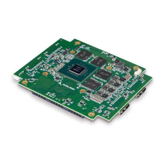
- Page 1 CM5-P1000 NVIDIA Pascal™ GP107 Quadro® P1000 PCIe/104 Graphics Module User’s Manual Manual Rev.: Revision Date: November 1, 2021 Part No: 50M-00052-1000...
- Page 2 Revision History Revision Release Date Description of Change(s) 2021-11-01 intitial release Revision History...
-
Page 3: Preface
CM5-P1000 Preface Copyright © 2021 ADLINK Technology Inc. This document contains proprietary information protected by copy- right. All rights are reserved. No part of this manual may be repro- duced by any mechanical, electronic, or other means in any form without prior written permission of the manufacturer. - Page 4 California Proposition 65 Warning WARNING: This product can expose you to chemicals including acrylamide, arsenic, benzene, cadmium, Tris(1,3-dichloro-2-propyl) phosphate (TDCPP), 1,4- Dioxane, formaldehyde, lead, DEHP, styrene, DINP, BBP, PVC, and vinyl materials, which are known to the State of California to cause cancer, and acrylamide, benzene, cadmium, lead, mercury, phthalates, toluene, DEHP, DIDP, DnHP, DBP, BBP, PVC, and vinyl materials, which are known to the State of California to cause birth defects or other reproductive harm.
-
Page 5: Table Of Contents
CM5-P1000 Table of Contents Revision History..............ii Preface ..................iii List of Tables................. vii List of Figures ................ ix 1 Introduction ................ 1 Overview................1 Features................1 Specifications............... 2 Display Support and Options ..........3 Software Support ..............3 Functional Block Diagram............ 4 Mechanical Dimensions............ - Page 6 Important Safety Instructions..........9 Getting Service ..............13 Table of Contents...
-
Page 7: List Of Tables
CM5-P1000 List of Tables Table 1-1: CM5-P1000 Specifications ......... 2 Table 3-1: Thermal Policy............7 List of Tables... - Page 8 This page intentionally left blank. viii List of Tables...
-
Page 9: List Of Figures
CM5-P1000 List of Figures Figure 1-1: CM5-P1000 Functional Block Diagram ...... 4 Figure 1-2: CM5-P1000 Dimensions..........5 Figure 1-3: CM5-P1000 Mounting Specifications ......6 Figure 1-4: CM5-P1000 PCB Specifications......... 7 Figure 2-1: CM5-P1000 Top Side Layout ........1 Figure 2-2: CM5-P1000 Bottom Side Layout ........ - Page 10 This page intentionally left blank. List of Figures...
-
Page 11: Introduction
CM5-P1000 Introduction 1.1 Overview The CM5-P1000 PCIe104 module is a compact, thin graphics module solution based on the PCI/104-Express™ & PCIe/104™ version 3.0 specification, delivering the latest, leading-edge GPU benefits for your embedded system. Its superior graphics perfor- mance, GPU computing and video capabilities are the ideal solu- tion for performance demanding systems such as digital signage, medical image, defense and aerospace application. -
Page 12: Specifications
Contact +/- 4kV, air +/- 8kV CE, FCC Class B, EN55032, EN55035 Operating System Supported OS Windows 10 & Linux Drivers, 64-bit Miscellaneous Power Consumption Max. 50W 250,000 hrs commercial 40˚C ambient (according to MTBF MIL calculation) Table 1-1: CM5-P1000 Specifications Introduction... -
Page 13: Display Support And Options
CM5-P1000 1.4 Display Support and Options DisplayPort Version 1.4 Max. pixel clock: 1050 MP/s Max. bandwidth: 25.9 GB/s/connector Resolution Up to 5120 x 3200 at 60Hz, with 10-bit color depth Support for High Dynamic Range (HDR) video 1.5 Software Support CUDA Toolkit 8.0... -
Page 14: Functional Block Diagram
IFPA DP1.4 DP Conn 1 IFPB DP1.4 DP Conn 2 Fan Conn IFPE DP1.4 DP Conn 3 IFPF DP1.4 DP Conn 4 SMBus Power Management (PWR_EN PWR_GOOD WAKE#) SPI - VBIOS JTAG Figure 1-1: CM5-P1000 Functional Block Diagram Introduction... -
Page 15: Mechanical Dimensions
CM5-P1000 1.7 Mechanical Dimensions All dimensions shown in mm [thou]. NOTE: NOTE: 115.57 90.17 1.57 95.885 79.375 Figure 1-2: CM5-P1000 Dimensions Introduction... -
Page 16: Figure 1-3: Cm5-P1000 Mounting Specifications
90.805 3575 85.725 3375 82.55 3250 69.004 2716.7 23.004 905.7 3.175 125 5.08 200 Figure 1-3: CM5-P1000 Mounting Specifications Introduction... -
Page 17: Figure 1-4: Cm5-P1000 Pcb Specifications
CM5-P1000 4.191 165 6.35 250 6.35 250 6 236.2 7 275.6 3.2 126 3.175 125 3.175 125 3.2 126 Screw Hole A Screw Hole B Screw Hole C Figure 1-4: CM5-P1000 PCB Specifications Introduction... -
Page 18: Ordering Information
Retain the shipping carton and packing materials for inspection. Obtain authorization from your dealer before returning any product to ADLINK. Ensure that the fol- lowing items are included in the package. CM5-P1000 PCIe/104 Graphics Module Introduction... -
Page 19: Optional Cooling Solutions
The following cooling solutions are available for purchase sepa- rately. Please contact your ADLINK representative for detailed more information and mechanical drawings. CMx-P1000TM-00 CM5-P1000 heat spreader, -40°C to 85°C (P/N: 91-95291-100E) CMx-P1000TM-10 CM5-P1000 passive heat sink, -40°C to 85°C with air flow (P/N: 91-95291-200E) Introduction... - Page 20 CMx-P1000TM-20 CM5-P1000 active heat sink, -10°C to 70°C (P/N: 91-95291-300E) CMx-P1000TM-30 CM5-P1000 active heat sink (for ETT testing only, requires external 4-pin Molex power), -40°C to 85°C (P/N: 91-95291-400E) Introduction...
-
Page 21: Interfaces
CM5-P1000 Interfaces 2.1 Board Layout LED2 LED1 Fan Connector Figure 2-1: CM5-P1000 Top Side Layout LED1 Power on LED LED2 Over-temperature LED Interfaces... -
Page 22: Figure 2-2: Cm5-P1000 Bottom Side Layout
DP 3 DP 2 DP 1 DP 4 External PCIe/104 DC Input Connector Figure 2-2: CM5-P1000 Bottom Side Layout Interfaces... -
Page 23: Connectors
CM5-P1000 2.2 Connectors Fan Connector (1.25mm pitch wafer) Signal FAN_ON FAN_TACH External DC Input (2.00mm pitch wafer) Signal 12V* 12V* Use the same power source as "+12V" of the PCIe104 connec- NOTE: NOTE: Interfaces... - Page 24 DisplayPort Connectors Signal IFPA_L0_C_P IFPA_L0_C_N IFPA_L1_C_P IFPA_L1_C_N IFPA_L2_C_P IFPA_L2_C_N IFPA_L3_C_P IFPA_L3_C_N IFPA_AUX_SEL DP_A_CFG2 IFPA_AUX_C_P IFPA_AUX_C_N IFPA_HPD P_+3V3 CHA_GND CHA_GND CHA_GND CHA_GND Interfaces...
-
Page 25: System Requirements
Figure 3-1: Power Sequencing 3.2 Module Power Up and Down Issuing the PWR_EN signal powers the CM5-P1000 module down, and the system designer can decide whether to keep the module input power when the CM5-P1000 module is powered down. System Requirements... -
Page 26: Reset Requirements
MODULE INPUT POWER PWR_EN MODULE INTERNAL POWER PWR_GOOD Figure 3-2: Module Power Down 3.3 Reset Requirements PVPERL PERST-PG FAIL PERST-CLK MODULE INPUT POWER PVPERL PERST-CLK PWR_EN PERST-PG FAIL PWR_GOOD PEX_REFCLK PEX_RST# Figure 3-3: Reset Sequencing System Requirements... -
Page 27: Thermal Policy
CM5-P1000 3.4 Thermal Policy The GPU core clock throttles at temperatures (T ) past the thresh- olds shown with the behaviors as listed. Thermal throttling ensures that the highest temperature on the die does not exceed the sense temperature for prolonged periods of time. -
Page 28: Bios Settings
3.5 BIOS Settings When the CM5-P1000 is used with the ADLINK CM4-SL2 PCI/104-Express SBC, please use the following BIOS settings to ensure proper graphics functionality. 1. Advanced > Graphics > Primary Display: set to PCIE 2. Boot > CSM > Video: set to UEFI 3. - Page 29 CM5-P1000 Important Safety Instructions For user safety, please read and follow all instructions, Warnings, Cautions, and Notes marked in this manual and on the associated device before handling/operating the device, to avoid injury or damage. S'il vous plaît prêter attention stricte à tous les avertissements et mises en garde figurant sur l'appareil , pour éviter des blessures...
- Page 30 Never attempt to repair the device, which should only be serviced by qualified technical personnel using suitable tools A Lithium-type battery may be provided for uninterrupted backup or emergency power. Risk of explosion if battery is replaced with one of an incorrect type;...
- Page 31 CM5-P1000 BURN HAZARD Touching this surface could result in bodily injury. To reduce risk, allow the surface to cool before touching. RISQUE DE BRÛLURES Ne touchez pas cette surface, cela pourrait entraîner des blessures. Pour éviter tout danger, laissez la surface refroidir avant de la toucher.
- Page 32 This page intentionally left blank. Important Safety Instructions...
- Page 33 San Jose, CA 95119-1208, USA Tel: +1-408-360-0200 Toll Free: +1-800-966-5200 (USA only) Fax: +1-408-600-1189 Email: info@adlinktech.com ADLINK Technology (China) Co., Ltd. 300 Fang Chun Rd., Zhangjiang Hi-Tech Park Pudong New Area, Shanghai, 201203 China Tel: +86-21-5132-8988 Fax: +86-21-5132-3588 Email: market@adlinktech.com...
Need help?
Do you have a question about the CM5-P1000 and is the answer not in the manual?
Questions and answers