Mandik MSD Manual
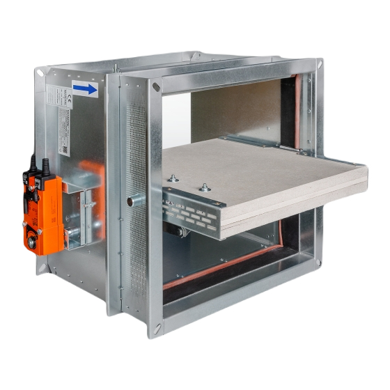
Multi smoke damper
Hide thumbs
Also See for MSD:
- Manual (63 pages) ,
- Technical documentation manual (49 pages) ,
- Manual (56 pages)
Table of Contents
Advertisement
Quick Links
Advertisement
Table of Contents

Related Manuals for Mandik MSD


Summary of Contents for Mandik MSD
-
Page 2: Table Of Contents
These technical specifications state a row of manufactured sizes and models of multi smoke dampers (further only dampers) MSD. It is valid for production, designing, ordering, delivery, maintenance and operation. 1. Description......................... 2. Design..........................3. Dimensions, weights......................12 4. Placement and Assembly....................20 5. -
Page 3: Description
• Cycling test in class C acc. to EN 12101-8 • ES Certificate of conformity No. 1391-CPR-2021/0084 • Declaration of Perfomance No. PM/MSD/01/21/3 • Hygienic assessment of fire dampers - Report No. 1.6/pos/19/19c Porous concrete ceiling construction, thickness 150 mm... -
Page 4: Design
Working conditions Exact damper function is provided under the following conditions: a) maximum air velocity 15 m/s b) un derpressure max. -1500 Pa or overpressure max. 500 Pa. Dampers can be installed in arbitrary position (horizontal or vertical blade axis). Dampers are designed for macroclimatic areas with mild climate according to EN 60 721-3-3. - Page 5 AC/DC 24 V AC/DC 24 V AC 230 V Power voltage 50/60Hz 50/60Hz 50/60Hz Power consumption - in operation - in the end position 0,1 W 0,3 W 0,4 W Dimensioning 6 VA (Imax 8,2 A @ 5 ms) 6,5 VA (Imax 8.2 A @ 5 ms) 7 VA (Imax 4 A @ 5 ms) Protection class Degree of protection...
- Page 6 AC/DC 24 V AC/DC 24 V AC 230 V Power voltage 50/60Hz 50/60Hz 50/60Hz Power consumption - in operation 2,5 W 3,5 W - in the end position 0,1 W 0,3 W 0,4 W Dimensioning 5 VA (Imax 8,2 A @ 5 ms) 5,5 VA (Imax 8.2 A @ 5 ms) 6 VA (Imax 4 A @ 5 ms) Protection class...
- Page 7 AC/DC 24 V AC 230 V Power voltage 50/60Hz 50/60Hz Power consumption - in operation 12 W - in the end position 0,5 W 0,5 W Dimensioning 18 VA (Imax 8,2 A @ 5 ms) 15 VA (Imax 7,9 A @ 5 ms) Protection class Degree of protection IP 54...
- Page 8 24-240 VAC/DC Nominal voltage 50/60Hz Power consumption - motoring 10 W - heating 16 W (start at -20°C) Protection class Degree of protection IP 66 Running time for 95° < 60 s Ambient temperature range -40°C … +50°C Non-operating temperature -40°C …...
- Page 9 Design with the communication and supply device BKNE 230-24 Design with communication and power supply device BKNE 230-24 and with actuator BEN (BEE, BE)-ST for 24V. The BKNE 230-24 serves on the one hand as a decentralized network device for powering the actuator and on the other hand transmits the signal of the communication and control device BKSE 24-6.
- Page 10 Communication and supply device Power voltage AC 230V 50/60Hz Power consumption 10 W (including actuator) Dimensioning 19 VA (including actuator) Protection class Ambient operation temperature -30°C … +50°C Storage temperature -40°C … +80°C Connection - network cable 1 m without plug - drive 6-pin plug, 3-pin plug - terminal blocks...
- Page 11 Communication and control devices indicates operating condition and faults of flue dampers. These conditions can be signalled or transmitted to the higher-level control system via the auxiliary built-in contacts. Signals from individual BKNE 230-24 are evaluated separately. All BKNE 230-24 are controlled simultaneously.
-
Page 12: Dimensions, Weights
X = 94mm - BEN 98mm - BEE 115,2mm - BE 151mm - SCHISCHEK Position: 1 MSD - design „A‟ see chapter 18 2 Actuating mechanism 3 Damper blade 4 Access door/ inspection cover X = 168mm - BEN (BEE) - Page 13 Y = 250mm - BEN (BEE) 260mm - BE 260mm - SCHISCHEK Z = 300mm - BEN (BEE) 370mm - BE 430mm - SCHISCHEK Position: 1 MSD - design „IB‟ see chapter 18 2 Insulation box 3 Damper blade 4 Access door/ inspection cover...
- Page 14 Weight and effective area 0,0162 12,2 BELIMO BEN 0,0984 22,4 BELIMO BEN 0,0191 12,6 BELIMO BEN 0,1040 23,1 BELIMO BEN 41,5 0,0228 13,1 BELIMO BEN 0,1077 23,5 BELIMO BEN 0,0264 13,6 BELIMO BEN 0,1169 24,6 BELIMO BEN 0,0307 14,3 BELIMO BEN 0,1188 24,9 BELIMO BEN...
- Page 15 86,5 0,0655 17,8 BELIMO BEN 0,0449 16,3 BELIMO BEN 106,5 0,0761 18,9 BELIMO BEN 41,5 0,0534 BELIMO BEN 0,0880 BELIMO BEN 0,0619 17,7 BELIMO BEN 0,1012 21,3 BELIMO BEN 0,0721 18,6 BELIMO BEN 0,1145 22,6 BELIMO BEN 0,0789 19,2 BELIMO BEN 0,1277 23,8 BELIMO BEN...
- Page 16 0,2749 BELIMO BEN 0,2627 32,7 BELIMO BEN 0,2793 34,3 BELIMO BEN 0,2681 33,1 BELIMO BEN 0,2967 35,6 BELIMO BEN 0,2899 34,5 BELIMO BEN 0,3184 38,2 BELIMO BEE 0,3063 35,6 BELIMO BEN 0,0543 18,4 BELIMO BEN 0,3172 36,3 BELIMO BEN 0,0640 19,1 BELIMO BEN 0,3444...
- Page 17 86,5 0,1568 26,4 BELIMO BEN 0,0970 23,8 BELIMO BEN 106,5 0,1822 BELIMO BEN 41,5 0,1154 BELIMO BEN 0,2108 29,7 BELIMO BEN 0,1338 BELIMO BEN 0,2426 31,7 BELIMO BEN 0,1558 27,3 BELIMO BEN 0,2743 33,6 BELIMO BEN 0,1705 28,1 BELIMO BEN 0,3061 35,6 BELIMO BEN...
- Page 18 0,5593 51,7 BELIMO BE 0,5953 55,9 BELIMO BEE 0,5682 52,2 BELIMO BE 0,6076 56,5 BELIMO BEE 0,6036 54,1 BELIMO BE 0,6570 BELIMO BE 0,6478 56,5 BELIMO BE 0,6941 60,8 BELIMO BE 0,1103 27,4 BELIMO BEN 0,7188 62,1 BELIMO BE 0,1300 28,6 BELIMO BEN 0,7805...
- Page 19 Open damper blade overlaps the damper body by the value “c” or “a” and “c”. These values are specified in the Tab. 3.2.1. Values "c" and "a" has to be respected when projecting related smoke exhaust ducts. For the design .66 (with BKNE supply and communication device) add to weight of the damper with an actuating mechanism (from the Tab.
-
Page 20: Placement And Assembly
Smoke dampers are intended for use in spaces with multiple fire compartments, which can be connected by a smoke extraction duct tested according to EN 1366-8 or EN 1366-9 or can be installed in the construction of the fire compartment. Dampers can be installed with the actuator on the top, bottom* or either side. - Page 21 The control mechanism has to be protected (covered) against damage and pollution during installation process. During installation the damper blade must be in position “CLOSED”. The damper body should not be deformed in the course of installation. Once the damper built in, its blade should not blade should move freely and must not foul the damper casing during operation.
-
Page 22: Statement Of Installations
Fire Compartment Fire Compartment Fire Compartment Fire Compartment Fire Compartment Fire Compartment Fire Compartment Fire Compartment Fire Compartment Fire Compartment Fire Compartment Fire Compartment Position: Wall British gypsum thistle bond 60 min. density 670 kg/m³ Ablative Coated Batt (e.g. Firestop Board HILTI CFS-CT B 1S 140/50 - min. - Page 23 Mortar or gypsum EIS 120 Ablative Coated Batt EIS 90 Insulation with ROCKWOOL FIREPRO - mortar or gypsum EIS 120 Insulation with ROCKWOOL FIREPRO - Ablative Coated Batt EIS 90 Mortar or gypsum EIS 120 Ablative Coated Batt EIS 90 EI 120, min.
- Page 24 ≥ 50 Position: MSD - design „A‟ see chapter 18 Solid wall construction separating FIRST fire compartment from following compartment British gypsum thistle bond 60 (or equivalent can by used) minimum density 670 kg/m³) ≥...
- Page 25 ≥ 100 Position: MSD - design „IB‟ see chapter 18 Solid wall construction separating FIRST fire compartment from following compartment British gypsum thistle bond 60 (or equivalent can by used) minimum density 670 kg/m³) Fixing profile with threaded rod see. chapter 6 ROCKWOOL FIREPRO DuctRock Slab th.
- Page 26 ≥ 100 Position: MSD - design „IB1‟ see chapter 18 Solid wall construction separating FIRST fire compartment from following compartment Ablative Coated Batt (e.g. Firestop Board HILTI CFS-CT B 1S 140/50 - min. density 140 kg/m + Firestop acrylic sealant HILTI CFS-S ACR or equivalent) Fire stop coating thickness 1 mm (e.g.
- Page 27 ≥ 50 Position: MSD - design „A‟ see chapter 18 Gypsum wall construction separating FIRST fire compartment from following compartment British gypsum thistle bond 60 (or equivalent can by used) minimum density 670 kg/m³) Fixing profile with threaded rod see.
- Page 28 * meets EI 120, but min. th. 125 mm Position: MSD - design „IB‟ see chapter 18 Gypsum wall construction separating FIRST fire compartment from following compartment British gypsum thistle bond 60 (or equivalent can by used) minimum density 670 kg/m³) Fixing profile with threaded rod see.
- Page 29 * meets EI 120, but min. th. 125 mm Position: MSD - design „IB1‟ see chapter 18 Gypsum wall construction separating FIRST fire compartment from following compartment Ablative Coated Batt (e.g. Firestop Board HILTI CFS-CT B 1S 140/50 - min. density 140...
- Page 30 ≥ 50 * min. 110 mm - Concrete/ min. 125 mm - Aerated concrete Position: MSD - design „A‟ see chapter 18 Solid ceiling construction separating FIRST fire compartment from following compartment British gypsum thistle bond 60 (or equivalent can by used) minimum density 670 kg/m³)
- Page 31 Connection detail on page 39-40 Position: MSD - design „IB‟ see chapter 18 Solid ceiling construction separating two fire compartments British gypsum thistle bond 60 (or equivalent can by used) minimum density 670 kg/m³) Stone wool bound with use of an organic resin with Connection detail crushed stone as a refrigerant, min.
-
Page 32: Suspension Systems
43 Connection detail on page 43 Position: MSD - design „IB1‟ Fixing profile with threaded rod see. chapter 6.4. SUPALUX / PROMATECT-L500 - th. min 40 mm Protection box of actuator - part of the IB, IB1 damper design Note: There is no protection box in designs A and A1. - Page 33 The dampers and duct must be suspended separately. Position: MSD - design „IB1‟ Fixing profile with threaded rod see. chapter 6.4. Protection box of actuator - part of the IB, IB1 damper design Note: There is no protection box in designs A and A1.
- Page 34 The dampers must be suspended using threaded rods and mounting profiles. Their dimensioning depends on the damper's weight. The dampers and duct must be suspended separately. The connected duct must be suspended in such a way that the transfer of all loads from the adjoining ventilation duct to the damper body is completely excluded.
- Page 35 max. 50 Position: Threaded rod M8 - M20 Support HILTI MQ-41 (or MQ-41/3 or equivalent) Bored plate HILTI MQZ-L or equivalent Washer for M8 - M20 Nut M8 - M20...
-
Page 36: Duct Connection
Position: Connecting air duct MULTI Flange of MSD Flange of duct M8 bolt assembly - MSD damper are equipped with rivet nuts on the flanges* Ceramic self-adhesive tape (FJ 120 Pyrosil B 170-250 kg/m - Tremco-illbruck) or equivalent Lock washers... - Page 37 - design „A‟ Position: ROCKWOOL FIREPRO DuctRock Slab th. 90 mm acc. to EN 1366-8 Part of MSD - design „A‟ Wall British gypsum thistle bond 60 (or equivalent can by used) minimum density 670 kg/m³)
- Page 38 - design „A1‟ Position: ROCKWOOL FIREPRO DuctRock Slab th. 90 mm acc. to EN 1366-8 Part of MSD - design „A1‟ Wall Ablative Coated Batt (e.g. Firestop Board HILTI CFS-CT B 1S 140/50 - min. density 140 kg/m Firestop acrylic sealant HILTI CFS-S ACR or equivalent)
- Page 39 - design „IB‟ Position: ROCKWOOL FIREPRO DuctRock Slab th. 90 mm acc. to EN 1366-8 Part of MSD - design „IB‟ Wall British gypsum thistle bond 60 (or equivalent can by used) minimum density 670 kg/m³)
- Page 40 - design „IB‟ Position: ROCKWOOL FIREPRO DuctRock Slab th. 90 mm acc. to EN 1366-8 Part of MSD - design „IB‟ Wall British gypsum thistle bond 60 (or equivalent can by used) minimum density 670 kg/m³)
- Page 41 - design „IB1‟ Position: ROCKWOOL FIREPRO DuctRock Slab th. 90 mm acc. to EN 1366-8 Part of MSD - design „IB1‟ Wall Ablative Coated Batt (e.g. Firestop Board HILTI CFS-CT B 1S 140/50 - min. density 140 kg/m Firestop acrylic sealant HILTI CFS-S ACR or equivalent)
- Page 42 - design „IB1‟ Position: ROCKWOOL FIREPRO DuctRock Slab th. 90 mm acc. to EN 1366-8 Part of MSD - design „IB1‟ Wall Ablative Coated Batt (e.g. Firestop Board HILTI CFS-CT B 1S 140/50 - min. density 140 kg/m Firestop acrylic sealant HILTI CFS-S ACR or equivalent)
- Page 43 - design „IB1‟ Position: ROCKWOOL FIREPRO DuctRock Slab th. 90 mm acc. to EN 1366-8 Part of MSD - design „IB1‟...
-
Page 44: Pressure Loss
Pressure loss calculation [Pa] pressure loss [m.s ] air flow speed in nominal damper section [kg.m ] air density coefficient of local pressure loss for the nominal damper section (see Tab. 9.1.1.) Determination of pressure loss by using diagram = 1,2 kg.m... -
Page 45: Coefficient Of Local Pressure Loss
Coefficient of local pressure loss 2,1314 1,6906 1,3782 1,1149 1,0037 0,9288 0,7918 0,6827 0,6003 0,5350 1,9945 1,5804 1,2423 1,0368 0,9748 0,8785 0,7383 0,6367 0,5585 0,4976 1,9207 1,5162 1,1256 0,9994 0,9341 0,8442 0,7137 0,6078 0,5329 0,4772 1,8415 1,4584 1,1032 0,9651 0,9009 0,8068 0,6837 0,5832... -
Page 46: Noise Data
Level of acoustic output corrected with filter A. + 10 log(S) + K [dB(A)] level of acoustic output corrected with filter A [dB] level of acoustic output L related to the 1 m section (see Tab. 10.3.1.) [m ] duct cross section [dB] correction to the weight filter A (see Tab. - Page 47 -4,5 -6,9 -10,9 -16,7 -24,1 -33,2 -43,9 -56,4 -3,9 -5,3 -8,4 -13,1 -19,5 -27,6 -37,4 -48,9 -3,9 -4,5 -6,9 -10,9 -16,7 -24,1 -33,2 -43,9 -4,0 -4,1 -5,9 -9,4 -14,6 -21,5 -30,0 -40,3 -4,2 -3,9 -5,3 -8,4 -13,1 -19,5 -27,6 -37,4 -4,5 -3,9 -4,9...
-
Page 48: Material
Damper bodies are supplied in the standard design made of galvanized plate without any other surface finish. Damper blades are made of fire resistant asbestos free boards made of calcium-silicate. Fasteners is galvanized. According to the customer's requirements, damper can be made of stainless material. Specifications for stainless-steel models –... -
Page 49: Logistic Terms
Dampers are delivered on a pallets. As standard, the dampers are wrapped in plastic foil for protection during transport and must not be used for long-term storage of the equipment . Changes in temperature during transport may cause condensation of water vapour inside the packaging and thereby condisitions may arise inside the packaging that are suitable for corrosion of materials used in the equipment (e.g. -
Page 50: Assembly
Assembly, maintenance and damper function check can be done only by qualified and trained person, i.e. “AUTHORIZED PERSON” according to the manufacturer documentation. All works done on the fire dampers must be done according international and local norms and laws. All effective safety standards and directives must be observed during fire damper assembly. -
Page 51: Entry Into Service And Revisions
Spare parts are supplied only on basis of an order. Data label is placed on the damper body. MANDÍK, a.s. Dobříšská 550, 267 24 Hostomice, Czech Republic DIMENSION: ACTUATING SYSTEM: WEIGHT (kg): YEAR/SER.NO.: MANUAL FIRE PROTEC. CLASS: TPM 109/15 EN 12101-8:2011 Cert. No.: 1391-CPR-2021/0084, DoP: PM/MSD/01/21/3 1391... -
Page 52: Ordering Key
Smoke damper MSD technical specifications design does not include protection box of the actuator and does not include protective cladding boards in line with the blade design does not include protection box of the actuator and includes protective cladding boards in line with the blade... - Page 53 MANDÍK, a.s. Dobříšská 550 26724 Hostomice Czech Republic Tel.: +420 311 706 706 E-Mail: mandik@mandik.cz www.mandik.cz The producer reserves the right for innovations of the product. For actual product information see www.mandik.com...
Need help?
Do you have a question about the MSD and is the answer not in the manual?
Questions and answers