Table of Contents
Advertisement
Quick Links
Advertisement
Table of Contents

Subscribe to Our Youtube Channel
Related Manuals for Mandik SEDS-R


Summary of Contents for Mandik SEDS-R
-
Page 2: Table Of Contents
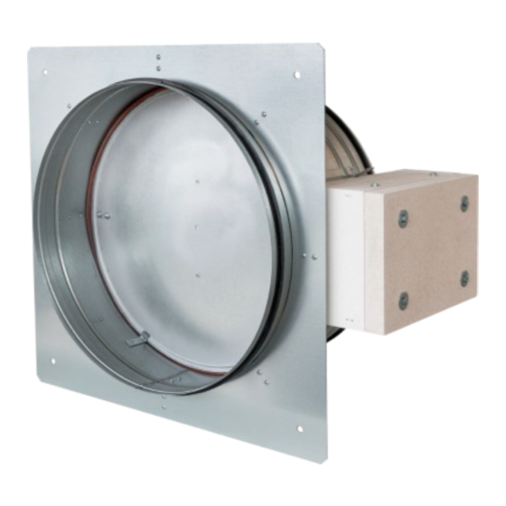
These technical specifications state a row of manufactured sizes and models of round smoke extraction dampers - single (further only dampers) SEDS-R. It is valid for production, designing, ordering, delivery, maintenance and operation. 1. Description......................... 2. Design..........................3. Dimensions, weights...................... -
Page 3: Description
• External Casing leakage min. class B, Over blade min. class 4, diameter 100 min. class 3 • Cycling test in class C acc. to EN 12101-8 • ES Certificate No. 1391-CPR-2020/0188 • Declaration of Perfomance No. PM/SEDS-R/01/20/2 • Hygienic assessment of fire dampers - Report No. 1.6/pos/19/19c... -
Page 4: Design
Working conditions Dampers are designed for smoke exhaust piping systems with underpressure max. 1500 Pa or overpressure max. 500 Pa. Dampers are designed for maximum air velocity 15 m/s. Dampers are designed for installation with horizontal blade axis. Flow direction has to be led from actuating side (it is labeled by arrow on the damper casing). - Page 5 AC/DC 24 V AC/DC 24 V AC 230 V Power voltage 50/60Hz 50/60Hz 50/60Hz Power consumption - in operation - in the end position 0,1 W 0,3 W 0,4 W Dimensioning 6 VA (Imax 8,2 A @ 5 ms) 6,5 VA (Imax 8.2 A @ 5 ms) 7 VA (Imax 4 A @ 5 ms) Protection class Degree of protection...
- Page 6 Design with the communication and power supply unit Design with communication and power supply device BKNE 230-24 and with actuator BEN 24-ST. The BKNE 230-24 serves on the one hand as a decentralized network device for powering the actuator and on the other hand transmits the signal of the communication and control device BKSE 24-6.
- Page 7 Communication and supply device Power voltage AC 230V 50/60Hz Power consumption 10 W (including actuator) Dimensioning 19 VA (including actuator) Protection class Ambient operation temperature -30°C … +50°C Storage temperature -40°C … +80°C Connection - network cable 1 m without plug - drive 6-pin plug, 3-pin plug - terminal blocks...
- Page 8 Communication and control devices indicates operating condition and faults of flue dampers. These conditions can be signalled or transmitted to the higher-level control system via the auxiliary built-in contacts. Signals from individual BKNE 230-24 are evaluated separately. All BKNE 230-24 are controlled simultaneously.
-
Page 9: Dimensions, Weights
Dimensions Position: Damper body Damper blade Actuating mechanism cover Installation flange Weights and effective area 0,0061 BELIMO BEN (15 N.m) 10,5 0,0100 BELIMO BEN (15 N.m) 0,0172 BELIMO BEN (15 N.m) 11,5 0,0222 BELIMO BEN (15 N.m) 0,0278 BELIMO BEN (15 N.m) 0,0446 BELIMO BEN (15 N.m) 13,5... -
Page 10: Placement And Assembly
For damper (Fig. 10) the open damper blade overlaps the damper body from dimension D=315 by the value “a” or “a” and “c”. These values are specified in the Tab. 3.2.1. Values "a" and "c" has to be respected when projecting related smoke exhaust ducts. Smoke extraction dampers single are designed to remove heat and combustion products (e.g. - Page 11 Installation examples Position: Damper hinge Holder L Threaded rod Washer Screw connection Profile 30x30...
-
Page 12: Suspension Systems
Mounting to the ceiling wall Position: ² Threaded rod M8 – M20 36,6 Washer 84,3 Coupling Nut Anchor Hinge plate - min. thickness 10 mm Concrete screw tested for fire resistance R30-R90, max. Tension up to 0.75 KN (length 35 mm) -
Page 13: Pressure Loss
Pressure loss calculation [Pa] presure loss [m.s ] air flow speed in nominal damper section [kg.m ] air density coefficient of local pressure loss for the nominal damper section (see Tab. 7.1.1.) Determination of pressure loss by using diagram = 1,2 kg.m Coefficient of local pressure loss (-) 1,111 0,930... -
Page 14: Noise Data And Pressure Loses
842 1122 1403 1683 1964 2244 2525 2806 1069 1425 1782 2138 2494 2851 3207 3563 1357 1810 2262 2714 3167 3619 4072 4524 1716 2289 2861 3434 4006 4578 5150 5722 905 1018 1131 2121 2827 3534 4241 4948 5655 6362 7069 884 1060 1237 1414 1590 1767 2659 3545 4431 5317 6203 7090 7976 8862 886 1108 1329 1551 1773 1994 2216... -
Page 15: Material
Damper casing and damper blade are made of galvanized plate without any other surface finish. Fasteners are galvanized. The appliance is constructed and preset by the manufacturer, its operation is dependent on proper installation and adjustment. Dampers are transported by box freight vehicles without direct weather impact, there must not occur any shocks and ambient temperature must not exceed +40°C. - Page 16 Drill two holes into the protection box (from outside to inside) and pull through field wiring cables (fire resistant cables) to connect actuator trailing lead. Protection box is made of calcium silicate plates. Use drill (drill size acc. To suit connecting cable Ø + 2 mm for seal up by mastic) and make two holes (see fig.
-
Page 17: Entry Into Service And Revisions
Before entering the dampers into operation after assembly and after sequential revisions, checks and functionality tests of all designs including operation of the electrical components must be successfully provided and finished. After entering into operation, these revisions must be done according to requirement set by national regulations. -
Page 18: Product Label
DIMENSION: ACTUATING SYSTEM: WEIGHT (kg): YEAR/SER.NO.: MANUAL FIRE PROTEC. CLASS: TPM 120/16 EN 12101-8:2011 Cert. No.: 1391-CPR-2020/0188, DoP: PM/SEDS-R/01/20/2 1391 technical specifications design according tab. 16.1.1. size type with actuating mechanism BEN for 230V with actuating mechanism BEN for 24V... - Page 19 MANDÍK, a.s. Dobříšská 550 26724 Hostomice Czech Republic Tel.: +420 311 706 706 E-Mail: mandik@mandik.cz www.mandik.com The producer reserves the right for innovations of the product. For actual product information see www.mandik.com...
Need help?
Do you have a question about the SEDS-R and is the answer not in the manual?
Questions and answers