Table of Contents
Advertisement
Quick Links
Advertisement
Table of Contents

Related Manuals for Mandik MSD Square


Summary of Contents for Mandik MSD Square
-
Page 2: Table Of Contents
TPM 109/15 These technical specifications state a row of manufactured sizes and models of multi smoke dampers (further only dampers) MSD. It is valid for production, designing, ordering, delivery, maintenance and operation. I. CONTENT II. GENERAL INFORMATION 1. Description......................... 2. Design..........................3. -
Page 3: General Information
TPM 109/15 II. GENERAL INFORMATION 1. Description Fig. 1 Damper MSD - square Fig. 2 Damper MSD - round Multi smoke dampers are shutters in the smoke exhaust duct systems. The dampers are 1.1. designed to remove heat and combustible products (e.g. smoke) from effected fire compartments. In the event of fire the Smoke and Fire ventilation system opens the damper in the affected section and removes combustion products and heat from this section. -
Page 4: Design
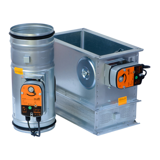
TPM 109/15 Working conditions 1.3. Exact damper function is provided under the following conditions: a) maximum air velocity 15 m.s b) underpressure max. -1500 Pa or overpressure max. 500 Pa. Dampers can be installed in arbitrary position (horizontal or vertical blade axis). Dampers are designed for macroclimatic areas with mild climate according to EN 60 721-3-3. - Page 5 TPM 109/15 Fig. 4 Actuating mechanism BELIMO BLE 24(-ST) AC 24 V Connection through an insulation transformer. DC 24 V BLE24-ST: Design with connector plugs for communication to network and communication device BKNE230-24 BLE24 (-ST) <3° <87° Parrallel connection of other driver is possible. Pay attention to the power input data.
- Page 6 TPM 109/15 Fig. 6 Actuating mechanism BELIMO BE 24-12(-ST) AC 24 V Connection through an insulation transformer. DC 24 V BE24-12-ST: Design with connector plugs for communication to network and communication device BKNE230-24 BE24-12 (-ST) <3° <87° Parrallel connection of other driver is possible. Pay attention to the power input data.
- Page 7 TPM 109/15 Fig. 8 Actuating mechanism SCHISCHEK InMax 50.75-S 24...230 VAC/DC Integrated aux. switches max 24V/3A, 240V/0,25A switching at 5° and 85°. <5° >85° 1 2 3 4 5 6 heater Design with the communication and supply device 2.2. Design .66 Design with the communication and supply device BKNE230-24 and the actuating mechanism BLE24(BE24-12)-ST.
- Page 8 TPM 109/15 Tab. 2.2.1. Communication and supply device BKNE 230-24 Communication and supply device BKNE 230-24 Nominal voltage AC 230V 50/60Hz Power consumption 10 W (including actuating mechanism) Dimensioning 19 VA (including actuating mechanism) Degree of protection Ambient temperature range - 30 °C …...
- Page 9 TPM 109/15 Fig. 11 Electric actuating mechanism with emergency function and electromagnet Electromagnet (solenoid) Electromagnet (solenoid) Pulse switch Pulse switch Actuating mechanism Actuating mechanism Tab. 2.3.1. Actuting mechanism BELIMO BLF 24, BLF 230 Actuting mechanism BELIMO BLF 24 BLF230 AC 230 V 50/60Hz Nominal voltage AC 24V 50/60Hz DC 24 V...
- Page 10 TPM 109/15 Obr. 13 Actuting mechanism BLF 230 N L1 For separation from the mains, a device that AC230 V insulates polar conductors must be at disposal (Minimum distance between contacts - 3 mm). BLF230 <5° <80° Parrallel connection of other driver is possible. Pay attention to the power input data.
-
Page 11: Communication And Control Devices
TPM 109/15 Tab. 2.1.2. Elektromagnet EM230 Obr. 15 Elektromagnet EM230 Elektromagnet EM230 Jmenovité napětí AC 230 V / 50 Hz Zátahový proud 1,2 A Krytí IP 40 Teplota okolí provozní -10 °C … +40 °C Připojení kabel 1m, 3x0,75mm 3. Communication and control devises BKSE24-6 indicates operating status and fault signals for the smoke extraction dampers. -
Page 12: Dimensions, Weights
TPM 109/15 Fig. 16 Communication and control devices BKSE 24-6 Input 1 BKSE24-6 Input 2 (isolated) SMOKE EXTRACTION AUTO CEASE SMOKE EXTRACTION AC 24 V Connection through a1...a6 an insulation transformer. Delay 0 s (Fan) Delay 60 s (Fan) a1...a6 OPEN CLOSED *Fault (Error) - Page 13 TPM 109/15 Fig. 18 Square MSD - design with electric actuating mechanism with emergency function and electromagnet Position: Damper body Actuating mechanism Damper blade Electromagnet (solenoid) Inspection hole covering Pulse switch SIEM24 Fig. 19 Round MSD (MD-W) - design with actuating mechanism Position: Damper body Inspection hole covering...
- Page 14 TPM 109/15 Fig. 20 Round MSD (MSD-W) - design with electric actuating mechanism with emergency function and electromagnet Position: Damper body Actuating mechanism Damper blade Electromagnet (solenoid) Inspection hole covering Pulse switch SIEM24 Weight and effective area 4.2. Tab. 4.2.1. Weight and effective area - square dampers MSD-W Efective Overlaps...
- Page 15 TPM 109/15 MSD-W Efective Overlaps MSD-W Size with electromagnet area [m ] weight actuator weight actuator weight actuator 0,0185 11,6 12,1 12,6 BELIMO BLE BELIMO BLF BELIMO BLE 180 x 180 0,0218 12,0 12,5 13,0 BELIMO BLE BELIMO BLF BELIMO BLE 180 x 200 0,0259 12,5...
- Page 16 TPM 109/15 MSD-W Efective Overlaps MSD-W Size with electromagnet area [m ] weight actuator weight actuator weight actuator 0,0907 19,9 20,4 20,9 BELIMO BLE BELIMO BLF BELIMO BLE 225 x 500 0,1012 21,1 21,6 22,1 BELIMO BLE BELIMO BLF BELIMO BLE 225 x 550 0,1033 21,3...
- Page 17 TPM 109/15 MSD-W Efective Overlaps MSD-W Size with electromagnet area [m ] weight actuator weight actuator weight actuator 0,0319 13,7 14,2 14,7 BELIMO BLE BELIMO BLF BELIMO BLE 300 x 180 0,0376 14,3 14,8 15,3 BELIMO BLE BELIMO BLF BELIMO BLE 300 x 200 0,0447 14,9...
- Page 18 TPM 109/15 MSD-W Efective Overlaps MSD-W Size with electromagnet area [m ] weight actuator weight actuator weight actuator 0,1469 23,8 26,1 24,8 BELIMO BLE JOVENTA DAFx.20S BELIMO BLE 355 x 500 0,1639 25,2 27,5 26,2 BELIMO BLE JOVENTA DAFx.20S BELIMO BLE 355 x 550 0,1673 25,5...
- Page 19 TPM 109/15 MSD-W Efective Overlaps MSD-W Size with electromagnet area [m ] weight actuator weight actuator weight actuator 0,0543 17,4 17,9 18,4 BELIMO BLE BELIMO BLF BELIMO BLE 500 x 180 0,0640 18,1 18,6 19,1 BELIMO BLE BELIMO BLF BELIMO BLE 500 x 200 0,0761 18,9...
- Page 20 TPM 109/15 MSD-W Efective Overlaps MSD-W Size with electromagnet area [m ] weight actuator weight actuator weight actuator 0,2354 29,9 32,3 30,9 BELIMO BLE JOVENTA DAFx.20S BELIMO BLE 560 x 500 0,2627 31,7 34,0 32,7 BELIMO BLE JOVENTA DAFx.20S BELIMO BLE 560 x 550 0,2681 32,1...
- Page 21 TPM 109/15 MSD-W Efective Overlaps MSD-W Size with electromagnet area [m ] weight actuator weight actuator weight actuator 0,0711 20,1 20,6 21,1 BELIMO BLE BELIMO BLF BELIMO BLE 650 x 180 0,0838 20,9 21,4 21,9 BELIMO BLE BELIMO BLF BELIMO BLE 650 x 200 0,0997 22,0...
- Page 22 TPM 109/15 MSD-W Efective Overlaps MSD-W Size with electromagnet area [m ] weight actuator weight actuator weight actuator 0,3002 34,4 36,7 35,4 BELIMO BLE JOVENTA DAFx.20S BELIMO BLE 710 x 500 0,3350 36,5 38,8 37,5 BELIMO BLE JOVENTA DAFx.20S BELIMO BLE 710 x 550 0,3419 36,9...
- Page 23 TPM 109/15 MSD-W Efective Overlaps MSD-W Size with electromagnet area [m ] weight actuator weight actuator weight actuator 0,0991 24,6 25,1 25,6 BELIMO BLE BELIMO BLF BELIMO BLE 900 x 180 0,1168 25,7 26,2 26,7 BELIMO BLE BELIMO BLF BELIMO BLE 900 x 200 0,1389 27,0...
- Page 24 TPM 109/15 MSD-W Efective Overlaps MSD-W Size with electromagnet area [m ] weight actuator weight actuator weight actuator 0,4687 46,4 48,7 48,4 BELIMO BLE JOVENTA DAFx.20S BELIMO BE 1100 x 500 0,5230 50,2 51,5 51,2 BELIMO BE JOVENTA DAFx.20S BELIMO BE 1100 x 550 0,5338 50,7...
- Page 25 TPM 109/15 MSD-W Overlaps MSD-W Efective with electromagnet Size area [m ] weight actuator weight actuator weight actuator 0,1663 35,5 36,0 36,5 BELIMO BLE BELIMO BLF BELIMO BLE 1500 x 180 0,1960 37,1 37,6 38,1 BELIMO BLE BELIMO BLF BELIMO BLE 1500 x 200 0,2331 39,0...
- Page 26 TPM 109/15 For square damper (Fig. 21) the open damper blade overlaps the damper body by the value “c” 4.3. or “a” and “c”. These values are specified in the Tab. 4.2.1. For round damper (Fig. 22) the open damper blade overlaps the damper body by the value “f” These values are specified in the Tab.
-
Page 27: Placement And Assembly
TPM 109/15 5. Placement and Assembly Multi smoke extraction dampers are designed to remove heat and combustion products (e.g. 5.1. smoke) from fire compartments according EN1366-8. Multi smoke extraction dampers are designed to horizontal or vertical installation with arbitrary blade axis position. To provide needed access space to the control device, all other objects must be situated at least 350 mm from the control parts of the damper. - Page 28 TPM 109/15 The control mechanism has to be protected (covered) against damage and pollution during 5.3. installation process. During installation the damper blade must be in position “CLOSED”. The damper body should not be deformed in the course of installation. Once the damper built in, its blade should not grind on the damper casing during opening or closing.
- Page 29 TPM 109/15 Installation examples 5.5. Tab. 5.5.1. Statement of installations Filling of space between Placement Figure damper and wall mortar or gypsum In solid wall construction mortar or gypsum Square In solid ceiling construction mortar or gypsum In gypsum wall construction mortar or gypsum In solid wall construction mortar or gypsum...
- Page 30 TPM 109/15 Fig. 30 Installation in a solid wall construction - MSD-R (MSD-W-R) ≥ 50 POSITION: Damper MSD (MSD-W) ≥ 100 Mortar or gypsum with min. density 800 kg/m Fig. 31 Installation in a solid ceiling construction - MSD-S (MSD-W-S) ≥...
- Page 31 TPM 109/15 Fig. 32 Installation in a solid ceiling construction - MSD-R (MSD-W-R) ≥ 50 ≥ 150 POSITION: Damper MSD (MSD-W) Mortar or gypsum with min. density 800 kg/m Duct suitable for multi compartment (insulated) Fig. 33 Installation in a gypsum wall construction - MSD-S (MSD-W-S) ≥...
-
Page 32: Technical Data
TPM 109/15 Fig. 34 Installation in a gypsum wall construction - MSD-R (MSD-W-R) ≥ 50 POSITION: Damper MSD (MSD-W) Mortar or gypsum with min. density 800 kg/m ≥ 100 III. TECHNICAL DATA 6. Pressure loss Pressure loss calculation 6.1. [Pa] pressure loss [m.s ] air flow speed in nominal damper section... -
Page 33: Coefficient Of Local Pressure Loss
TPM 109/15 Determination of pressure loss by using diagram = 1,2 kg.m 6.2. Diagram 6.2.1. Pressure losses for air density =1,2 kg.m 7. Coefficient of local pressure loss Tab. 7.1.1a. Coefficient of local pressure loss (-) - square dampers 2,1314 1,6906 1,3782 1,1149... -
Page 34: Noise Data
TPM 109/15 Tab. 7.1.1b. Coefficient of local pressure loss (-) - square dampers 0,4879 0,4665 0,4462 0,4216 0,4109 0,3916 0,3884 0,3820 0,3681 0,3585 0,4526 0,4323 0,4152 0,3959 0,3820 0,3681 0,3606 0,3552 0,3424 0,3328 0,4355 0,4152 0,4002 0,3788 0,3681 0,3531 0,3456 0,3413 0,3338 0,3221... - Page 35 TPM 109/15 Level of acoustic output in octave ranges. 8.2. + 10 log(S) + L Woct [dB] spectrum of acoustic output in octave range Woct [dB] level of acoustic output L related to the 1 m section (see Tab. 10.3.1. a 10.3.2) [m ] duct cross section [dB]...
-
Page 36: Material, Finishing
TPM 109/15 Tab. 8.3.3. Correction to the weight filter A - square and round dampers w [m.s ] -15,0 -11,8 -9,8 -8,4 (7,30 Kč) -6,4 -5,7 -5,0 -4,5 -4,0 -3,6 [dB] Tab. 8.3.4. Relative level expressing the shape of the spectrum L - square and round dampers f [Hz] w [m.s ]... -
Page 37: Transportation And Storage
TPM 109/15 VI. TRANSPORTATION AND STORAGE 11. Logistic terms Dampers are transported by box freight vehicles without direct weather impact, there must not 11.1. occur any sharp shocks and ambient temperature must not exceed + 40 °C. Dampers must be protected against mechanic damages when transported and manipulated. -
Page 38: Spare Parts
TPM 109/15 Before entering the dampers into operation after their assembly and by sequential checks, the 13.2. following checks must be carried out for all designs. Visual inspection of proper damper integration, inside damper area, damper blade, contact surfaces and silicon sealing. Inspection hole disassembly: release the covering lid by turning the wing nut and while turning the lid right or left release it from the security belt. -
Page 39: Ordering Key
TPM 109/15 IX. ORDERING INFORMATION 16. Ordering key Smoke damper MSD 16.1. TPM 109/15 MSD-S 800x400 - technical specifications design size - square (rectangular) - round type Dampers design Additional digit with actuating mechanism BLE230(BE230-12), InMax 50.75-S with actuating mechanism BLE24(BE24-12), InMax 50.75-S with the communication and supply device BKNE 230-24 and actuating mechanism... - Page 40 MANDÍK, a.s. Dobříšská 550 26724 Hostomice Czech Republic Tel.: +420 311 706 706 Fax: +420 311 584 810, 311 584 38 E-Mail: mandik@mandik.cz www.mandik.cz The producer reserves the right for innovations of the product. For actual product information see www.mandik.com...
Need help?
Do you have a question about the MSD Square and is the answer not in the manual?
Questions and answers