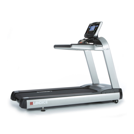
Landice L-10 Service Manual
Hide thumbs
Also See for L-10:
- Owner's manual (36 pages) ,
- Installation manual (28 pages) ,
- Owner's manual (54 pages)
Table of Contents
Advertisement
Quick Links
Advertisement
Chapters
Table of Contents

Related Manuals for Landice L-10


Summary of Contents for Landice L-10
- Page 1 L-10 Treadmill Service Manual Endurance and 9” Display Consoles...
-
Page 2: Table Of Contents
Table of Contents Landice Service Warranty Policy ................................4 Service Claim Form ..................................... 5 Operation and Safety Instructions: ................................6 Electrical Requirements ....................................8 Multimeter Instructions ....................................9 Measuring AC & DC Amperage:................................10 Maintenance Checklist ....................................11 Static Electricity: What to Look For ................................12 Treadmill Specifications: ................................... - Page 3 Endurance Diagnostic Flow Chart ................................63...
-
Page 4: Landice Service Warranty Policy
Landice will reimburse the selling dealer or service provider according to our labor rate schedule. If you are a service provider for Landice and do not sell our product, you have the option of billing us directly or you can bill back the selling dealer. -
Page 5: Service Claim Form
Service Claim Form... -
Page 6: Operation And Safety Instructions
Use the treadmill only for its intended use as described in this manual. Do not use attachments not recommended by Landice. Never operate treadmill if it has a damaged cord or plug, if it is not working properly, or if it has been damaged. - Page 7 Operation and Safety Instructions: Failure to observe the following warning statements can result in serious injury! •Do not use this product without first consulting your doctor if you suffer from any illness, condition, or disability that affects your ability to run, walk or exercise. •Do not use this product without supervision present if you are suffering from any illness, condition, or disability which affects your ability to run, walk or exercise.
-
Page 8: Electrical Requirements
Electrical Requirements Landice requires that a dedicated circuit be wired for each piece of Landice equipment. For optimal performance, DO NOT plug equipment into an AFCI or GFI circuit breaker/outlet. Adapters or extension cords should not be used. Treadmills marked 120 VAC are intended for use with a grounding plug in a nominal 120-volt circuit. -
Page 9: Multimeter Instructions
Multimeter Instructions Using Your Multimeter A Multimeter is a device used to measure a variety of electrical functions. The multimeter best suited to diagnosing a treadmill will be able to measure AC and DC voltage, as well as Ohms and electrical continuity. Make sure the batteries in your Multimeter are fresh before you begin! -
Page 10: Measuring Ac & Dc Amperage
Measuring AC & DC Amperage: Amperage must be performed on the BROWN WIRE of the line cord. DC Amperage must be performed on the BLACK WIRE from the drive motor. AMP METER CLAMP Aac Indicates AC Amperage Adc Indicates DC Amperage PERFORMING AMPERAGE INSTRUCTIONS Start by clamping your meter to the wire. -
Page 11: Maintenance Checklist
•Clean treadbelt walking surface: Vacuum treadbelt to remove loose dirt. If vacuuming does not remove dirt, Landice recommends the use of a medium stiff nylon bristle brush to remove dirt trapped in treadbelt surface. A damp (not wet!) sponge can be used to finish the cleaning process. -
Page 12: Static Electricity: What To Look For
Do monthly maintenance such as vacuuming under the motor cover. Use Simple Green to wipe down the deck, hand rails and display. Check the treadbelt tension, and look for cracks or fraying. A Landice Authorized service provider can help to do a full diagnostic on your treadmill for a fee. -
Page 13: Treadmill Specifications
Treadmill Specifications: L10-Club Treadmill Specifications Model Display Digital Display Launch Date Apr-2017 Mechanical Features Drive Motor 5HP AC Drive Voltage Speed Range 0.5 - 15.5mph Incline 0-15% Treadbelt 22" x 60" Frame Material Steel Deck 1" Reversible Roller 3 1/2" Cross Bar Controls Side Rails Heart Rate... -
Page 14: Electrical Schematic
Electrical Schematic:... -
Page 15: Upper Consoles
Upper Consoles: ENDURANCE DISPLAY PST-7/CT-7 – 9” DISPLAY... -
Page 16: Motor Pan Components
Motor Pan Components: LOWER BOARD (INVERTER) AC DRIVE MOTOR LINE FILTER ELEVATION MOTOR CHOKE Lower Board (Inverter- Wiring) 1) From Lower Board (Inverter) to Display 2) From Lower Board (Inverter) to Elevation Motor 3) From Filter to Lower Board (Inverter) Black and Red, wires power the Inverter. 4) From Lower Board (Inverter) to Drive Motor 2) Elevation Harness 4) Drive Motor Harness... -
Page 17: Remote Control Console
Motor Pan Components: Brown wire from switch to choke to filter. Black Wire from switch to filter. LINE FILTER Black wire and Red wire to the Lower Board (Inverter). Remote Control Console: Remote Console Pin/Wire harness designations on L10 Treadmill. Pins 2-7 are for Reading Switched, Pins 1, 8, and 12 are Power Pins, Pin 9 is Safety Key, and Pins 10 and 11 are the two Heart Rate Inputs. -
Page 18: Incline
Remote Control Console: INCLINE SWITCH MEMBRANE STOP/START SWITCHES SPEED SWITCH EMERGENCY STOP SAFETY LANYARD Upper Display Board Ribbon Cable Contact Heart Rate Wireless Heart Rate Membrane Ribbon Cable SPEED INCLINE CONTROL CONTROL SWITCH SWITCH HOUSING FOR SAFETY LANYARD AND EMERGENCY STOP... -
Page 19: Error Code & Diagnostics - Endurance Console
Error Code & Diagnostics – Endurance Console: Note: A logs of recent error codes are found in the Engineering Mode 1.) ER01 – Communication Error Communication disruption between the inverter and the upper control board: The inverter sends a signal to the upper control board every 1.5 seconds to check to see if they are still in communication with each other. - Page 20 Error Code & Diagnostics – Endurance Console: 5) ER05 – AC Motor Voltage Error AC Motor voltage monitoring The inverter can monitor the motor voltage and determine if it’s receiving too much or too little voltage The potential reasons for an AC motor low or high voltage: ...
-
Page 21: Troubleshooting & Diagnostics
Troubleshooting & Diagnostics: OTHER TROUBLESHOOTING: Display will not turn on when Start is pressed 1) Check for correct power voltage at the power outlet. 2) Check for power at the end of the power cord. 3) Check the On/Off switch to be “ON” position and switch lit. 4) Check to see if the Circuit breaker tripped. -
Page 22: Display Options - Endurance Console
Display Options – Endurance Console: TURN OFF BEEP SOUND: The beeper is set to ON by default. When a button is pressed on the display or the mini-pod a beep will sound. To turn off the beeper: Press the Start button, and when the mill starts to boot up, press Incline “Down”... -
Page 23: Engineering Mode - Endurance Console
Engineering Mode – Endurance Console: FOLLOW THE STEPS BELOW TO ENTER ENGINEERING MODE : 1) Start machine and then pull the safety key out 2) Press Speed Keys + (plus) and – (minus) simultaneously and count 3 seconds. 3) Push the safety key back and then release the + and – keys. PO1 should appear on the screen. -
Page 24: Display Options And Diagnostics- 9" Display Series Console
Display Options and Diagnostics- 9” Display Series Console: TO ENTER ENGINEERING/DIAGNOSTIC MODE: Press and hold 3, 9 Start until the following screen comes up: Use the +/- keys to scroll through menu, START button to enter into mode. The STOP button will go back to the menu. Error Logs –... - Page 25 CT-7/PST-7 Software Update Instructions Landice 9” Display Series Treadmill Step 1 With the treadmill turned off, press the “3”, “9” and “START” key simultaneously. The Hidden Menu screen will appear. Using the “ ” key, scroll down to Reprogram Firmware and press the “START”...
-
Page 26: Membrane/Display Panel
Membrane/Display Panel Removal & Installation Instructions: INTRODUCTION: This document is for the installation and removal of the Upper Display Board for the L10 Treadmill. TOOLS REQUIRED: Phillips Head Screwdriver BEFORE YOU BEGIN: Make sure that the treadmill is switched off at the power switch, and the line cord is unplugged from the outlet before you begin to replace the upper display board. - Page 27 Membrane Panel/Display Removal & Installation Instructions: Display Board Connections Ports: Step 3 CSAFE Port Fan Relay Upper Harness Heart Rate Mini Pod Membrane Panel Connector Carefully disconnect each cable from the upper board, taking note of where they were connected. The illustration above will help you connect the correct cable to its corresponding port.
-
Page 28: Remote Console Removal & Installations Instructions
Remote Console Removal & Installations Instructions: INTRODUCTION: This document is to be used for removal/installation of the Remote Console (#75020) TOOLS REQUIRED: Phillips Head Screwdriver BEFORE YOU BEGIN: Disconnect the power source before removing the remote console. Step 1 Lift and remove the accessory tray cover located between the display and remote console to access the remote console wiring, as shown in Illustration A. -
Page 29: Speed
Remote Control Console Removal & Installations Instructions: Step 3 Proceed to remove the remote console trim plate, allowing access to circuit board connections (Illustration E). Carefully disconnect the contact heart rate and wireless heart rate (optional with Club PT and PST) from the circuit board, as circled in Illustration F. TO INSTALL, REVERSE THE FOLLOWING STEPS ABOVE! Upper Display Board Ribbon Cable Contact Heart Rate... -
Page 30: Motor Cover Removal
Motor Cover Removal & Installation: INTRODUCTION: This document is for installation and removal of the motor cover (#10045). TOOLS REQUIRED: 4mm Allen Wrench Using a Allen Wrench, loosen and remove three Allen head bolts, one in the motor cover, and two holding the upright base cover in place, as shown in Illustration A and B. -
Page 31: Side Frame Cover
Side Frame Cover (Traction Strip) Removal & Installation: INTRODUCTION: This document is to be used for installation and removal of the Side Frame Covers (Traction Strips - #10046) 4mm Allen Wrench TOOLS REQUIRED: 1/2” Wrench BEFORE YOU BEGIN: You will need to remove the motor cover, upright base cover, and the bed end caps before you can remove the side frame covers. - Page 32 Side Frame Cover & Traction Strip Removal & Installation: Step 5 With the three bolts loosened as shown in the illustration, you can now remove the side frame cover. When installing the new side frame cover, be sure to line up the side frame cover with the mounting holes on the frame.
-
Page 33: Drive Roller
Drive Roller Removal & Installation: INTRODUCTION: This document is to be used for the installation and removal of the Front (Drive) Roller (#10028). 5mm Allen Wrench ½” Socket Wrench TOOLS REQUIRED: Socket Wrench BEFORE YOU BEGIN You will need to remove the motor cover, upright end cover caps, and side frame cover to gain access to the drive roller. - Page 34 Drive Roller Removal & Installation: Step 3 Next, remove the drive roller from the right side insert, as shown in Illustration C. You can now remove the front roller from the machine, as shown in Illustration Step 4 Remember to first place the drive belt around the drive roller and drive motor shaft, as seen in Illustration E.
-
Page 35: Rear Roller
Rear Roller Removal & Installation: INTRODUCTION: This document is for the installation and removal of the Rear (Take-Up) Roller (#10029). 4mm Allen Wrench TOOLS REQUIRED: 5mm Allen Wrench BEFORE YOU BEGIN You will need to remove the bed end caps before you can remove the rear roller. - Page 36 Rear Roller Removal & Installation: Step 3 Remove the rear roller from the treadmill. When installing, be sure to line up the rear roller axle with the frame inserts shown above. The treadbelt needs to be tensioned after rear roller installation.
-
Page 37: Treadbelt
Treadbelt Removal & Installation: INTRODUCTION: This document is for installation and removal of the Treadbelt (#10023) and flipping the Deck(#10024). 4mm Allen Wrench, TOOLS REQUIRED: 5mm Allen Wrench BEFORE YOU BEGIN: You will need to remove the motor cover, upright base cover, bed end caps, side frame covers, front, and rear rollers before you can remove the treadbelt. -
Page 38: Treadbelt Tracking & Tensioning
Treadbelt Tracking & Tensioning Treadbelt Tracking & Tensioning Instructions: Tracking Instructions: Left Left Right Right If the Treadbelt is tracking to the right (Figure A): Tighten the right bolt (clockwise), or loosen the left bolt (counter-clockwise) using your 5mm Allen Wrench. ... -
Page 39: Deck
Deck Removal & Installation: INTRODUCTION: This document is for removal and installation of the Deck (#10024). 4mm Allen Wrench TOOLS REQUIRED: ½ Wrench BEFORE YOU BEGIN: You will need to remove the motor cover, upright base cover, bed end caps, and side frame covers before you can remove the deck. - Page 40 Deck Removal & Installation: Deck Installation/Removal Instructions Step 2 FLIP DECK With the deck bolts removed, simply slide the deck out from underneath the treadbelt and flip or replace with a new deck if it has been already flipped previously. (Please note that the deck can be flipped when replacing the treadbelt) Once the new treadbelt is replaced and the deck has been flipped, then place the assembled belt and deck on the treadmill, and reverse the instructions to finish installation.
-
Page 41: Impact Absorbers
Impact Absorbers Removal & Installation: Absorber Installation/Removal Instructions INTRODUCTION: This document is for installation and removal of the absorbers. 13mm Wrench & Socket 4mm Allen Wrench TOOLS REQUIRED: BEFORE YOU BEGIN: You will need to remove the motor cover, upright base cover, bed end caps, side frame covers, treadbelt and the deck before you can remove the absorbers. - Page 42 Absorber Installation/Removal Instructions Step 2 Using your 13mm wrench, loosen and remove the serrated nut attached to the bottom of the absorber. It may be helpful to use the socket attachment for some of the absorbers. Remove the washer from the blue absorbers. Step 3 Once you have removed all the absorbers, simply reverse the steps shown here to install.
-
Page 43: Drive Motor
Drive Motor Drive Motor Installation/Removal Instructions INTRODUCTION: This document is for installation and removal of the AC Drive Motor (#10037). 13mm Socket Tools Required: Socket Wrench 4” Socket Wrench Extender BEFORE YOU BEGIN: This is a high voltage AC unit. Please turn off and remove power from the treadmill before removing or installing parts. - Page 44 AC Drive Motor Removal & Installation: Drive Motor Installation/Removal Instructions Step 3 Locate the 4 brass threaded inserts in the motor pan. Install the drive motor in the motor pan, aligning the motor bracket with the 4 brass threaded inserts. Step 4 Assemble all (4) bolts with the flat metal washer and rubber grommet as shown in the illustration above.
-
Page 45: Drive Belt
Drive Belt Installation & Removal Drive Belt Installation/Removal Instructions INTRODUCTION: This document is for the installation and removal of the drive belt (#10030) 5mm Allen Wrench TOOLS REQUIRED: ½” Socket & Socket Wrench BEFORE YOU BEGIN: You will need to remove the motor cover, upright end cover caps, and side frame cover (Left Side Only) to gain access to the drive belt. -
Page 46: Elevation Motor
Elevation Motor Removal & Installation: Elevation Motor Installation/Removal Instructions This document is for installation and removal of the Elevation Motor (#10064). INTRODUCTION: WARNING: THIS IS A HIGH AC VOLTAGE SO BE SURE TO UNPLUG THE TREADMILL 13mm Socket Wrench TOOLS REQUIRED: ... -
Page 47: Start
Elevation Motor Removal & Installation: Step 3 Underneath the motor pan, use the 5/8” wrench to remove the nut and bolt connecting the elevation shaft to the leg assembly, as shown in Illustration E. Remove the elevation motor, as shown in Illustration Step 4 To Install, reverse the steps shown here to finish installation. -
Page 48: Inverter Board
Inverter Board (Lower Board) Removal & Installation: Inverter Board (Lower Board) Installation/Removal Instructions INTRODUCTION: This document is to be used for installation/removal of the Inverter board(#10011). Phillips Head Screwdriver TOOLS REQUIRED: Cordless Screw Gun w/ Phillips Head Tip BEFORE YOU BEGIN: Power off the unit and unplug from power source before removal. - Page 49 Inverter Board (Lower Board) Wiring Schematic: Step 3 Filter Choke Drive Motor Elevation Motor Lower Harness With the screws removed, and all harnesses disconnected, proceed to remove the lower board from the motor pan. To install, simply reverse the steps shown here.
-
Page 50: Landice Vision System
Landice Vision System Installation Instructions: LVS Installation Instructions INTRODUCTION: This is to be used for installation of the Landice LVS Vision System. 4mm Allen Wrench Phillips Head Screwdriver TOOLS REQUIRED: ¼ Metal Drill Bit & Cordless Drill Wire Guide ... - Page 51 LVS Installation Instructions: LVS Installation Instructions Step 2 Using a Phillips Screw Driver loosen and remove all (3) Phillips Head Screws, then the reading rack, and finally remove the display assembly from the control console as shown in Illustration A. Using a Allen Wrench, loosen and remove all 4 (M6x75) button head cap screws holding the control console to the upright.
- Page 52 LVS Installation Instructions: BVE Remote Control Installation Instructions Step 4 ¼” From Side of Console ½” From Top of Louver Using the BVE Mounting Bracket, measure and mark the holes for the mounting bracket in its place on the back of the console as shown in Illustration A.
- Page 53 L10 Button Feedback L10 Button Feedback Display Buttons Button Code INCLINE + INCLINE - SPEED + SPEED - STOP START EXPRESS 1 EXPRESS 2 Keypad # 1-0 11-20 Remote Console INCLINE + INCLINE - SPEED + SPEED - STOP/SAFETY STOP RESUME...
-
Page 54: Contact Heart Rate Diagnostics
Contact Heart Rate Diagnostics: Contact Heart Rate Diagnostics Step 1 Place your hands on both pulse grips and keep them there for 5-10 seconds. The heart rate icon should blink, and provide BPM information. If it doesn’t appear, you will need to remove the outer cover of the Remote Console (see Remote Console Instructions) and proceed to Step 2. - Page 55 Contact Heart Rate Diagnostics: Heart Rate Diagnosis ACCUTRACK CHR Crossbar Diagnosis: 1. There should be a constant 4.8-5.0Vdc across the red & brown wires on ACCUTRACK CHR Crossbar harness. If there is 0Vdc then the remote console is bad. If the ACCUTRACK CHR Crossbar is working properly this is what you should see with your voltmeter (Not touching the grips).
-
Page 56: Pulse Heart Rate Diagnostics
Pulse Heart Rate Diagnostics: Heart Rate Receiver / Chest Strap Diagnosis: There should be a constant 4.5Vdc – 5Vdc across the brown & black wires on the heart rate receiver harness. If you measure 0Vdc across those two points, then the remote control console is bad. If the heart rate receiver is working properly, this is what you should see on your voltmeter. -
Page 57: Heart Rate Diagnostics Flow Chart
Heart Rate Diagnostics Flow Chart:... -
Page 58: No Power To Upper Console - Endurance
No Power to Upper Console - Endurance... -
Page 59: Safety Key Error - Endurance Console
Safety Key Error - Endurance Console... -
Page 60: No Power To The Upper Console - 9" Series
No Power to the Upper Console - 9” Series... -
Page 61: Po Error - 9" Series
PO Error - 9” Series... -
Page 62: Safety Key Error - 9" Series
Safety Key Error - 9” Series... - Page 63 Endurance Diagnostic Flow Chart: ERROR CODE DESCRIPTION DIAGNOSIS SOLUTION ER01 Loss of communication from Check Upper Harness for 1). Replace Upper Harness Communication the upper board to the loose wires or connection. 2). Replace Display Board. Failure inverter board. 3). Replace Inverter Board. No elevation during use.
- Page 64 L10 Bed - Exploded View...
- Page 65 L10 - Motors & Rollers Exploded View...
- Page 66 L10 UPRIGHT EXPLODED VIEW Part Description View # Part Number L10 Upright Assembly 10051 Remote Console & 73030 CHR Assembly Display Assembly, L10 10032 Handrail, Left, L10 73018 Handrail, Right, L10 73017 Bridge Assembly – 73031 Bottle Holder, L10 L10 Base Assembly 10010 M5x15 Socket Head M5x15_SHCS...
Need help?
Do you have a question about the L-10 and is the answer not in the manual?
Questions and answers