
Related Manuals for MKS Newport XPS-RLD


Summary of Contents for MKS Newport XPS-RLD
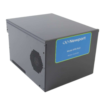
- Page 1 XPS-RLD Universal High-Performance Motion Controller/Driver Start-Up Manual A1279A...
-
Page 2: Warranty
XPS-RLD Controller Start-Up Manual Warranty Newport Corporation warrants that this product will be free from defects in material and workmanship and will comply with Newport’s published specifications at the time of sale for a period of one year from date of shipment. If found to be defective during the warranty period, the product will either be repaired or replaced at Newport's option. -
Page 3: Table Of Contents
XPS-RLD Controller Start-Up Manual Table of Contents Waranty ........................ii EU Declaration of Conformity ................... Preface ........................viii Introduction ..................... 1 Scope of the Manual ....................1 Definitions and Symbols ..................... 1 1.2.1 General Warning or Caution ..............1 1.2.2 Electric Shock .................... 2 1.2.3 European Union CE Mark ................ - Page 4 XPS-RLD Controller Start-Up Manual Connecting to the XPS ....................16 3.5.1 Direct Connection to the XPS Controller ..........17 3.5.2 Connecting the XPS to a Corporate Network Using Static IP Configuration ................... 20 3.5.3 Configuring the XPS for Connection to a Corporate Network Using Dynamic IP Configuration ...............
- Page 5 XPS-RLD Controller Start-Up Manual Appendix D: PCO Connector ............... 41 Description ........................ 41 Appendix E: Motor Driver Cards ............43 Universal digital DC, Stepper and Direct Drive Motor Driver XPS-DRV11 ... 43 Piezoelectric Motor Driver XPS-DRVP1 ..............44 DC and Stepper Motor Driver XPS-DRV01 ............. 45 Three phase AC Brushless Driver XPS-DRV02 ............
-
Page 6: Eu Declaration Of Conformity
XPS-RLD Controller Start-Up Manual EU Declaration of Conformity A1279A0 - EDH0420En1010 – 12/19... - Page 7 XPS-RLD Controller Start-Up Manual A1279A0 - EDH0420En1010 – 12/19...
-
Page 8: Preface
XPS-RLD Controller Start-Up Manual Preface Confidentiality & Proprietary Rights Reservation of Title The Newport Programs and all materials furnished or produced in connection with them ("Related Materials") contain trade secrets of Newport and are for use only in the manner expressly permitted. Newport claims and reserves all rights and benefits afforded under law in the Programs provided by Newport Corporation. -
Page 9: Service Information
XPS-RLD Controller Start-Up Manual Service Information The user should not attempt any maintenance or service of the XPS Series Controller/Driver system beyond the procedures outlined in this manual. Any problem that cannot be resolved should be referred to Newport Corporation. When calling Newport regarding a problem, please provide the Tech Support representative with the following information: •... -
Page 11: Introduction
XPS-RLD Controller Start-Up Manual Universal High-Performance Motion Controller/Driver XPS-RLD Controller Introduction Scope of the Manual The XPS-RLD is an extremely high-performance, easy to use, integrated motion controller/driver offering high-speed communication through 10/100/1000 Base-T Ethernet, outstanding trajectory accuracy and powerful programming functionality. It combines user-friendly web interfaces with advanced trajectory and synchronization features to precisely control from the most basic to the most complex motion sequences. -
Page 12: Electric Shock
XPS-RLD Controller Start-Up Manual 1.2.2 Electric Shock Figure 2: Electrical shock symbol. The Electrical Shock Symbol in Figure 2 may appear on labels affixed to the XPS Series Controller/Driver. This symbol indicates a hazard arising from dangerous voltages. Any mishandling could result in damage to the equipment, personal injury, or even death. -
Page 13: Warning, Caution And Note Definition
XPS-RLD Controller Start-Up Manual Warning, Caution and Note Definition The following are definitions of the Warnings, Cautions and Notes that may be used in this manual to call attention to important information regarding personal safety, safety and preservation of the equipment, or important tips. WARNING Situation has the potential to cause bodily harm or death. - Page 14 XPS-RLD Controller Start-Up Manual • Do not open the XPS Controller/Driver stand-alone motion controller. There are no user-serviceable parts inside the XPS Controller/Driver. • Return equipment to Newport Corporation for service and repair. • Dangerous voltages associated with the power supply are present inside Controller/Driver unit.
-
Page 15: System Overview
XPS-RLD Controller Start-Up Manual System Overview Specifications • 1 to 4 axes of stepper, DC brush, DC brushless, linear or piezo motors using internal drives: XPS-RLDM: 1-axis; XPS-RLD2: 2-axis; XPS-RLD4: 4-axis. Number of Axes • Other motion devices using external third-party drives •... - Page 16 XPS-RLD Controller Start-Up Manual • Open loop, PI position, PIDFF velocity, PIDFF acceleration, PIDDualFF voltage • Variable PID’s (PID values depending on distance to target position) Control Loop • Deadband threshold; Integration limit and integration time • Derivative cut-off filter; 2 user-defined notch filters •...
-
Page 17: Drive Options
XPS-RLD Controller Start-Up Manual Drive Options The XPS-RLD controller is capable of driving up to 4 axes of most Newport positioners using driver cards that slide through the back of the chassis. These factory-tested drives are powered by an internal power supply, which is independent of the controller power supply. -
Page 18: Front Panel Description
XPS-RLD Controller Start-Up Manual Front Panel Description Figure 7: Front panel of XPS-RLD Controller/Driver. TheXPS-RLD front panel is free of any connection or command device. A1279A0 - EDH0420En1010 – 12/19... -
Page 19: Rear Panel Description
XPS-RLD Controller Start-Up Manual Rear Panel Description Figure 8: Rear panel of XPS-RLD Controller/Driver. NOTE The Main Power ON/OFF Switch is located next to the inlet for the power cord. The switch and the inlet must be accessible to the user. 2.5.1 Axis Connectors (AXIS 1 –... -
Page 20: Ethernet Configuration
XPS-RLD Controller Start-Up Manual Ethernet Configuration Figure 10: Ethernet configuration. 2.6.1 Communication Protocols The Ethernet connection provides a local area network through which information is transferred in units known as packets. Communication protocols are necessary to dictate how these packets are sent and received. The XPS Controller/Driver supports the industry standard protocol TCP/IP. -
Page 21: Programming With Tcl
XPS-RLD Controller Start-Up Manual different PC than the first task yet be simultaneously executed within the XPS. Alternatively, if the auto-focusing system is providing an analog feedback, this task could have been implemented as a TCL script within the XPS (see the next topic). Second, the concept of sockets has another practical advantage for many laboratory users since the use of threads allows them to share the same controller for different applications at the same time. -
Page 22: Getting Started
XPS-RLD Controller Start-Up Manual Getting Started Unpacking and Handling It is recommended that the XPS Controller/Driver be unpacked in your lab or work site rather than at the receiving dock. Unpack the system carefully; small parts and cables are included with the equipment. Inspect the box carefully for loose parts before disposing of the packaging. -
Page 23: Rack Mounting Kit
XPS-RLD Controller Start-Up Manual CAUTION No cables should be connected to the controller at this point! 3.4.1 Rack Mounting Kit The XPS-RLD controller is basically intended to be installed on a flat surface such as a table or a cabinet shelf. A rack mounting kit can be provided separately to properly secure the controller in a standard 19"... -
Page 24: Installing Driver Cards
XPS-RLD Controller Start-Up Manual Figure 12: Rear rack mounting. 3.4.2 Installing Driver Cards Figure 13: Installing driver cards. No driver is included except for XPS-RLDM, already fitted with an XPS-DRV02 card. Due to the high power of the XPS-RLD controller, ventilation is very important. To ensure a good level of heat dissipation, the following rules must be followed: 1. -
Page 25: Connecting To The Main
XPS-RLD Controller Start-Up Manual 4. The surrounding ventilation holes at the sides and back of the XPS unit must be free from obstructions that prevent the free flow of air. If necessary, proceed as follows: • Refer to Driver boards specifications in appendix for appropriate driver card choice. •... -
Page 26: Power On
XPS-RLD Controller Start-Up Manual 3.4.4 Power ON • Turn the Main Power Switch to ON (located on the Rear Panel). • There is an initial beep after power on and a second beep when the controller has finished booting. If the controller boots properly, the second beep is happy- sounding, otherwise the sad-sounding beep is emitted. -
Page 27: Direct Connection To The Xps Controller
XPS-RLD Controller Start-Up Manual 3.5.1 Direct Connection to the XPS Controller For a direct connection between a PC and the XPS controller you need to use the Ethernet cable and either the REMOTE or the HOST connector at the back of the XPS. Figure 16: Direct connection to the XPS using an Ethernet cable. - Page 28 XPS-RLD Controller Start-Up Manual This procedure is for the Windows 7 operating system (almost similar process for Windows 8): • Start Button > Control Panel > Network and Sharing Center => Change adapter settings. • Right Click on Local Area Connection Icon and select Properties. •...
- Page 29 XPS-RLD Controller Start-Up Manual Procedure for connecting to the controller: • Open an Internet Browser and connect to http://192.168.0.254 in case using HOST connector or connect to http://192.168.254.254 in case using REMOTE connector. Login: Name: Administrator Password: Administrator (Please see the picture below). Role: Administrator NOTE Please note that the login text is case sensitive.
-
Page 30: Connecting The Xps To A Corporate Network Using Static Ip Configuration
XPS-RLD Controller Start-Up Manual 3.5.2 Connecting the XPS to a Corporate Network Using Static IP Configuration Once you are logged in using the previously described steps with a direct connection, you can change the IP configuration of the controller in order to connect the XPS over a Network. -
Page 31: Configuring The Xps For Connection To A Corporate Network Using Dynamic Ip Configuration
XPS-RLD Controller Start-Up Manual • Click "OK" and reboot the controller by clicking REBOOT. A pop-up windows appears showing the “REBOOT IN PROGRESS”. When the boot sequence is complete, the user is redirected to the login page. The time to reboot is about 50 seconds. - Page 32 XPS-RLD Controller Start-Up Manual • Go to the TERMINAL window, click on the Reboot function, then press the OK button: • Wait for controller to reboot, open the internet browser and connect again to REMOTE You can see the dynamic IP address in Controller → General. The IP address delivered by your DHCP is displayed above.
-
Page 33: Recovering A Lost Ip Configuration
XPS-RLD Controller Start-Up Manual • Make sure that the Ethernet cable is connected to the HOST connector of the XPS controller and to your network. • Open your internet browser and use the dynamic IP address. • Check with your IT department that the lease time set at the DHCP is longer than the time you plan to leave the XPS switched off otherwise you will lose your dynamic address and will need to connect to the REMOTE to know the new assigned one by the DHCP. -
Page 34: Testing Your Xps-Pc Connection And Communication
XPS-RLD Controller Start-Up Manual First, the IP address on the PC’s Ethernet card must be set to Obtain IP Address Automatically. • Open Internet Browser and connect to http://192.168.254.254 Login: Name: Administrator Password: Administrator (Please see the picture below). Rights: Administrator NOTE Please note that the login text is case sensitive. - Page 35 XPS-RLD Controller Start-Up Manual If the XPS is connected and communicates properly, it replies in the terminal window that appears after clicking on the OK button: If the XPS controller is not communicating, the window displays that the time delay of the request is exceeded.
-
Page 36: Connecting The Stages
XPS-RLD Controller Start-Up Manual Connecting the Stages CAUTION Never connect/disconnect stages while the XPS controller is powered CAUTION Mount the stage(s) on a flat, stable surface before connecting to the XPS controller. • Power off the controller. • Carefully connect the supplied cables to the stage and to the appropriate axis connector at the rear of the controller. -
Page 37: Documentation
XPS-RLD Controller Start-Up Manual Documentation Under the webpage Documentation, users can open and download XPS manuals and drivers. 3.10 SFTP (Secured File Transfer Protocol) Connection All usual file management can be done from the controller website interface. Nevertheless, SFTP connection is another option to manage file transfers from an external application. - Page 38 XPS-RLD Controller Start-Up Manual The folders of the XPS controller are displayed (see below). Browse through the different folders and transfer data from or to your host PC. When connected to the controller with FTP as Administrator, the user has access to configuration files.
-
Page 39: Samba Microsoft Smb/Cifs Networking Protocol
XPS-RLD Controller Start-Up Manual 3.11 Samba Microsoft SMB/CIFS Networking Protocol A secured protocol (Samba) has been implemented and also allows the controller Public folder (this folder only) to be attached and detached to the computer as a network drive. 3.12 System Shut-Down To shut down the system entirely, perform the following procedure: •... -
Page 40: Maintenance And Service
XPS-RLD Controller Start-Up Manual Maintenance and Service Enclosure Cleaning The XPS-RLD Controller/Driver should only be cleaned with a sufficient amount of soapy water solution. Do not use an acetone or alcohol solution; this will damage the finish of the enclosure. Obtaining Service The XPS-RLD Controller/Driver contains no user serviceable parts. -
Page 41: Appendix A: Hardware
XPS-RLD Controller Start-Up Manual Appendix Appendix A: Hardware Controller Weight: 5.5 kg (12.1 lb) with 4 driver boards Air flow: 45 CFM A1279A0 - EDH0420En1010 – 12/19... -
Page 42: Controller With Rack Mounting Kit
XPS-RLD Controller Start-Up Manual Controller with Rack Mounting Kit 5.3.1 Front Rack Mounting 5.3.2 Rear Rack Mounting A1279A0 - EDH0420En1010 – 12/19... -
Page 43: Rear Panel Connectors
XPS-RLD Controller Start-Up Manual Rear Panel Connectors Figure 18: Rear Panel. A1279A0 - EDH0420En1010 – 12/19... -
Page 44: Appendix B: General I/O Description
XPS-RLD Controller Start-Up Manual Appendix B: General I/O Description This chapter briefly describes all XPS signal types and details each of the XPS connector interfaces. Digital I/O (GPIO1) All digital I/Os are TTL compatible: • All digital I/Os are not isolated but are referenced to electrical ground (GND). •... -
Page 45: Digital Outputs
XPS-RLD Controller Start-Up Manual 6.1.2 Digital Outputs Parameter Symbol Min. Max. Units Low-Level Output Voltage High-Level Output Voltage Input Current LOW – Input Current HIGH – All digital outputs are in negative logic (NPN open collector, 74LS06 TTL type circuit) and have no internal pull up to permit levels above +5 V. -
Page 46: Gpio1 Connector
XPS-RLD Controller Start-Up Manual 6.1.3 GPIO1 Connector GPIO1 NOTE Mating connector: Male SUB-D25 with UNC4/40 lockers. GPIO1 Pin # Function Pin # Function TTL Input 1 TTL Input 2 TTL Input 3 TTL Input 4 TTL Input 5 TTL Input 6 Synch. -
Page 47: Analog I/O (Gpio2)
XPS-RLD Controller Start-Up Manual Analog I/O (GPIO2) 6.2.1 Analog Inputs The 2 analog inputs have a range of ±10 V, 12 Bit resolution, and a 200 kHz 1 st order low pass filter. In all cases, the analog input values must be within the ±10 V range. The analog input impedance is typically 30 kΩ. -
Page 48: Digital Encoder Inputs (Driver Boards & Drv00P)
XPS-RLD Controller Start-Up Manual Digital Encoder Inputs (Driver Boards & DRV00P) All digital encoder inputs are RS-422 standard compliant: • All digital encoder signals are not isolated but are referenced to the electrical ground (GND). • Encoder signals must be differential pairs (using 26LS31 or MC3487 line driver type circuits). - Page 49 XPS-RLD Controller Start-Up Manual The sinusoidal position signals, sine and cosine, must be phase-shifted by 90° and have signal levels of approximately 1 VPP. Each of these two signals is composed of an analog sinusoidal signal and its complement entering in a differential amplifier. Sine, Cosine and Index signals Analog Sine, Analog /Sine, Analog Cosine and Analog /Cosine inputs are the sine and cosine information from the encoder glass scale.
-
Page 50: Appendix C: Power Inhibit Connector
XPS-RLD Controller Start-Up Manual Appendix C: Power Inhibit Connector Description Inhibit in XPS is a female BNC Connector intended for wiring a remote STOP ALL switch. (If not used, the BNC plug must remain in place to allow operation) The BNC pin is connected to XPS inhibit and BNC outer shell is connected to GND. For normal operation of the XPS, the Inhibit must be connected to GND in order to work. -
Page 51: Appendix D: Pco Connector
XPS-RLD Controller Start-Up Manual Appendix D: PCO Connector Description This chapter briefly describes the PCO (Position Compare Output) feature of the XPS. There are two versions of PCO for XPS controllers, namely Basic PCO and Extended PCO. The XPS-RLD controller features a Basic PCO. It differs from the Extended PCO in that XY or XYZ error mapping can not be used to compensate position and interpolation factor is lower. - Page 52 XPS-RLD Controller Start-Up Manual There is one PCO connector for Axis 1 and Axis 2 (PCO is not available for Axis 3 and 4). The signals provided on this plug depend on the configuration of the output triggers, see XPS-D Features Manual for more details (Basic PCO). The state of the enable signal is active when the stage is inside the programmed position compare window.
-
Page 53: Appendix E: Motor Driver Cards
XPS-RLD Controller Start-Up Manual Appendix E: Motor Driver Cards Universal digital DC, Stepper and Direct Drive Motor Driver XPS- DRV11 MOTOR DRIVER 1 TO 4 NOTE Mating connector: Male SUB-D25 with UNC4/40 lockers. MOTOR DRIVER Pin # DC Motor Stepper Motor Brushless / Pin # All Motors... -
Page 54: Piezoelectric Motor Driver Xps-Drvp1
XPS-RLD Controller Start-Up Manual Thermistor This input is connected to a 1 kΩ resistor to 5V. It can be used with up to 9kΩ thermistor. + Travel limit This input is pulled-up to +5 V with a 2.2 kΩ resistor by the controller and represents the stage positive direction hardware travel limit. -
Page 55: Dc And Stepper Motor Driver Xps-Drv01
XPS-RLD Controller Start-Up Manual DC and Stepper Motor Driver XPS-DRV01 MOTOR DRIVER 1 TO 4 NOTE Mating connector: Male SUB-D25 with UNC4/40 lockers. MOTOR DRIVER Pin # DC Motor Stepper Motor Pin # DC Motor Stepper Motor Tachometer+ Phase 1 Shield GND Shield GND Tachometer+... - Page 56 XPS-RLD Controller Start-Up Manual Encoder B and /B These B and /B inputs are differential inputs. Signals are compliant with RS-422 electrical standard and are received with a 26LS32 differential line receiver. A resistor of 120 Ω adapts the input impedance. The B and /B encoder signals originate from the stage position feedback circuitry and are used for position tracking.
-
Page 57: Three Phase Ac Brushless Driver Xps-Drv02
XPS-RLD Controller Start-Up Manual Three phase AC Brushless Driver XPS-DRV02 MOTOR 1 TO 4 EOR & THERM 1 TO 4 NOTE Mating connectors: Male SUB-D9 Female SUB-D9 with UNC4/40 lockers. MOTOR DRIVER SERVITUDES Pin # Function Pin # Function Phase U +Travel Limit Phase U -Travel Limit... -
Page 58: Pass-Through Board Xps-Drv00P
XPS-RLD Controller Start-Up Manual Pass-Through Board XPS-DRV00P WARNING The Pass-through board connector replaces the motor interface connector only if the axis is connected to an external motor driver. PASS-THROUGH BOARD NOTE Mating connector: Male SUB-D25 with UNC4/40 lockers. PASS-THROUGH Pin # Function Pin # Function... -
Page 59: Service Form
XPS-RLD Controller Start-Up Manual Service Form Your Local Representative Tel.: __________________ Fax: ___________________ Name: _________________________________________________ Return authorization #: ____________________________________ (Please obtain prior to return of item) Company:_______________________________________________ Address: ________________________________________________ Date: __________________________________________________ Country: ________________________________________________ Phone Number: __________________________________________ P.O. Number: ____________________________________________ Fax Number: ____________________________________________ Item(s) Being Returned: ____________________________________ Model#: ________________________________________________ Serial #: ________________________________________________... - Page 60 Visit Newport Online at: www.newport.com North America & Asia Europe Newport Corporation MICRO-CONTROLE Spectra-Physics S.A.S 1791 Deere Ave. 9, rue du Bois Sauvage Irvine, CA 92606, USA 91055 Évry CEDEX Sales France Tel.: (800) 222-6440 Sales e-mail: sales@newport.com Tel.: +33 (0)1.60.91.68.68 Technical Support e-mail: france@newport.com Tel.: (800) 222-6440...
Need help?
Do you have a question about the Newport XPS-RLD and is the answer not in the manual?
Questions and answers