Table of Contents
Advertisement
Quick Links
Advertisement
Table of Contents

Subscribe to Our Youtube Channel
Related Manuals for Digitus DN-95639


Summary of Contents for Digitus DN-95639
- Page 1 Automatic Transfer Switch User Manual DN-95639...
-
Page 2: Table Of Contents
Content 1. ATS Overview ................3 2. Function Description ..............4 3. Application ..................4 4. Product Schematic ................ 5 5. Accessories list ................5 6. Mounting method ................. 6 7. Hardware Introduction ..............6 7.1. Self-checking when power on ..........6 7.2. -
Page 3: Ats Overview
Safety and Grounding: Read the following information before installing or operating your DIGITUS Automatic Transfer Switch: • This ATS is intended for indoor use only. • This ATS must not be operated one behind the other! Operation only in dry and closed rooms. -
Page 4: Function Description
2. Function Description 1. Switching: Switch over between Source A and Source B automatically, transfer time 10≤16ms 2. Monitoring: the total load current; input and output voltage. • Source A and Source B power input; the status of the device 3. -
Page 5: Product Schematic
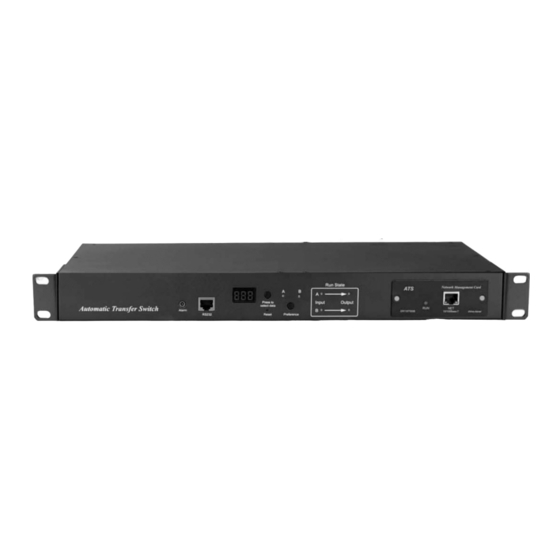
4. Product Schematic ① Alarm: the port of buzz and flesh, used to connect to external annunciator ② RS232: Serial communication port, connect the device to local PC ③ LED screen: display the current; voltage; IP address and hardware version ④... -
Page 6: Mounting Method
3. Four Ø 6 x 16 mm cross bolt 4. One user manual and CD 5. Optional accessories 5.1. Circuit breaker (either circuit breaker or surge protection) 5.2. Surge protection module (either surge protection or circuit breaker) 6. Mounting Method Horizontal rack mounting 7. -
Page 7: Ethernet Connection (Only Intelligent Type)
8. Ethernet connection (only intelligent type) Use supplied network cable, connect one side to the NET port of device and the other end to network. The software of hardware update method 9.1 Save the software update file provided by supplier to the local 9.2 Open the the software update file, double-click the setup.exe file to install. -
Page 8: Hyper Terminal User Guide
9.8 Click will be displayed on the interface if read success, if not, please double-check the cable connection and communication port. 9.9 Click will be displayed on the interface if erase success, if not, please double-check the cable connection and communication port. 9.10 Click will be displayed on the interface if loading success, if not, please double check the cable and... - Page 9 3. Enter one or several numbers at random when it require your area code, for instance 0755 and click OK. 4. Click OK, it pop-up the link description window as below: Enter a Name like ATS and click OK.
- Page 10 Select the COM port will be using and click OK. 7. Set the baud rate of ATS as 19200 and enter configuration information for data bits, parity and flow control as provided below, then click OK. If it is not the first time that the PC run the Hyper Terminal, it will goes directly to the window as the 4th item of this chapter, then follow up the instruction from the 4th to 7th and enter the Hyper Terminal monitoring interface as below:...
- Page 11 Setup ASCII code 9.1. Click the file in the main menu and select attributes or click on the icon directly. 9.2. Click on ASCII Setup. 9.3. Tick off the boxes as window above, then click the OK button and return to the monitoring interface.
- Page 12 11. View the ATS status Enter 1 and press Enter, the ATS status will be displayed in the interface as below: Device Manager: Device manager Source A Voltage: The voltage of the source A Source B Voltage: The voltage of the source B Output Current : The output current Selected Source : The current input power is source B Preferred Source: The preferred input power is source A...
- Page 13 12.1. Enter the corresponding code, for instance: Enter 1 then press Enter to select input A as the preferred power input. The interface will return to Device Manager interface. See the below window: Preferred Source: Source A means that input A was select as the primary power source 13.
- Page 14 Enter corresponding number to Re-define the item that user want to change, select 1 to set the minimum value of current to alarm; select 2 to set the maximum value of current to alarm; select 3 to set the minimum value of voltage to alarm;...
- Page 15 Enter the correct date format in the window. For instance 2010/07/22 The above window shows that the setting is a success. 15.2. Timing re-define the path are Main Menu=>3 (System Time) =>2 Enter the correct time form in the window; for instance 11:15:23 The above window show that the setting is a success.
-
Page 16: Software User Guide
9. Software user guide 1. Software Introduction ATS monitoring and management software using the embedded Web Server system, supports HTTP and SNMP. It helps to monitor the total load current; input/output of the voltage timely so that the user can manual or automatic switch the input power between source A and source B to ensure uninterrupted power supply of the crucial devices. -
Page 17: Access Method
2. Access method Connect the device to LAN or WAN, user can access and manage the device through Web and SNMP, please see detail information as below. 2.1 Web Device support HTTP protocol, we recommend user to access through IE 6.0, IE 7.0, IE 8.0, IE 9.0, Firefox and Google chrome, the Web access method are as below: Open the browser. -
Page 18: Device Status
2.1.1 Device Status Device Status interface display the status of the power input as well as the current & voltage status of the Device. 1. The Status section shows the current operating status of ATS: Green means OK; Red means abnormality; Grey means power failure. 2. -
Page 19: Threshold Setting
4. Buzzer alarm: Set to "off", the equipment alarm mute; set to "on", the device alarm buzzer. 5. Panel Lock: To luck or unlock the hardware. 2.1.3 Threshold Setting Threshold interface display user-defined minimum and maximum of current and voltage. 1. -
Page 20: User Manage
1. Click on Setting time to adjust the system time to PC time. 2. The alarm logs can be viewed from the alarm log down list. 3. The operate log from the drop down list can view the event logs like preferred source setting, re-transfer time settings and threshold settings. -
Page 21: Network Config
2.1.6 Network Config To configure the network like IP address, subnet mask, default gateway, DNS, HTTP port. Network Configuration 1. IP Address: default address is 192.168.1.163 2. Subnet Mask: default address is 255.255.255.0 3. Gateway: Default gateway is 192.168.1.1 4. DNS: Default one is 0.0.0.0 Note: Network configuration will take effect after restart. -
Page 22: Snmp Settings
2.1.7 SNMP Settings To configurate the SNMP and Telnet access method as below: 1. SNMP is enabled by default 2. Set “get” “set” character string to get and set community. getting the community is to offer read-only channel mark of visiting the MIB object, setting the community is to offer the read-write channel mark of visiting MIB object, TRAPPING the community is the style mark of all TRAP information generated and sent . -
Page 23: Email Alarm
2.1.8 Email alarm User can use the Simple Mail Transfer Protocol(SMTP) to send e-mail administrator when an event occurs. 1. E-mail is enabled by default 2. SMTP address is the outgoing email server address, support up to 25 character. E.g Sina SMTP address is smtp.sina.com; 3. -
Page 24: Restart
2.1.9 Restart User can restart the system or restore to factory settings in the Restart interface. Restart is to refresh the system software like changing the IP address, SMTP, HTTP port, restart the system will not affect the power supply. Reset system setting is to retore the system to default IP, system configuration, user name and password. - Page 25 1. SNMP software display the device information, power input information, status of the current /voltage and threshold information through mib description table format as below: Name Description sourceaname 1.3.6.1.4.1.30966.10.1.1.1 The name of power source A sourcebname 1.3.6.1.4.1.30966.10.1.1.2 The name of power source B prefered 1.3.6.1.4.1.30966.10.1.1.3 The preferred power source...
-
Page 26: Telnet Access
2.3 Telnet access The application of Telnet enable the user to remotely manager the PDU easily. The user can monitor and manage the device by entry the command line from the Telnet program. Telnet require the the customer terminal from the PC and there are free software like PUTTY available. The main command line are as following: STATUS, REBOOT, RESET, HELP A.
Need help?
Do you have a question about the DN-95639 and is the answer not in the manual?
Questions and answers