
Related Manuals for Digitus DN-95320-1


Summary of Contents for Digitus DN-95320-1
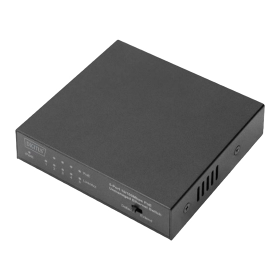
- Page 1 Fast Ethernet PoE Switch 4-port PoE + 1-port uplink, 60W PoE Budget Quick Installation Guide DN-95320-1...
-
Page 2: Copyright Statement
When switching into extend mode, Ports 2-5 can be switched into long range mode at up to 250 meters with 10 Mbps. The DN-95320-1 is easy to install and to use. It does not require any configuration or installation. With its desktop... - Page 3 1.1 Features PoE support: Port 1-4 (802.3 af/at) PoE total output: 60 watts 4 RJ45 PoE Ports An RJ45 port can also be used as an uplink port External power supply, sophisticated design, suitable for desktop installation LED displays: PoE, link, activity ...
-
Page 4: Hardware Specifications
1.3 Hardware Specifications IEEE802.3i, IEEE802.3u, Standards IEEE802.3x, IEEE802.3az, IEEE802.3at, IEEE802.3af 5 x 10/100Mbps Interface Auto-Negotiation ports Default mode:1-5 port speed rate 100 Mbps, communicate with each other Extend mode:1port speed rate Mode switch 100Mbps,2-5 PoE port rate of 10 Mbps, the farthest distance is 250m, communicate with each other... - Page 5 Dimensions (W x D x H) 89.3*81.7*21.3mm Operating Temperature: 0℃ - 45℃ Storage Temperature: -40℃ - 70℃ Environment Operating Humidity: 10%~90% RH non-condensing Storage humidity: 5%~90% RH non-condensing 1.4 External Component Description Front Panel The front panel of the Switch consists of one power LED indicator, five Link/Act LED indicators, four PoE LED indicators and one slide switch as shown as below.
- Page 6 You can with LED indicator quickly judge the Switch work, help diagnose problems in the Switch or the connected devices. LED indicator as shown below: LED indicators: The LED Indicators will allow you to monitor, diagnose and troubleshoot any potential problem with the Switch, connection or attached devices.
- Page 7 No PD is connected to the corresponding port, or there is a breakdown. PoE status A Powered Device is indicators Solid connected to the port, (2-5) orange which supply power successfully. The PoE power current Blinking may be overloaded Rear Panel The rear panel of the Switch consists of 5 x 10/100Mbps RJ- 45 ports and a power connector as shown as below.
-
Page 8: Installing And Connecting The Switch
Power Connector: Power is supplied through an external DC power adapter. It supports 53.5V DC. 2. Installing and Connecting the Switch This part describes how to install your PoE Ethernet Switch and make connections to it. Please read the following topics and perform the procedures in the order being presented. -
Page 9: Desktop Installation
2.2 Desktop Installation When installing the Switch on a desktop, please attach these cushioning rubber feet provided on the bottom at each corner of the Switch in case of the external vibration. Allow adequate space for ventilation between the device and the objects around it. - Page 10 2.5 Switch connection to the PD 2~5 port of the Switch have PoE power supply function, the maximum output power of single port up to 30W, it can make PD devices, such as internet phone, network camera, wireless access point work. You only need to connect the Switch PoE port directly connected to the PD port by network cable.
Need help?
Do you have a question about the DN-95320-1 and is the answer not in the manual?
Questions and answers