Advertisement
Quick Links
Owner's Manual
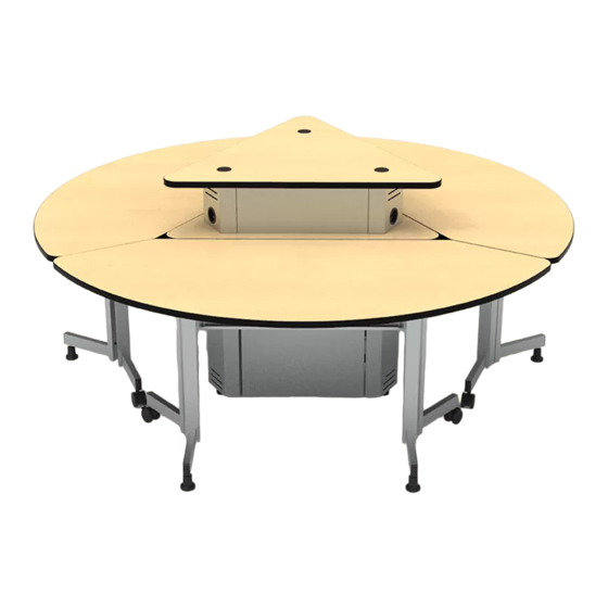
InVision Active Learning POD System ™
37109
Table
37110
Center Pedestal
37111
Pedestal Riser
37112
Modesty Panel
CAUTION:
Before using this product, read this manual and follow
all safety and operating instructions.
Before you begin, please make sure all parts and
proper quantities are included. Any parts damaged
during shipment must be reported within 15 days of
receipt. To report information regarding damages or if
you have any questions, please call 1-800-235-1262.
To purchase parts or accessories, please contact us at
www.spectrumfurniture.com
1-800-235-1262
Thank you for purchasing Spectrum products!
Spectrum Industries, Inc
Chippewa Falls, WI 54729, USA
InVision Active Learning
POD System
with optional
Pedestal Riser
0114246R1 Page 1 of 12
Advertisement

Related Manuals for Spectrum Industries InVision


Summary of Contents for Spectrum Industries InVision
- Page 1 Owner’s Manual InVision Active Learning POD System ™ 37109 Table 37110 Center Pedestal 37111 Pedestal Riser 37112 Modesty Panel InVision Active Learning POD System with optional Pedestal Riser CAUTION: Before using this product, read this manual and follow all safety and operating instructions.
-
Page 2: Hardware Package Contents
Hardware Package Contents Note: The items shown here represent all the structural components available for the InVision Active Learning POD System. Some of the items shown may not be included with your particular unit-some assembly steps may not apply. Before beginning assembly, please review these instructions. - Page 3 (1) 0113959 (2) 0113963 (1) 0113964 top panel shelf door stop bracket (1) 0113967 (2) 0113962 (3) 0113960 door assembly side panel corner column 37110 - Center Pedestal Parts Bag (20) 026064 (3) 037779 1/4-20 x 5/8” PHMS 5/16-18 x 1” glide (15) 0100167 (3) 0113961 8-32 x 1/2”...
-
Page 4: Assemble Legs
1. Table assembly - 37109 A. Assemble legs Note: Each table comes with Phillips (4) casters and (4) glides. The Screwdriver table can be assembled with all To make a leg assembly, attach a leg bracket (notches facing leg plates Figure 1B) 4 casters for frequent mobility, to two legs with (4) 1/4-20 x 5/8”... - Page 5 2. Center pedestal assembly - 37110 A. Choose pedestal top panel Phillips 7/16” or adjustable Glide wrench Screwdriver wrench (included) Option #1: Option #2: If you are assembling a standard (flush worksurface) table, install If you will be using the optional pedestal riser, install the open the solid top panel on the center pedestal.
- Page 6 B. Assemble pedestal Place the top panel face-down onto a non-abrasive surface. Figure 2C. Align and attach the corner columns to the top panel using 1/4-20 x 5/8” PHM screws. Do not tighten completely yet. Note: If you will be attaching the pedestal riser later with the open top panel, install (1) 1/4-20 x 5/8” PHM screw in the center mounting hole of each corner column.
- Page 7 Note: If you will be attaching the pedestal riser, install the door, but not the shelves, then proceed with the pedestal riser assembly instructions on p.8. Install the two adjustable shelves at the desired height and attach to the side panels with (4) 1/4-20 x 5/8” PHM screws and tighten securely.
- Page 8 3. Pedestal Riser Assembly - 37111 Note: If you are installing the pedestal riser onto an existing pedestal with a solid top panel: • The solid top panel must be removed and replaced with the open top panel prior to the riser assembly. (See step B1-B2 on p.6 for the open top panel assembly procedure.) •...
- Page 9 B. Install solid top panel and instrument panels 1. Set the solid top panel onto the corner columns while aligning the mounting holes. Figure 3B. Secure each corner column to the solid top with (2) 1/4-20 x 5/8” PHM screws and tighten securely. 2.
- Page 10 4. Modesty panel assembly - 37112 A. Install modesty panel Phillips 1. Carefully flip the table over onto a non-abrasive surface. Figure 4. Screwdriver 2. Remove the upper 1/4-20 x 5/8” PHM screw from each leg assembly. 3. Orient the modesty panel as shown while aligning the worksurface mounting holes. 4.
-
Page 11: Install Brackets
5. Connecting tables together (optional) A. Install brackets Phillips To connect the tables together, place all three tables around the module. Screwdriver Place the unit-to-unit bracket across the table seam and align with the worksurface mounting holes. Attach with (2) 1/4-20 x 5/8” PHM screws. Figure 5. Keep screws loose until all three tables are aligned and connected, then tighten securely. -
Page 12: Warranty
Warranty WE WILL MAKE IT RIGHT FOR YOU! Spectrum is committed to provide complete customer satisfaction. Each of our products are manufactured from the best materials available and each product is stringently monitored throughout the production process through our P.A.C.E. program (Product Assurance to meet Customer Expectations). Our Customer Service Help Line 1-800-235-1262 is ready to provide immediate attention to any questions, comments or concerns.
Need help?
Do you have a question about the InVision and is the answer not in the manual?
Questions and answers