Table of Contents
Advertisement
Quick Links
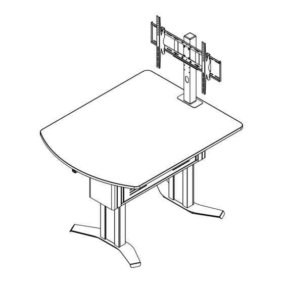
Owner's Manual
InVision Access Nano Table
37129
Important
Before using this product:
• Read this manual
• Comply with all safety and operating instructions
• Ensure all parts and correct quantities are included
Any parts damaged during shipment must be reported
within 15 days of receipt. To report information regard-
ing missing parts or damage, to purchase parts or
accessories, or if you have any questions, please
contact us.
Thank you for purchasing Spectrum products!
Spectrum Industries, Inc
925 First Avenue, Chippewa Falls, WI 54729 USA
800 235 1262
715 723 6750
www.spectrumfurniture.com
™
Shown with optional display stand
0118629R1 Page 1 of 13
Advertisement
Table of Contents

Related Manuals for Spectrum Industries InVision Access Nano Table 37129


Summary of Contents for Spectrum Industries InVision Access Nano Table 37129
- Page 1 Thank you for purchasing Spectrum products! Spectrum Industries, Inc 925 First Avenue, Chippewa Falls, WI 54729 USA 800 235 1262 715 723 6750 www.spectrumfurniture.com...
- Page 2 If servicing is necessary, please the power cord by pulling only on the cord. contact Spectrum Industries for assistance. • Do not step on, drive over, drag, or place objects on the power cord. • For added safety, plug the cart into a grounded outlet controlled by a GFI (Ground Fault Interrupter) circuit breaker.
- Page 3 Components (1) 0116814 (1) 0116818 Table core with set and go legs Table core with eLift legs (shipping position shown) (shipping position shown) Hardware (1) 0109398 (2) 037542 Control button #8 x 5/8” bracket PHSM (1) 0109397 (2) 0107023 Control button Snap-in pine tree clip (2) 037779...
-
Page 4: Assembly & Set-Up
Assembly / Setup 1. Unpack & detach from pallet Phillips screwdriver 1. Remove outer sleeve. Figure 1A. 2. Unscrew the (4) Phillips head wood screws securing the table core to the pallet. Figure 1B. 3. Without using a utility knife, open the rest of the boxes. Cordless drill with long magnetic (best) - Page 5 3. Adjust leg height (Set and go legs only) Phillips screwdriver Note: If you have a table with eLift legs, proceed to step 4. Cordless drill Tables with adjustable-height set and go legs can be with long magnetic adjusted to have a worksurface height between 29”- 42” (in (best) Phillips driver 1”...
-
Page 6: Install Worksurface
4. Flip Core upright 1. Carefully flip the table core upright-this will take 3-4 people. Figure 4.. Figure 4 5. Install worksurface Phillips screwdriver 1. Set the worksurface onto the the core and align the mounting holes. Figure 5. 2. Attach the worksurface using (8) 1/4-20 x 2-3/4” PHM screws. Worksurface 1/4-20 x 2-3/4”... -
Page 7: Display Stand
Optional 6. Display Stand Display Stand If you have the optional display stand, proceed with the installation at this time. Figure 6. (Instructions included with stand.) Cord management options Cords and wiring from any worksurface devices can be routed cleanly throughout the unit using grommet holes and openings in the bottom of the technology compartment. - Page 8 eLift operating instructions - eLift equipped tables only Phillips screwdriver 1. Attach the control button bracket under the radiused portion of the worksurface with (2) #8 x 5/8” PHSM screws and pre-drilled pilot holes in the center of the worksurface. 2.
- Page 9 Accessories (Available separately after initial configured purchased) Element Display Stand - 37130 • Bolts directly to worksurface • Integrated cable management routes and hides wires Display mount • Adjustable (VESA-compatible) mount • Requires worksurface mounting holes and cutout Monitor size range: 32”-55”...
-
Page 10: Safety Information
Electric leg information Warning! Only for EU markets • This appliance can be used by children aged from 8 years and above and persons Failure to comply with these instructions may result in accidents involving serious personal injury. with reduced physical, sensory or mental capabilities or lack of experience and Failing to follow these instructions can result in the product being damaged or being destroyed. - Page 11 Misc. on the DESKLINE® DL5/DL6 system Electrical connection of the DL5/DL6 system This system is a DESKLINE system developed for desks and for indoor use in offi ces. Do not The DESKLINE® DL5/DL6 system is to be connected as shown on fi gure 4. Each DL5/ use it in industrial kitchens or in other enviroments that have to be cleaned with aggressive DL6 is to be connected to the sockets on the control box by means of the motor cables, detergents.
-
Page 12: Reset Procedure
eLift Leg Troubleshooting Guide Symptom Problem Solution Loss of power Be sure unit is plugged into a live circuit. Loose electrical connections Make sure all electrical connections are securely plugged into the control box. 1. Raise the worksurface by pressing the “Up” button. Object encountered under 2. -
Page 13: Warranty
Warranty WE WILL MAKE IT RIGHT FOR YOU! Spectrum is committed to provide complete customer satisfaction. Each of our products is manufactured from the best materials available and each product is stringently monitored throughout the production process through our P.A.C.E. program (Product Assurance to meet Customer Expectations). We expressly warrant that Spectrum products will be of good quality and workmanship and free from defect for the period set out in the warranty table below from the date of delivery.
Need help?
Do you have a question about the InVision Access Nano Table 37129 and is the answer not in the manual?
Questions and answers