Table of Contents
Advertisement
Quick Links
Owner's Manual
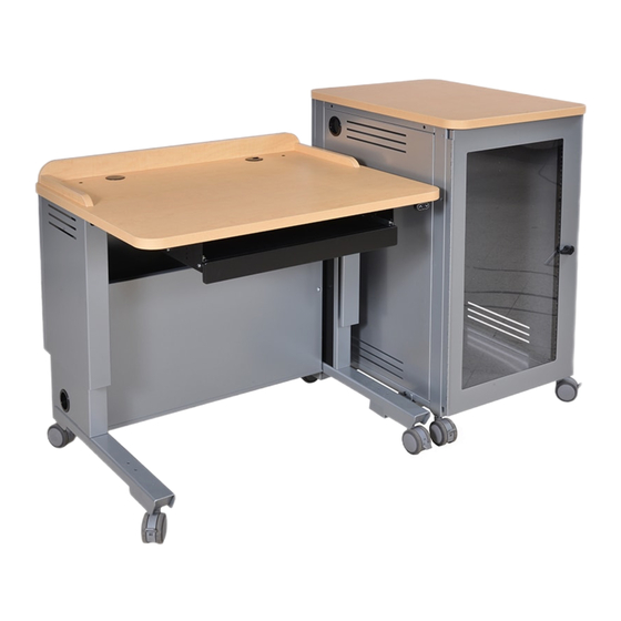
Freedom One eLift Lectern
55357
Important
Before using this product:
• Read this manual
• Comply with all safety and operating instructions
• Ensure all parts and correct quantities are included
Any parts damaged during shipment must be reported
within 5 days of receipt. To report information regarding
missing parts or damage, to purchase parts or acces-
sories, or if you have any questions, please contact us.
Thank you for purchasing Spectrum products!
Spectrum Industries, Inc
925 First Avenue, Chippewa Falls, WI 54729 USA
800 235 1262
715 723 6750
www.spectrumfurniture.com
™
0118408R12 Page 1 of 20
Advertisement
Table of Contents

Related Manuals for Spectrum Industries Freedom One eLift Lectern 55357


Summary of Contents for Spectrum Industries Freedom One eLift Lectern 55357
- Page 1 Thank you for purchasing Spectrum products! Spectrum Industries, Inc 925 First Avenue, Chippewa Falls, WI 54729 USA 800 235 1262 715 723 6750 www.spectrumfurniture.com...
- Page 2 16. This unit does not have any user-serviceable parts. If servicing is necessary, please 13. Damaged electrical components can create signifi cant hazards to users and is not contact Spectrum Industries for assistance. covered by the warranty. Repairs should always be performed by a qualifi ed electrician.
- Page 3 Hardware Equipment Rack (included with select configurations) (2) 0190604 (4) 055194 3” Swivel Stem Casters with brake Glide (1/2-13 x 1” thread) (1/2-13 thread) (only included with units configured with glides) (2) 0190603 3” Swivel Stem Casters (1/2-13 thread) Unit-to-Unit Brackets (included with select configurations) (2) 0118062 (4) 052605...
-
Page 4: Normal Operation
Assembly / Setup 1. Lectern lift mechanism initial setup, operation, and reset procedure Preparation: Control buttons • Read all instructions before operation. • Make sure lectern is plugged-in using the 15-foot, 15-amp power cord. • Locate the “Up” and “Down” control buttons. Control pad is located on the instructor- side under the worksurface front edge on opposite side from rack cabinet. - Page 5 2. Attach equipment rack casters / glides ” for casters ” On a non-abrasive surface, carefully tip the equipment rack onto its back (audience side). Figure 2. for glides Install the included stem casters or glides and tighten securely. Note: 2 locking casters should be installed on the instructor-side for easy-access. Tip the equipment rack back upright.
- Page 6 3. Connect lectern and equipment rack Determine which side of the lectern the equipment rack is to be installed (left or right side). (Right-side installation shown.) Attach the unit-to-unit brackets to the equipment rack side panel mounting holes with (4) 1/4-20 x 15mm JC bolts. Figure 3A. Equipment Rack (2) 1/4-20 x 15mm JC bolts...
- Page 7 Installing flip-up shelf (select units) 1. Determine which side of the equipment rack the shelf is to be installed. 2. Extend and lock the folding shelf brackets into the horizontal position. Figure 4A. 3. Align and attach each bracket to the side of the lectern with (2) 8-32 x 3/8” PHM screws and tighten securely.
- Page 8 Overbridge insert panel (select overbridge lecterns) 4mm hex Drill wrench 1. To remove the overbridge insert panel, remove the (2) 1/4-20 x 35mm JC bolts with a 4mm hex wrench and lift out the panel. Figure 5A. Measuring Drill bit 2.
- Page 9 Freedom One eLift Overbridge Insert Panel Blank (flat view) 2” grommet 2” grommet Cutouts should Max cutout area be avoided here if device will descend below worksurface (Actuator plug below worksurface) Worksurface opening below Figure 5B Overbridge section view Worksurface opening below Figure 5C 0118408R12 Page 9 of 20...
-
Page 10: Wiring Diagram
Wiring Diagram Up / Down buttons Actuator Actuator Wire Loom To wall outlet Control Box Figure 6 Note: The shroud panel can be removed with 2 screws and / or the worksurface extended to access internal wiring. 0118408R12 Page 10 of 20... - Page 11 Removing equipment rack audience-side panel The audience-side panel can be removed to access the rear portion of the equipment rack. To remove the panel, remove the (2) 1/4-20 x 5/8” PHM screws under the worksurface edge. Figure 7. Let the panel drop slightly from the 4 installed frame screws, then remove the panel. To reattach, align the 4 keyhole slots with the installed frame screws, and push the panel up to the work- surface.
- Page 12 Accessories (Customer-installed when purchased separately) Overbridge Insert Panel-Large - 96507 Unit-to-Unit Connector Kit - 55359 Customized Logo Panel - 55380 Two-piece Overbridge Insert Panel-Large - 96513 • For connecting equipment rack to lectern • To get a customized logo panel, contact •...
- Page 13 Keyboard Tray - 55379 Power Module - 99058 • (2) AC power receptacles • Requires worksurface cutout • Tray can be installed and used as a keyboard tray or flipped and used as a • (2) USB charge ports • ETL-certified storage drawer using pre-drilled mounting holes under the lectern worksurface.
- Page 14 Rechargeable Battery Pack System - 99045 • Creates a mobile lectern / desk by providing the ability to operate the unit in locations without AC power • Compact, lightweight lithium-ion battery plugs into and charges from the existing lectern control box •...
- Page 15 EM Wireless Charging Pad - 99057 • Uses electromagnetic technology to charge Qi V1.2 compliant IC devices ("Qi" enabled) • LED to confirm pairing / charging • Security tab prevents theft • Requires 3” round cutout to be made by customer •...
-
Page 16: Rack-Mount Accessories
Rack-mount Accessories Cantilever Shelf - 2RU - 97504 Cantilever Shelf - 3RU - 97502 • 16ga steel • 16ga steel • Shelf: 17.5”W [44.45 cm] x 18”D • Shelf: 17.5”W [44.45 cm] x 18”D [45.7 cm] x 3.5”H [8.89 cm] [45.7 cm] x 5.25”H [13.33 cm] •... -
Page 17: Safety Information
Electric actuator information Warning! Only for EU markets • This appliance can be used by children aged from 8 years and above and persons with Failure to comply with these instructions may result in accidents involving serious person- reduced physical, sensory or mental capabilities or lack of experience and knowledge if al injury. - Page 18 Misc. on the DESKLINE® DL5/DL6 system Electrical connection of the DL5/DL6 system This system is a DESKLINE system developed for desks and for indoor use in offi ces. Do The DESKLINE® DL5/DL6 system is to be connected as shown in Figure 4. Each DL5/ not use it in industrial kitchens or in other enviroments that have to be cleaned with ag- DL6 is to be connected to the sockets on the control box by means of the motor cables, gressive detergents.
- Page 19 Freedom One eLift Lectern Troubleshooting Guide Symptom Problem Solution Loss of power Be sure control box is plugged into a live circuit. Make sure all electrical connections are securely plugged into the control box. Loose electrical connections See wiring diagram on p.10 for reference. 1.
-
Page 20: Warranty
5 Years Customer supplied material No Warranty DESIGNED AND ASSEMBLED IN CHIPPEWA FALLS WISCONSIN.USA 925 FIRST AVENUE, CHIPPEWA FALLS, WI 54729 / 800-235-1262 / 715-723-6750 / WWW.SPECTRUMFURNITURE.COM © 2019 Spectrum Industries Inc., All rights reserved. 0118408R12 Page 20 of 20...
Need help?
Do you have a question about the Freedom One eLift Lectern 55357 and is the answer not in the manual?
Questions and answers