Advertisement
Quick Links
Owner's Manual
InVision Element Table
37128
Important
Before using this product:
• Read this manual
• Comply with all safety and operating instructions
• Ensure all parts and correct quantities are included
Any parts damaged during shipment must be reported
within 5 days of receipt. To report information regarding
missing parts or damage, to purchase parts or acces-
sories, or if you have any questions, please contact us.
Thank you for purchasing Spectrum products!
Spectrum Industries, Inc
925 First Avenue, Chippewa Falls, WI 54729 USA
800 235 1262
715 723 6750
www.spectrumfurniture.com
™
0118729R2 Page 1 of 11
Advertisement

Related Manuals for Spectrum Industries InVision Element Table 37128


Summary of Contents for Spectrum Industries InVision Element Table 37128
- Page 1 Thank you for purchasing Spectrum products! Spectrum Industries, Inc 925 First Avenue, Chippewa Falls, WI 54729 USA 800 235 1262 715 723 6750 www.spectrumfurniture.com...
- Page 2 If servicing is unplug by pulling only on the cord. necessary, please contact Spectrum Industries for assistance. • Do not step on, drive over, drag, or place objects on power cords. • For added safety, plug into a grounded outlet controlled by a GFI (Ground Fault Interrupter) circuit breaker.
- Page 3 Components Standard Worksurface 60”L x 42”W worksurface 72”L x 42”W worksurface 96”L x 42”W worksurface • Blank 0118512 0118518 0118549 • 1 Cove cutout 0118513 0118519 0118550 • 2 Cove cutouts 0118514 0118520 0118551 • Display Stand cutout 0118515 0118521 0118552 •...
- Page 4 T-Leg Components Corner Post Components (See p.5 for assembly) (See p.6 for assembly) (4) 037779 (4) 037779 5/16-18 Glide 5/16-18 Glide (20) 026064 (44) 026064 1/4-20 x 5/8” 1/4-20 x 5/8” PHMS PHMS (2) T-Leg assembly (20) 0100167 (4) Post Leg assembly (2) 0100167 8-32 x 1/2”...
-
Page 5: Assembly & Set-Up
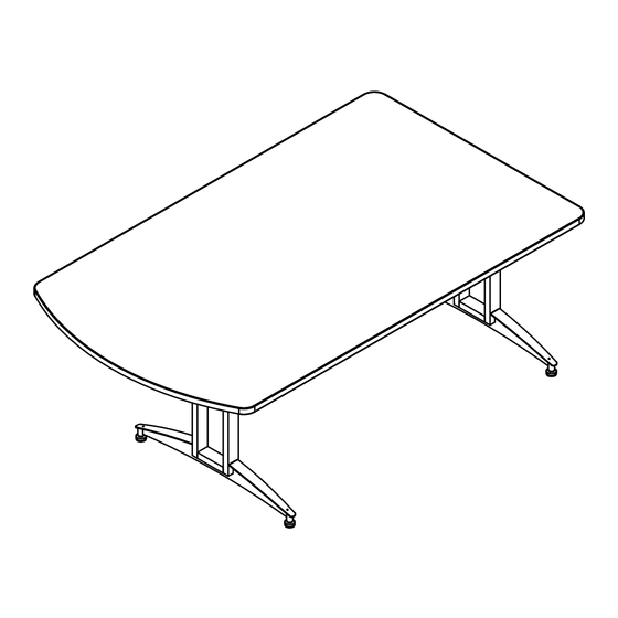
Table with T-Legs and Wire Tray Assembly / Setup 1. Attach T-Legs to worksurface Phillips Glide screwdriver 1. Place the worksurface upside-down (laminate side-down) onto a flat, non-abrasive surface like another table. Figure A1. 2. Attach the two T-legs as shown with 1/4-20 x 1-3/4” PHM screws. T-leg Cordless drill with Make sure the holes on the vertical leg tubes face inward. - Page 6 Table with Post Legs and Wire Tray Assembly / Setup 1. Attach Post legs to worksurface Phillips Glide screwdriver 1. Place the worksurface upside-down (laminate side-down) onto a flat, non-abrasive surface like another table. Figure B1. 2. Attach each post leg as shown with (8) 1/4-20 x 5/8” PHM screws. Cordless drill with 3.
- Page 7 3. Flip Table upright 1. Carefully flip the table upright-this will take 3-4 people. Figure 3. 2. If necessary, adjust glides to level table. CAUTION Do not allow the legs to contact the floor until the table is completely rotated. Side-loading of the table legs could cause damage.
- Page 8 Table with T-Legs and AV Equipment Channel Assembly / Setup 1. Assemble AV Equipment Channel Phillips screwdriver 1. Attach the front and rear uprights to the lower channel with 1/4-20 x 5/8” PHM screws. (10 per upright). Figure C1. 2. Tighten securely. Rear Upright Cordless drill with 3.
-
Page 9: Side Panels
3. Attach Worksurface Phillips screwdriver 1. Move leg assembly into the final location in the room. 2. Set the worksurface onto the assembled legs and align mounting holes. Figure C3.1. 3. Install (4) 1/4-20 x 40mm JC bolts through each leg to secure the worksurface. Figure C3.2. Cordless drill with 4. - Page 10 Accessories (Available separately after initial configured purchase) Element Display Stand - 37130 • Bolts directly to worksurface • Integrated cable management routes and hides wires Display stand • Adjustable (VESA-compatible) mount • Requires worksurface mounting holes and cutout Monitor size range: 32”-55”...
-
Page 11: Warranty
• 10 Years • Cart Chassis • Lectern Chassis DESIGNED AND MANUFACTURED IN CHIPPEWA FALLS WISCONSIN.USA 925 FIRST AVENUE, CHIPPEWA FALLS, WI 54729 / 800-235-1262 / 715-723-6750 / WWW.SPECTRUMFURNITURE.COM © 2015 Spectrum Industries Inc., All rights reserved. 0118729R2 Page 11 of 11...
Need help?
Do you have a question about the InVision Element Table 37128 and is the answer not in the manual?
Questions and answers