Advertisement
Quick Links
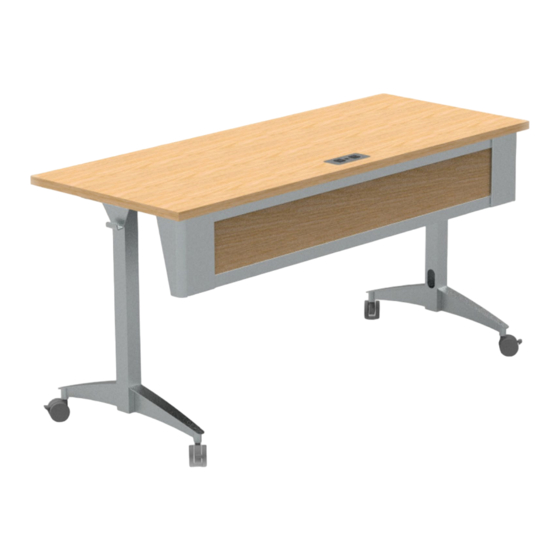
Owner's Manual
Owner's Manual
Flex Active Table
37239
Important
Before using this product:
• Read this manual
• Comply with all safety and operating instructions
• Ensure all parts and correct quantities are included
Any parts damaged during shipment must be reported
within 5 days of receipt. To report information regarding
missing parts or damage, to purchase parts or acces-
sories, or if you have any questions, please contact us.
Thank you for purchasing Spectrum products!
Spectrum Industries, Inc
925 First Avenue, Chippewa Falls, WI 54729 USA
800 235 1262
715 723 6750
www.spectrumfurniture.com
™
(Shown with glides)
(Shown with casters, Cove
module and modesty panel)
0190534R3 Page 1 of 10
Advertisement

Related Manuals for Spectrum Industries Flex Active Table 37239


Summary of Contents for Spectrum Industries Flex Active Table 37239
- Page 1 Thank you for purchasing Spectrum products! Spectrum Industries, Inc 925 First Avenue, Chippewa Falls, WI 54729 USA 800 235 1262 715 723 6750 www.spectrumfurniture.com...
- Page 2 • Do not step on, drive over, drag, or place objects on power cords. necessary, please contact Spectrum Industries for assistance. • For added safety, plug into a grounded outlet controlled by a GFI (Ground Fault Interrupter) circuit breaker.
- Page 3 Assembly / Setup Assembly / Setup Phillips Cordless drill screwdriver with Phillips driver 1/2” (best) wrench 1. Attach worksurface brace 1. Attach worksurface brace 2. Install glides or casters 2. Install glides or casters 1. Place the worksurface face down (laminate side-down) onto a flat, 1.
- Page 4 4. Install modesty panel - Optional 4. Install modesty panel - Optional 1. Orient the modesty panel and corners as shown and lock together. 2. Place a mounting bracket inside each panel opening. Figure 4.1. Figure 4.2. o r n a n e h t C t y P...
- Page 5 5. Install modesty panel - Optional 5. Install modesty panel - Optional 1. Orient the modesty panel and corners as shown and lock together. Figure 5. (2) 1/4-20 x 5/8” PHMS Figure 5 6. Flip table upright 6. Flip table upright 1.
- Page 6 Ganging latch installation - 37238 - Optional Ganging latch installation - 37238 - Optional 1. Place two tables next to each other. (1) 0190421 2. Open the latch and attach to table #1 with (2) #8 x 3/4” PHSM screws. Keeper #1 (1) 0190420 Figure 6.1.
- Page 7 “Easy Power Connection” installation - Optional “Easy Power Connection” installation - Optional 1. Remove locking tabs from the Cove module and place 2. Replace locking tabs and secure with thumbscrews. Figure 7.2. into the worksurface cutout. Figure 7.1. “Easy Power” Cove Module Cove Module Worksurface Thumbscrews...
- Page 8 ™ Cove Cove Power Module installation - Optional Power Module installation - Optional 1. Remove locking tabs from the Cove module. 3. Replace locking tabs and secure with thumbscrews. Figure 8.2. 2. Insert the power cord through worksurface cutout and place the Cove module into the cutout.
- Page 9 Accessories Accessories (Available separately (Available separately after after initial configured purchased) initial configured purchased) Modesty Panel 37234 - (for 48"W table) 37235 - (for 60”W table) 37236 - (for 72"W table) • 16 ga steel • 9”H panel attaches to worksurface •...
-
Page 10: Warranty
For a listing of all product specifi c warranty terms please visit our website at: https://www.spectrumfurniture.com/en/resources/purchasing-terms-warranty 1-800-235-1262 Toll-free HELPLINE spectrum@spectrumfurniture.com 925 FIRST AVENUE, CHIPPEWA FALLS, WI 54729 / 800-235-1262 / 715-723-6750 / WWW.SPECTRUMFURNITURE.COM © 2020 Spectrum Industries Inc., All rights reserved. 0190534R3 Page 10 of 10...
Need help?
Do you have a question about the Flex Active Table 37239 and is the answer not in the manual?
Questions and answers