Table of Contents
Advertisement
Quick Links
Advertisement
Table of Contents

Related Manuals for Agilent Technologies Pump Module


Summary of Contents for Agilent Technologies Pump Module
- Page 1 Pump Module User Guide Original Instructions Agilent Technologies...
- Page 2 Notices © Agilent Technologies, Inc. 2014 Warranty (June1987) or DFAR 252.227-7015 (b)(2) (November 1995), as applicable in any No part of this manual may be reproduced The material contained in this docu- technical data. in any form or by any means (including ment is provided “as is,”...
-
Page 3: Table Of Contents
“Maintenance and troubleshooting” on page 27 For instructions on how to configure the autofilling parameters and how to use the Pump Module in a protocol, see the user documentation for your automation software and liquid- handling device. You can search the product knowledge base or download... -
Page 4: General Safety Information
General safety information Before installing and using the Pump Module Before installing and using the Pump Module, make sure you are aware of the potential hazards and understand how to avoid being exposed to them. You must be properly trained in the correct and safe installation and operation of the device. - Page 5 Failure to comply with these precautions violates safety standards of design and the intended use of the product. Agilent Technologies assumes no liability for the customer’s failure to comply with these requirements.
- Page 6 Ensure that liquid does not contact the device electronics. Periodically inspect the tubing for leaks. CAUTION Do not lift the Pump Module by the peristaltic pumps that are mounted on the front of the device. Doing so could damage the Pump Module. Pump Module User Guide...
- Page 7 Safety and regulatory compliance Compliance standards The Pump Module complies with the applicable EU Directives and bears the CE mark. See the Declaration of Conformity or Declaration of Incorporation, as applicable, for details. The Pump Module is designed to comply with the regulations and standards listed in the following table.
-
Page 8: Laboratory Setup Requirements
Laboratory setup requirements Placement considerations The Pump Module must be located near a power source to connect the power cord, and near the controlling liquid- handling device to connect the communication cable. If applicable, the Pump Module must be positioned to enable connecting the cable from the Agilent Weigh Station, Weigh Pad, or Weigh Shelf. - Page 9 100–240 V~, 50/60 Hz, 1.5 A Environmental requirements Ambient environment The Pump Module is for indoor use only. The following table lists the operating and storage specifications. If you have integrated devices, your system might require additional cooling depending on the number and types of integrated devices.
-
Page 10: Pump Module Overview And Components
Optionally, you can use the Pump Module with an Agilent Weigh Station, Weigh Shelf, or Weigh Pad to provide precise liquid- level control for an autofilling reservoir or wash station. -
Page 11: Autofilling Options
COM OUT Connects the communication cable from one Pump Module port to another Pump Module in a series. Up to five Pump Modules and three Weigh Stations can be connected and controlled through one liquid- handling device. For details, “Connecting power and communication” on page... - Page 12 Figure Auto Filling Reservoir Item Description Inlet ports. Connects to the input tubing from the Pump Module that fills the reservoir. Outlet port. Connects to the output tubing from the Pump Module that empties the reservoir.
- Page 13 The chimneys in the wash station prevent carryover and reduce contamination. The Pump Module pumps wash liquid into the Tip Wash Station through two inlet ports. The wash liquid flows up through the chimneys in the Tip Wash Station to wash the tips.
- Page 14 Pump Module User Guide Autofilling options Figure 8-Channel Wash Station: side view and top view Item Description Inlet port. Fills the wash station. Liquid flows up through the eight channels. Outlet port. Empties the wash station. The fluid in the waste trough flows out through this port.
- Page 15 Plugged Connected to output port (empty) tubing When properly configured in the automation software, the Pump Module automatically fills and drains the reservoir. The Open Wash Reservoir can be set up to run in either of two modes: • Overflow mode. Fresh wash solution enters the reservoir from the two inlet ports (1), overflows into the overflow trough, and is pumped through the two outlet ports (2) to waste.
-
Page 16: Setup Workflow
Pump Module User Guide Setup workflow Setup workflow This topic describes the workflow for setting up an Agilent autofilling reservoir or wash station on an Agilent liquid- handling device using the Pump Module. Step Procedure See… Ensure that you are familiar with “Autofilling options”... -
Page 17: Connecting Power And Communication
Connecting power and communication Before you begin • Ensure that the Pump Module location meets the site requirements. See “Laboratory setup requirements” on page • Make sure you have the Pump Module power cord and communication cable. WARNING Ensure that the power cords are in good condition and are not frayed. - Page 18 50/60Hz 1.5 Amps To connect multiple Pump Modules, use a second serial cable to connect the COM OUT port on the first Pump Module to the COM IN port on the second Pump Module. CAUTION Ensure that the communication cable plug that has the EMI filter is connected to the Pump Module COM IN port.
-
Page 19: Routing The Tubing
Routing the tubing About this topic This topic explains how to route the tubing from the reservoir or wash station to the Pump Module and source and waste containers. This topic includes the following sections: • “Before you start” on page 17 •... - Page 20 Pump Module User Guide Routing the tubing Figure Example tubing configuration for (A) Tip Wash Station and (B) 8-Channel Wash Station Item Component Description Source Supplies the fill liquid for an autofilling wash station, bottle such as the Tip Wash Station or 8- Channel Wash Station.
- Page 21 Tip Wash Station. Workflow for routing the tubing WARNING Ensure that the Pump Module and the liquid-handling device are turned off before routing the tubing. Perform the following procedures in the order given: Step For this task...
- Page 22 Pump Module User Guide Routing the tubing To connect tube A to a reservoir or wash station on a platepad or Weigh Station: Fill (input). Cut three lengths of tube A. Two lengths of tubing are for the measured distance from the reservoir input ports (1) to a 3- way connector (2).
- Page 23 Pump Module User Guide Routing the tubing Figure Example tubing configuration for Vertical Pipetting Station with Tip Wash Station 00299 Connecting tube A to the 8-Channel Wash Station Refer to the following figure for this procedure. To connect tube A to an 8-Channel Wash Station: Fill (input).
- Page 24 In the following figure, the lower pump head controls the output flow to the reservoir, and the upper pump head controls the input flow. 96AM Wash Station. Agilent Technologies recommends using the lower pump for the output and the upper for the input as the figure shows.
- Page 25 Tip Wash Station as the preceding figure shows. Ensure that the filter is oriented so that the three thumbscrews face toward the Pump Module and the other side of the filter faces toward the Tip Wash Station. Insert a tubing connector (4) on each open end of tube B, as the preceding figure shows.
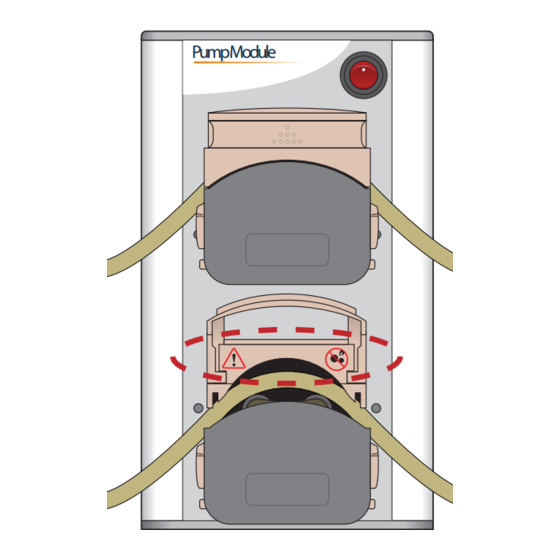
- Page 26 When using Marprene tubing, reset the tension after you run the Pump Module for the first 30 minutes. To reset the tension on the tubing, open the flip- top cover of the pump head, allow the tube to settle naturally across the rollers, and then reclamp the tube.
-
Page 27: Installing A Weigh Station
A Weigh Station measures the weight of a Agilent autofilling reservoir that is placed on it. When appropriately configured in the software, the Weigh Station works with the Pump Module to ensure that the reservoir is filled to a constant liquid level during the pump reagent task in a protocol. By monitoring the weight of the reservoir that sits on it, the Weigh Station controls when the Pump Module is activated. - Page 28 Before you start Determine where to install the Weigh Station. The Weigh Station must be close enough to the Pump Module, so that the Weigh Station cable can be connected to the Pump Module SHELF A port. Make sure you have the following: •...
-
Page 29: Maintenance And Troubleshooting
“Pump head tube size adjustment” on page 29 • “Reporting problems” on page 30 Periodic maintenance and inspection Periodically, perform the routine maintenance listed below. Your schedule might vary depending on the frequency of Pump Module use. Maintenance task Schedule Symptoms Clean the Pump Module using... - Page 30 WARNING Ensure that the Pump Module is turned off before you clean the device. CAUTION Use only recommended cleaning materials. Using other cleaning solutions and materials can damage the device. Do not use abrasive, corrosive cleaning agents. Do not use metal brushes.
- Page 31 “Pump head tube size adjustment” on page IMPORTANT When the Pump Module is not in use, lift the flip- top cover on each pump head to prevent flattening the tubing and to help maximize the tubing life.
- Page 32 Pump Module User Guide Maintenance and troubleshooting Carefully lower the cover to clamp the tube in place. When the pump head top closes on the tubing, the tubing is clamped and stretched to locate it in the correct position and with the correct tension.
- Page 34 Agilent Technologies User Guide G5406-90001 Revision C, September 2014...