SICK GM901 Operating Instructions Manual
Carbon monoxide measuring device
Hide thumbs
Also See for GM901:
- Manual (24 pages) ,
- Operating instructions manual (78 pages) ,
- Operating instructions manual (94 pages)

Related Manuals for SICK GM901


Summary of Contents for SICK GM901
- Page 1 Titelseite O P E R A T I N G I N S T R U C T I O N S GM901 Carbon Monoxide Measuring Device Installation Operation Maintenance...
- Page 2 Original Documents The English edition 8008250 of this document is an original docu- ment of SICK AG. SICK AG assumes no liability for the correctness of an unauthor- ized translation. Please contact the manufacturer or your local representative in case of doubt.
-
Page 3: Table Of Contents
5.3.1 Conditions for the zero-point adjustment ............... 31 5.3.2 Establishing the zero-point comparison path ..............31 5.3.3 Start the zero-point and check-point adjustment............32 5.3.4 Mounting the GM901 CO Monitor on the duct ............... 32 808250/2012-10 © SICK AG • Germany · All rights reserved... - Page 4 9.3.5 Communication Error Between the Evaluation Unit and Receiver........ 69 9.3.6 Sensor Values ........................69 9.3.7 Remote Diagnosis......................69 10 Spare Parts, Accessories....................71 10.1 Spare Parts........................71 10.2 Options, Accessories......................71 © SICK AG • Germany · All rights reserved 808250/2012-10...
- Page 5 Purpose of this document Purpose of This Document This instruction manual describes the standard scope of supply of the GM901 CO Measur- ing System, as well as the standard range of accessories available. The purpose of this doc- ument is to explain the functioning of the GM901 and describe the procedures for mounting, installing, starting up, and operating the device.
-
Page 6: Safety Information
Safety Information Intended Use The GM901 CO Analyzer must only be used to monitor CO concentrations in gas ducts. If the device is used for any other purpose or changed in any way, also during installation and as- sembly, any warranty claims vis-à-vis SICK AG will be rendered invalid. -
Page 7: Safety Devices And Measures
Please observe safety regulations at all times to prevent accidents. If the GM901 is used as a sensor in conjunction with a control system, the operator must make sure that a failure or malfunction cannot lead to operating conditions that cause dam- age or lead to other hazardous operating conditions. -
Page 8: Gm901 Overview
Cable 15 m (49 ft; CAN bus) Evaluation unit Connection unit (optional) PROFIBUS (when available) 1 Analog input 1 Analog ouput Power supply: 115/230 V AC Fig. 1 Components overview © SICK AG • Germany · All rights reserved 8008250/2012-10... -
Page 9: Standard Scope Of Supply
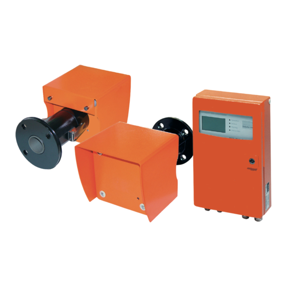
Evaluation unit Sender Fig. 2 CO Measuring Device GM901 The basic configuration of the GM901 consists of: • Sender • Receiver • Evaluation unit with connecting cable (2 m/6.6 ft) • Cable for connecting the sender and receiver units (15 m/50 ft) Optional Accessories •... -
Page 10: Profibus Interface
Note Available measuring data The measuring values provided by the GM901, serving as pathway to the process ma- nagement level are defined in the device master data file (GSD). You find the measuring sizes and their corresponding measuring unit in the table below:... -
Page 11: Mounting
Mounting for mounting position (1.4”) (1.2”) (18.5”) Flange 60 x 8 x 60 (2”) DIN 174 Steel tube 50 x 5 DIN 2391 Fig. 5 Recommendation for mounting the flange 8008250/2012-10 © SICK AG • Germany · All rights reserved... -
Page 12: Mounting The Standard Flange
When using the alignment device, attach the light source and receiver unit as shown in Fig.7 1. Align flange 1 until the light spot from the light source is at the center of the alignment target on the receiver unit. Tack-weld flange 1. © SICK AG • Germany · All rights reserved 8008250/2012-10... -
Page 13: Defining The Measuring Path
Keep the measurements for commissioning. 3.1.3 Variant Installation for Brick Ducts For brick ducts, the customer must attach suitable armature plates to the duct wall and weld the flanges with tube onto them 8008250/2012-10 © SICK AG • Germany · All rights reserved... -
Page 14: Variant Installation For Thin-Walled Ducts
Marking of (attached by customer) the mounting position xxxx The rear of the threaded pins is used for securing the optional weatherproof cover Fig. 10 Example of reinforced mounting location © SICK AG • Germany · All rights reserved 8008250/2012-10... -
Page 15: Mounting The Purge Air Unit
Secure lock angle with bolts onto the basis plate of the purge air unit. pipes ▸ Mount the cover ▸ Insert the locking bolts positionend at each side in to their counter piece, turn until it has snapped in. 8008250/2012-10 © SICK AG • Germany · All rights reserved... -
Page 16: Mounting The Co Measuring Device Gm901
Laser Gas Analyzer Mounting the CO Measuring device GM901 To ensure that the GM901 is installed and started correctly, the unit should be adjusted first. A CO-free environment is required for this zero-point adjustment. If the installation is not in operation and the duct is free of CO, the adjustment can also be carried out at the measuring point. -
Page 17: Aligning The Optical Axis
Secure the adjustment tube to the receiver using the clamps on the purge-air attach- ment. X/Y adjustment Alignment tube Ground glass screen Clamp Nuts for adjusting the optical axis Fig. 15 Aligning the optical axis between the sender and receiver 8008250/2012-10 © SICK AG • Germany · All rights reserved... -
Page 18: Mounting The Sender And Receiver
Mounting the sender and receiver GM901 sender or receiver Purge-air connection Purge-air attachment Fig. 16 Mounting the GM901 ▸ Remove the alignment device and secure the sender and receiver into position using the clamps © SICK AG • Germany · All rights reserved 8008250/2012-10... -
Page 19: Installing The Weatherproof Cover For The Gm901
Step 3 Fig. 17 Installing the weatherproof cover for the GM901 1. Mount the baseplate sideways on the flange with tube and secure it to the surface of the flange plate on the duct (purge-air attachment) using the threaded pins provided. -
Page 20: Mounting The Evaluation Unit
Secure the evaluation unit at with suitable bolts at 4 fastening brackets. 4 Mounting drill holes 7.2 mm (0.28 in) Mounting surface Fastening brackets Fig. 18 Mounting the evaluation unit © SICK AG • Germany · All rights reserved 8008250/2012-10... -
Page 21: Electrical Installation
• The evaluation unit has a separate mains switch. The following must be provided by the customer: The power supply for the GM901 and purge-air unit (3-phase) Signal cables suitable for the application PE conductors for connecting to the exterior of the connection unit (in accordance with... -
Page 22: Electric Wiring For Standard Version
Malfunction PROFIBUS (when available) 1 Analog input 1 Analog output Power supply: 115/ 230 V AC Fig. 19 Electrical connection GM901 (standard) ▸ Connect system components according to Fig. 19. © SICK AG • Germany · All rights reserved 8008250/2012-10... -
Page 23: Electrical Wiring For Evaluation Unit
1 Analog input 1 Analog output Power supply: 115/230 V AC Fig. 20 Connection unit at distances of up to 1,000 m (3,281 ft) ▸ Connect system components according to Fig. 20 8008250/2012-10 © SICK AG • Germany · All rights reserved... -
Page 24: Electrical Connections For The Purge Air Motor
Connection to low-pressure monitor Delta connection Star connection U2 V2 U2 V2 V1 W1 V1 W1 Starting circuit-breaker Connection for fan motor Fig. 21 Electrical connections for the purge-air supply © SICK AG • Germany · All rights reserved 8008250/2012-10... - Page 25 If the motor is rotating in the wrong direction, the purge-air fan sucks gas out of the duct and ATTENTION can irreparably damage the device and purge-air unit. If necessary, swap the voltage con- nections for the motor. 8008250/2012-10 © SICK AG • Germany · All rights reserved...
-
Page 26: Power Supply And Signal Cables For The Evaluation Unit
P E N L1 Connection Receiver Do1: Error DO2: Limit value Fig. 22 Electrical connection – standard (customer provided) Note The factory setting of the evaluation unit is 230 V AC © SICK AG • Germany · All rights reserved 8008250/2012-10... -
Page 27: Electrical Wiring Of The Evaluation Unit - Profibus
Fig. 23 Electrical connection to the connection unit – PROFIBUS (customer provided) Note The factory setting of the evaluation unit is 230 V AC 8008250/2012-10 © SICK AG • Germany · All rights reserved... -
Page 28: Electrical Connections Inside The Connection Unit
Connecting the evaluation unit - terminal strip ST 5 Cable length: max. 1000 m (3,280 ft) CAN-H / CAN-L / CAN GND Connecting the GM901 receiver - terminal strip ST 6 or ST 7 Standard cable (17 m/55.8 ft)) +24 V... -
Page 29: Commissioning
Measur i ng Measuring T=150 °C T=150°C 1128 mg/Nm Actual measuring value 1128 Start value of the measuring range 2000 2000 End value of the measuring range, adjustable Adjustable limit values 8008250/2012-10 © SICK AG • Germany · All rights reserved... -
Page 30: Function Keys And Sub Menus
Maintenance mode • Test Analog Outputs Checking current values at analog output • Test Relays Relais test • Reset Parameter Resetting of parameters to default value Measurement • Measuring meas © SICK AG • Germany · All rights reserved 8008250/2012-10... -
Page 31: Zero-Point Adjustment
30 minutes • Never change the alignment of the mounting brackets during the zero-point adjustment Once fitted to the duct the purge air attachments of the GM901, a new adjustment needs Note to be carried out, see Chapter 3.3, p. 16! Device parameters are altered by adjustments made to the measuring distance. -
Page 32: Start The Zero-Point And Check-Point Adjustment
Keep the parts for the zero-point comparison (mounting bracket, bracket for the CO cells) in a safe place ▸ Mount the GM901 at the measuring point, see Chapter 3.3.2, p. 18. ▸ To check linearity carry out manual SPAN test (optionally) 5.3.5... -
Page 33: Determining The Test Concentration
Do not insert a cell filled with CO yet Note Input tray for the CO cell Fig. 28 GM901 Sender with test cell holder ▸ To start the SPAN test, press the CAL button on the evaluation unit (see Chapter 6.3.2, p. -
Page 34: Default Parameter Settings
– C2 Determined by the zero adjustment – C3 Factory data – C4 assigned to the GM901 – C5 receiver. – C6 (individual for each device) – C7 – C8 © SICK AG • Germany · All rights reserved 8008250/2012-10... -
Page 35: Setting The Parameters
Sensor values back back ▸ Press "Arrow back" See Chapter 9.1, p. 64 for displaying warnings and Chapter 10.2, p. 71 for malfunctions (and further troubleshooting tips Chapter 9.3, p. 66) 8008250/2012-10 © SICK AG • Germany · All rights reserved... - Page 36 TO: 60.1 TO: 60.1 DK: 0.000 DK: 0.000 TD: 10.7 TD: 10.7 CC: 500.0 CC: 500.0 AG: 12.04 AG: 12.04 back back Parameters Diagnosis Malfunction Warning Sensor values back back © SICK AG • Germany · All rights reserved 8008250/2012-10...
-
Page 37: Setting The Parameters
▸ Press "Arrow left" (back) Display returns to selection screen Parameters Physical Unit Unit : ppm Unit : ppm edit: Enter edit: Enter back back 8008250/2012-10 © SICK AG • Germany · All rights reserved... - Page 38 Mode : Mode : back back select ▸ Press "Arrow left" Display switches to selection screen Parameters Normalization Mode : dry Mode : dry back back edit: Enter edit: Enter © SICK AG • Germany · All rights reserved 8008250/2012-10...
- Page 39 030 s Press "Enter" back back select ▸ Press "Arrow left" Display switches to selection screen Parameters Response Time Time Time 30 s 30 s back back edit: Enter edit: Enter 8008250/2012-10 © SICK AG • Germany · All rights reserved...
- Page 40 Range: 01000 mg/Nm Press "Enter" back back select ▸ Press "Arrow left" Display switches to selection screen Parameters Measuring Range Range: 1000 mg/Nm Range: 1000 mg/Nm back back edit: Enter edit: Enter © SICK AG • Germany · All rights reserved 8008250/2012-10...
- Page 41 Limit: 01000 mg/Nm back back select ▸ Press "Arrow left" Display switches to selection screen Parameters Limit Value Limit: 1000 mg/Nm Limit: 1000 mg/Nm back back edit: Enter edit: Enter 8008250/2012-10 © SICK AG • Germany · All rights reserved...
- Page 42 Display switches to selection screen Parameters Meas. Distance Fl. - Fl. : 2500 mm Fl. - Fl. : 2500 mm Active : 2000 mm Active : 2000 mm back back edit: Enter edit: Enter © SICK AG • Germany · All rights reserved 8008250/2012-10...
- Page 43 150 °C External External Yes No Yes No Note: source PROFIBUS possible Scale Low Scale Low 0 °C 0 °C Scale High Scale High 250 °C 250 °C back back Select 8008250/2012-10 © SICK AG • Germany · All rights reserved...
- Page 44 Temperature Input Enter new value with "Arrow up" or "Arrow down" Substitute 150 °C ▸ Press "Enter" External AnaIn Scale Low 0 °C Scale High 250 °C back back select © SICK AG • Germany · All rights reserved 8008250/2012-10...
- Page 45 ▸ Press "Enter" Scale High Scale High 250 °C 250 °C Input Low Input Low 4.0 mA 4.0 mA Input High Input High 20.0 mA 20.0 mA back back select 8008250/2012-10 © SICK AG • Germany · All rights reserved...
- Page 46 Enter new value with "Arrow up" or Parameters Pressure Input (in ppm or standard) "Arrow down" ▸ Press "Enter" Substitute : 1013 hPa Substitute : 1013 hPa back back select © SICK AG • Germany · All rights reserved 8008250/2012-10...
- Page 47 Live-Zero : 4 mA Live-Zero : 4 mA Live Zero : 4 mA Live Zero : 4 mA back back back back edit: Enter edit: Enter edit: Enter edit: Enter 8008250/2012-10 © SICK AG • Germany · All rights reserved...
- Page 48 ▸ Press "Arrow left" Display switches to selection screen Parameters Calibration Span : 1.00 Span : 1.00 Zero : Zero : back back edit: Enter edit: Enter © SICK AG • Germany · All rights reserved 8008250/2012-10...
-
Page 49: Device Data
Configuration back back ▸ Choose with "Arrow up" or "Arrow down" Device Configuration ▸ Parameters Parameter Device Press "Enter" Serial Number Serial Number Software Revision Software Revision Configuration back back 8008250/2012-10 © SICK AG • Germany · All rights reserved... - Page 50 Calibration Values replaced C1 : 0.0712 C2 : 0.0712 C3 : 500.1234 C4 : 20.1234 edit: Enter back back C5 : 0.0123 C6 : 1.0000 C7 : 0.0123 C8 : 1.0000 © SICK AG • Germany · All rights reserved 8008250/2012-10...
-
Page 51: Calibration
*********** No inputs can be made during the calibration procedure Zero Adjust Please wait Please wait Amplifer Values Amplifer Values Amp1: 0 Amp1: 0 Amp2: 6 Amp2: 6 ************* back 8008250/2012-10 © SICK AG • Germany · All rights reserved... - Page 52 Laser Gas Analyzer ▸ Press "Enter" Data is saved Zero Adjust : +0,0... : +0,0... C2 -var C2 -var : +0,0... : +0,0... : +0,0... : +0,0... back Save: Enter Save: Enter © SICK AG • Germany · All rights reserved 8008250/2012-10...
-
Page 53: Span-Test
The span factor setting is calculated from back edit: Enter edit: Enter the setpoint (label on test cell) divided by the displayed measured value. Press Back to terminate span adjustment 8008250/2012-10 © SICK AG • Germany · All rights reserved... -
Page 54: Maintenance
No inputs allowed on device Reset System Reset System Reset System Please wait ! Please wait ! *********** The device is restarted Measur i ng Measuring T=150 °C T=150°C 1128 2000 © SICK AG • Germany · All rights reserved 8008250/2012-10... -
Page 55: Maintenance Mode
Choose with "Arrow right" ▸ Maint-Mode Enter new value with "Arrow up" or "Arrow down" Channel Channel 1 : 04.0 mA 1 : 04.0 mA ▸ Press "Enter" back selekt 8008250/2012-10 © SICK AG • Germany · All rights reserved... - Page 56 ▸ Press "Enter" Test Relay Relay 1: Of f Relay 2: Off Relay 3: Off back select Test Relay 1: On Relay 2: Off Relay 3: Off back edit: Enter © SICK AG • Germany · All rights reserved 8008250/2012-10...
-
Page 57: Reset Parameter
Start: Enter Start: Enter No inputs allowed on device Maintenance Reset System Reset System Maint-Mode: No Maint-Mode: No Test Analog Out Test Analog Out Reset Parameter Reset Parameter back 8008250/2012-10 © SICK AG • Germany · All rights reserved... -
Page 58: Measuring Mode
Choose Init PBUS Cold This initializes the new adress of the Profibus software. The device master file(GSD) can now be configured via PROFIBUS-Master to the operational requirements of the GM901. ▸ Choose Init PBUS Warm. Restart of the PROFIBUS stack. -
Page 59: Decommissioning Of The Gm901
Dismantling the Sender and the Receiver It is recommended to decommission the GM901 device during longer periods of plant shut downs. It is essential to dismount the GM901 if the optional purge air unit is decommis- sionend. Hot, toxic gases may be released! Toxic gases may be released from the duct when the GM901 system components are removed from the wedge flange or socket. - Page 60 Operating Instructions GM901 Decommissioning of the GM901 Laser Gas Analyzer © SICK AG • Germany · All rights reserved 8008250/2012-10...
-
Page 61: Technical Data
CAN bus (optional) Dimensions (L x W x H) 200 mm x 90 mm x 300 mm (7.9 in x 3.5 in x 11.8 in) Weight 4.3 kg (9.5 lb) 8008250/2012-10 © SICK AG • Germany · All rights reserved... -
Page 62: Dimensioned Drawing - Sender
Laser Gas Analyzer Dimensioned Drawing – Sender 164 (6.5”) L … length sender298 (11.7“) receiver462 (18.9“) 90° A – A 8 (0.31”) Ø100 (3.94”) 160 (6.3”) Fig. 29 Dimensioned Drawing - Sender © SICK AG • Germany · All rights reserved 8008250/2012-10... -
Page 63: Dimensioned Drawing - Evaluation Unit
Operating Instructions GM901 Laser Gas Analyzer Dimensioned Drawing – Evaluation Unit 200 (7.9”) 97,5 (3.84”) 90 (3.54”) 160 (6.29”) 82 (3.22”) Ø8 (0.31”) Fig. 30 Dimensioned Drawing - Evaluation Unit 8008250/2012-10 © SICK AG • Germany · All rights reserved... -
Page 64: Warnings And Malfunctions
Warming up • The required operating temperature is Wait approx. 30 minutes not reached shortly after the device is switched on, the displayed measured va- lues could be out of tolerance © SICK AG • Germany · All rights reserved 8008250/2012-10... -
Page 65: Malfunctions
• The required operating temperature is Wait approx. 30 minutes not reached shortly after the device is switched on • Device not operational ▸ Motor fault • Motor in receiver unit defective Replace receiver unit 8008250/2012-10 © SICK AG • Germany · All rights reserved... -
Page 66: Further Troubleshooting Tips
Receiver cable Fig. 31 Troubleshooting on the Sender Loosening the 2 adjustment screws will cause the sender to become misaligned ▸ The sender can only be realigned at the factory! ATTENTION © SICK AG • Germany · All rights reserved 8008250/2012-10... -
Page 67: Troubleshooting On The Receiver
Cable to evaluation unit Fig. 32 Troubleshooting at the receiver Loosening the 4 adjustment screws will cause the sender to become misaligned ▸ The sender can only be realigned at the factory! ATTENTION 8008250/2012-10 © SICK AG • Germany · All rights reserved... -
Page 68: Troubleshooting On The Evaluation Unit
If no faults on the cable are found, connect the system components one after the other. 1. First connect the cable from the evaluation unit to the receiver 2. Connect the receiver © SICK AG • Germany · All rights reserved 8008250/2012-10... -
Page 69: Communication Error Between The Evaluation Unit And Receiver
9.3.7 Remote Diagnosis If the information in this section is not sufficient to correct an error and return the GM901 to its operating state, please read the following messages on the GM901 display and send it to the SICK Customer Service Department quoting the device data so that we can carry out a remote diagnosis . - Page 70 C1: ______ C2: ______C3: ______ C4: ______ C5: ______ C6: ______ C7: ______ C8: ______ Current Measuring: Measured value:______ ______ / ______ mA Flue-gas temperature: _________ °C Ambient temperature: _________ °C © SICK AG • Germany · All rights reserved 8008250/2012-10...
-
Page 71: Spare Parts, Accessories
4 029 146 Blind flange with seal 2 020 435 Air filter kit 2 020 442 2 019 639 Testing set for SPAN testing Adapter flange GM910 -> GM901 2019 369 8008250/2012-10 © SICK AG • Germany · All rights reserved... - Page 72 Spüllufteinheit Interval Action ▸ Half-yearly Clean purge-air filter and replace, if required. ▸ Yearly Calibration of measuring system with test gas or filter check in coop- eration with SICK. © SICK AG • Germany · All rights reserved 8008250/2012-10...
- Page 73 General maintenance Operating Instructions GM901 Laser Gas Analyzer 8008250/2012-10 © SICK AG • Germany · All rights reserved...
- Page 74 GM901 SICK worldwide You will find our local subsidiary or agency at: www.sick.com Your local sales and service partner SICK AG | Waldkirch | Germany | www.sick.com...
Need help?
Do you have a question about the GM901 and is the answer not in the manual?
Questions and answers