SICK GM700 Operating Instructions Manual
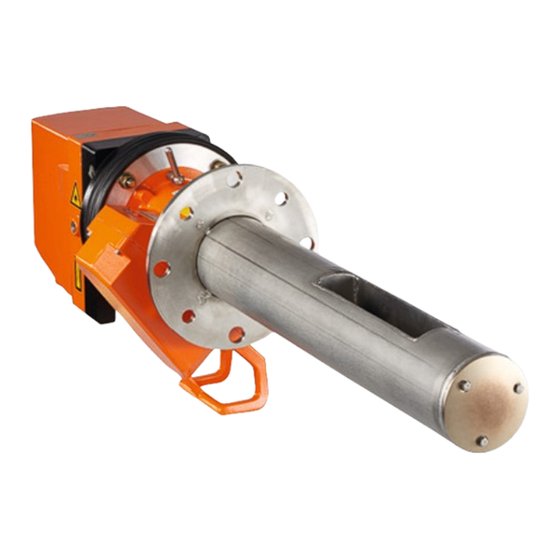
Tdls analyzer for nh3, hf or hci version with measuring probe
Hide thumbs
Also See for GM700:
- Operating instructions manual (112 pages) ,
- Addendum to operating instructions (14 pages) ,
- Operating instructions manual (100 pages)

Related Manuals for SICK GM700


Summary of Contents for SICK GM700
- Page 1 MMMOPERATING INSTRUCTIONS MMMI O P E R A T I N G I N S T R U C T I O N S GM700 TDLS Analyzer for NH3, HF or HCI Version with Measuring Probe Installation, Operation, Maintenance...
- Page 2 Subject to change without notice. © SICK AG. All rights reserved. O P E R A T I N G I N S T R U C T I O N S | GM700 8010100/YK22/V4-0/2015-12 | SICK Subject to change without notice...
- Page 3 Nice to know Supplementary information Link to information at another place 8010100/YK22/V4-0/2015-12 | SICK O P E R A T I N G I N S T R U C T I O N S | GM700 Subject to change without notice...
- Page 4 O P E R A T I N G I N S T R U C T I O N S | GM700 8010100/YK22/V4-0/2015-12 | SICK Subject to change without notice...
-
Page 5: Table Of Contents
Checking the scope of delivery ............34 4.1.2 Installation prerequisites..............34 8010100/YK22/V4-0/2015-12 | SICK O P E R A T I N G I N S T R U C T I O N S | GM700 Subject to change without notice... - Page 6 Cleaning the front window on the SR-unit ........61 Evaluation unit (EvU) ..................62 O P E R A T I N G I N S T R U C T I O N S | GM700 8010100/YK22/V4-0/2015-12 | SICK...
- Page 7 10.2 Positioning the probe reflector when the probe must be realigned ...99 8010100/YK22/V4-0/2015-12 | SICK O P E R A T I N G I N S T R U C T I O N S | GM700 Subject to change without notice...
-
Page 8: Safety Information
Ensure the protective grounding of the equipment and/or lines involved during installation and maintenance work in accordance with EN 61010-1. O P E R A T I N G I N S T R U C T I O N S | GM700 8010100/YK22/V4-0/2015-12 | SICK... -
Page 9: Protection Against Hazards Through Gases
Regularly check the functionality of the reverse flow safeguard. 8010100/YK22/V4-0/2015-12 | SICK O P E R A T I N G I N S T R U C T I O N S | GM700 Subject to change without notice... -
Page 10: Protection Against Laser Radiation
Laser warning sign Fig. 2: Laser sign for NH measurement O P E R A T I N G I N S T R U C T I O N S | GM700 8010100/YK22/V4-0/2015-12 | SICK Subject to change without notice... - Page 11 “Laser sign for HCI measurement”, page The emitted radiation is harmless to human skin. 8010100/YK22/V4-0/2015-12 | SICK O P E R A T I N G I N S T R U C T I O N S | GM700 Subject to change without notice...
-
Page 12: Behavior During Purge Air Failure
Keep these Operating Instructions available for reference. ▸ Pass on to a new owner/operator. O P E R A T I N G I N S T R U C T I O N S | GM700 8010100/YK22/V4-0/2015-12 | SICK Subject to change without notice... -
Page 13: Disposing Of Device Parts Harmful To The Environment
HCl or HF. Therefore, do not simply destroy the cuvette. 8010100/YK22/V4-0/2015-12 | SICK O P E R A T I N G I N S T R U C T I O N S | GM700 Subject to change without notice... -
Page 14: Product Overview
Measuring component: GM700-2 GM700-3 GM700-5 GM700-8 HCI / H GM700-9 O P E R A T I N G I N S T R U C T I O N S | GM700 8010100/YK22/V4-0/2015-12 | SICK Subject to change without notice... -
Page 15: Gm700 System, Measuring Probe Version, Layout
Ref. conditions Malfunction Hum: wet diag maint Inputs/outputs, analog, binary 8010100/YK22/V4-0/2015-12 | SICK O P E R A T I N G I N S T R U C T I O N S | GM700 Subject to change without notice... - Page 16 [1] One length included in scope of delivery [2] Included in scope of delivery O P E R A T I N G I N S T R U C T I O N S | GM700 8010100/YK22/V4-0/2015-12 | SICK...
-
Page 17: Measuring Probe In Detail
Part 75 can be carried out with the device fitted as far as usable for the application. 8010100/YK22/V4-0/2015-12 | SICK O P E R A T I N G I N S T R U C T I O N S | GM700 Subject to change without notice... -
Page 18: Gmp Probe With Open Measuring Gap
Purge air outlet Lever and locking device: Open O P E R A T I N G I N S T R U C T I O N S | GM700 8010100/YK22/V4-0/2015-12 | SICK Subject to change without notice... -
Page 19: Gpp Gas Diffusion Probe In Dry Or Wet Version
EPA Guideline CFR 40, Part 60 or Part 75 can be carried out are located on the enclosure as shown. 8010100/YK22/V4-0/2015-12 | SICK O P E R A T I N G I N S T R U C T I O N S | GM700 Subject to change without notice... -
Page 20: Gm700 Measuring Probes In Comparison
“Dimensions of weatherproof cover for GM700 SR-unit”, page 89. O P E R A T I N G I N S T R U C T I O N S | GM700 8010100/YK22/V4-0/2015-12 | SICK Subject to change without notice... -
Page 21: Measuring Principle
The differential absorption measurement also eliminate dust influences. 8010100/YK22/V4-0/2015-12 | SICK O P E R A T I N G I N S T R U C T I O N S | GM700 Subject to change without notice... -
Page 22: Project Planning Information
“Dimension drawing”, page 85 and following. O P E R A T I N G I N S T R U C T I O N S | GM700 8010100/YK22/V4-0/2015-12 | SICK Subject to change without notice... - Page 23 GM700 probe system”, page Table 3: Project Planning Checklist 8010100/YK22/V4-0/2015-12 | SICK O P E R A T I N G I N S T R U C T I O N S | GM700 Subject to change without notice...
- Page 24 Applicable (national) regulations on accident prevention must be observed. Table 3: Project Planning Checklist O P E R A T I N G I N S T R U C T I O N S | GM700 8010100/YK22/V4-0/2015-12 | SICK...
-
Page 25: Initial Onsite Installation
DIN 174 Platform 50 mm protrusion for circular duct cross-section 8010100/YK22/V4-0/2015-12 | SICK O P E R A T I N G I N S T R U C T I O N S | GM700 Subject to change without notice... -
Page 26: Uncovering The Duct
Due to the weight of the sender/receiver unit, we recommend reinforcing the flange tube fixture onsite with junction plates. O P E R A T I N G I N S T R U C T I O N S | GM700 8010100/YK22/V4-0/2015-12 | SICK... -
Page 27: Installing The Flange With Tube
Weld the flange tube on. 8010100/YK22/V4-0/2015-12 | SICK O P E R A T I N G I N S T R U C T I O N S | GM700 Subject to change without notice... -
Page 28: Installation Preparation For The Purge Air Unit (For Gmp Probe)
▸ Drill suitable openings as installation points as required. O P E R A T I N G I N S T R U C T I O N S | GM700 8010100/YK22/V4-0/2015-12 | SICK Subject to change without notice... -
Page 29: Preparations For Electrical Installation
The power connection must be made via a circuit-breaker switch. ● The grounding cable must be connected. ● 8010100/YK22/V4-0/2015-12 | SICK O P E R A T I N G I N S T R U C T I O N S | GM700 Subject to change without notice... - Page 30 3 analog inputs 6 x 0.5 mm connector(s) 3 analog outputs 6 x 0.5 mm O P E R A T I N G I N S T R U C T I O N S | GM700 8010100/YK22/V4-0/2015-12 | SICK Subject to change without notice...
-
Page 31: Can Bus Wiring
Status and signal cables from the EvU to the connection terminals of the customer's status/message devices can be added later as required. 8010100/YK22/V4-0/2015-12 | SICK O P E R A T I N G I N S T R U C T I O N S | GM700 Subject to change without notice... -
Page 32: Installation
O P E R A T I N G I N S T R U C T I O N S | GM700 8010100/YK22/V4-0/2015-12 | SICK... -
Page 33: Fitting System Components
Fig. 12: Fitting the terminal box with power supply unit Mounting holes 8010100/YK22/V4-0/2015-12 | SICK O P E R A T I N G I N S T R U C T I O N S | GM700 Subject to change without notice... -
Page 34: Installing The Evaluation Unit
4 mounting holes ∅ 8 mm Mounting surface Fastening brackets O P E R A T I N G I N S T R U C T I O N S | GM700 8010100/YK22/V4-0/2015-12 | SICK Subject to change without notice... -
Page 35: Installing The Evaluation Unit - Cast-Metal Enclosure Version
Fig. 15: Fitting the evaluation unit (cast enclosure) ▸ Close and lock the cover again. 8010100/YK22/V4-0/2015-12 | SICK O P E R A T I N G I N S T R U C T I O N S | GM700 Subject to change without notice... -
Page 36: Electrical Connection Of System Components
Information on selecting a suitable type of wiring can be found under “Circuit diagram (probe version)”, page O P E R A T I N G I N S T R U C T I O N S | GM700 8010100/YK22/V4-0/2015-12 | SICK Subject to change without notice... - Page 37 CAN-H and CAN-L. Connect the respective signals in the EvU and terminal box. 8010100/YK22/V4-0/2015-12 | SICK O P E R A T I N G I N S T R U C T I O N S | GM700 Subject to change without notice...
-
Page 38: Electrical Connection In The Evaluation Unit Evu
The power connection must be made via a circuit-breaker switch. ● The grounding cable must be connected. ● O P E R A T I N G I N S T R U C T I O N S | GM700 8010100/YK22/V4-0/2015-12 | SICK Subject to change without notice... - Page 39 The temperature on the cable glands can be >60 °C. 8010100/YK22/V4-0/2015-12 | SICK O P E R A T I N G I N S T R U C T I O N S | GM700 Subject to change without notice...
-
Page 40: Handling The Evaluation Unit
Displays all current measured values (temperature values resp, gas mode concentration); Displays computed values O P E R A T I N G I N S T R U C T I O N S | GM700 8010100/YK22/V4-0/2015-12 | SICK Subject to change without notice... -
Page 41: Menu Overview
600 ... 15000 hPa ● Table 4: GM700 menu overview 8010100/YK22/V4-0/2015-12 | SICK O P E R A T I N G I N S T R U C T I O N S | GM700 Subject to change without notice... - Page 42 ● XXXXXXX XXXX ● Table 4: GM700 menu overview O P E R A T I N G I N S T R U C T I O N S | GM700 8010100/YK22/V4-0/2015-12 | SICK Subject to change without notice...
- Page 43 All settings are overwritten! Table 4: GM700 menu overview 8010100/YK22/V4-0/2015-12 | SICK O P E R A T I N G I N S T R U C T I O N S | GM700 Subject to change without notice...
-
Page 44: Start-Up
Purge air supply, when fitted, must be ready for use. ● O P E R A T I N G I N S T R U C T I O N S | GM700 8010100/YK22/V4-0/2015-12 | SICK Subject to change without notice... -
Page 45: Mechanical Preparation
(see Fig.). Keep the transport safety devices as required. 8010100/YK22/V4-0/2015-12 | SICK O P E R A T I N G I N S T R U C T I O N S | GM700 Subject to change without notice... -
Page 46: Fitting The Sr-Unit On The Measuring Probe
Page O P E R A T I N G I N S T R U C T I O N S | GM700 8010100/YK22/V4-0/2015-12 | SICK Subject to change without notice... -
Page 47: Electrical Connections On The Sender/Receiver Unit
(via terminal box when necessary) Connection CAN cable (SR-unit and probe) 8010100/YK22/V4-0/2015-12 | SICK O P E R A T I N G I N S T R U C T I O N S | GM700 Subject to change without notice... -
Page 48: Optical Alignment
Only adjust the screws as shown in “Using the alignment tool”, page O P E R A T I N G I N S T R U C T I O N S | GM700 8010100/YK22/V4-0/2015-12 | SICK Subject to change without notice... -
Page 49: Optical Alignment Of Device Version For Hcl Measurement
P, m xxx.x brightness. back Align the sender/receiver unit 8010100/YK22/V4-0/2015-12 | SICK O P E R A T I N G I N S T R U C T I O N S | GM700 Subject to change without notice... -
Page 50: Zero Adjust
[1] ISO8573 Class 2 for particle size, amount of contaminator and oil, H O dew point O P E R A T I N G I N S T R U C T I O N S | GM700 8010100/YK22/V4-0/2015-12 | SICK... - Page 51 100°C, but may not exceed 120 °C on the probe connection. 8010100/YK22/V4-0/2015-12 | SICK O P E R A T I N G I N S T R U C T I O N S | GM700 Subject to change without notice...
-
Page 52: Fitting The Weatherproof Cover For The Sr-Unit
Pull the installation plate upwards and remove it from the cover. Installing the cover O P E R A T I N G I N S T R U C T I O N S | GM700 8010100/YK22/V4-0/2015-12 | SICK... - Page 53 “Weatherproof cover for the GM700 SR-unit”, page ▸ Fasten bottom mounting ring (3) again. 8010100/YK22/V4-0/2015-12 | SICK O P E R A T I N G I N S T R U C T I O N S | GM700 Subject to change without notice...
-
Page 54: Evaluation Unit Start-Up
“Handling the Evaluation Unit”, page O P E R A T I N G I N S T R U C T I O N S | GM700 8010100/YK22/V4-0/2015-12 | SICK Subject to change without notice... -
Page 55: Operating States
Supply line " with cutting-clamping ring connection (Swagelok) ● 8010100/YK22/V4-0/2015-12 | SICK O P E R A T I N G I N S T R U C T I O N S | GM700 Subject to change without notice... -
Page 56: Starting Operating Mode
Set parameters, special times and measuring range, “Handling the Evaluation Unit”, page 42. O P E R A T I N G I N S T R U C T I O N S | GM700 8010100/YK22/V4-0/2015-12 | SICK Subject to change without notice... - Page 57 Confirm the prompt. Zero point adjustment runs and Zero Measuring is displayed. 8010100/YK22/V4-0/2015-12 | SICK O P E R A T I N G I N S T R U C T I O N S | GM700 Subject to change without notice...
-
Page 58: Maintenance
Maintenance tasks for purge air unit→ Purge air unit Operating Instructions. O P E R A T I N G I N S T R U C T I O N S | GM700 8010100/YK22/V4-0/2015-12 | SICK... -
Page 59: Maintenance Work On Sr-Unit
Close and lock the enclosure again to protect the cleaned optical interface against humidity or dust. 8010100/YK22/V4-0/2015-12 | SICK O P E R A T I N G I N S T R U C T I O N S | GM700 Subject to change without notice... -
Page 60: Evaluation Unit (Evu)
▸ Contact SICK Service or the local sales representative. O P E R A T I N G I N S T R U C T I O N S | GM700 8010100/YK22/V4-0/2015-12 | SICK Subject to change without notice... -
Page 61: Controlling And Tracking The Laser Working Point During Measurement
Filter box with adapter plate for the GM700 ● 8010100/YK22/V4-0/2015-12 | SICK O P E R A T I N G I N S T R U C T I O N S | GM700 Subject to change without notice... - Page 62 Reflector enclosure Measured values are displayed on the EvU in mg/m3 • m (operation). O P E R A T I N G I N S T R U C T I O N S | GM700 8010100/YK22/V4-0/2015-12 | SICK...
-
Page 63: Determining The Necessary Test Gas Concentration
Store safely until filter box measurement is completed. 8010100/YK22/V4-0/2015-12 | SICK O P E R A T I N G I N S T R U C T I O N S | GM700 Subject to change without notice... -
Page 64: Carry Out Filter Box Measurement
▸ Switch all chamber valves to “Zero gas” and the Measure/Purge valve to “Purge”. O P E R A T I N G I N S T R U C T I O N S | GM700 8010100/YK22/V4-0/2015-12 | SICK... - Page 65 Refit the SR-unit back onto the sampling point in the correct position. 8010100/YK22/V4-0/2015-12 | SICK O P E R A T I N G I N S T R U C T I O N S | GM700 Subject to change without notice...
-
Page 66: Checking The Gas Analyzer With Test Cell Gmk10
Length of hose for safe discharge of the test gas ● Measurement of ambient air pressure ● O P E R A T I N G I N S T R U C T I O N S | GM700 8010100/YK22/V4-0/2015-12 | SICK Subject to change without notice... -
Page 67: Installation Of The Gm700 Components With The Test Cell Gmk10
Fig. 39: Connections of the GMK10 test cell Power supply Sample gas connection Gas outlet 8010100/YK22/V4-0/2015-12 | SICK O P E R A T I N G I N S T R U C T I O N S | GM700 Subject to change without notice... -
Page 68: Carrying Out Measurement
If required, see separate Operating Instructions of the temperature controller. O P E R A T I N G I N S T R U C T I O N S | GM700 8010100/YK22/V4-0/2015-12 | SICK Subject to change without notice... - Page 69 (during operation, relative to 1 m active measuring path). 8010100/YK22/V4-0/2015-12 | SICK O P E R A T I N G I N S T R U C T I O N S | GM700 Subject to change without notice...
- Page 70 Before switching off the heaters, the system must be purged with dry nitrogen for a minimum of 5 minutes. Make gas connections. O P E R A T I N G I N S T R U C T I O N S | GM700 8010100/YK22/V4-0/2015-12 | SICK Subject to change without notice...
-
Page 71: Troubleshooting And Clearing Malfunctions
8010100/YK22/V4-0/2015-12 | SICK O P E R A T I N G I N S T R U C T I O N S | GM700 Subject to change without notice... -
Page 72: Display And Retrieval Of Messages On The Evaluation Unit
– Check and clear the specified malfunction. Group malfunction Table 11: Troubleshooting Table O P E R A T I N G I N S T R U C T I O N S | GM700 8010100/YK22/V4-0/2015-12 | SICK Subject to change without notice... -
Page 73: Troubleshooting And Clearing Malfunctions, Evaluation Unit
SR-unit Table 12: Troubleshooting and clearing malfunctions, evaluation unit 8010100/YK22/V4-0/2015-12 | SICK O P E R A T I N G I N S T R U C T I O N S | GM700 Subject to change without notice... -
Page 74: Error Messages
If not successful, contact Service Table 13: Error messages O P E R A T I N G I N S T R U C T I O N S | GM700 8010100/YK22/V4-0/2015-12 | SICK Subject to change without notice... - Page 75 “Optical alignment”, page 50. inaccurate Table 13: Error messages 8010100/YK22/V4-0/2015-12 | SICK O P E R A T I N G I N S T R U C T I O N S | GM700 Subject to change without notice...
-
Page 76: Warning Messages
Ambient temperature too high ● Table 14: Warning messages O P E R A T I N G I N S T R U C T I O N S | GM700 8010100/YK22/V4-0/2015-12 | SICK Subject to change without notice... -
Page 77: Further Tips On Troubleshooting
Outer plug-in connectors on SR-unit. ▸ Inner plug-in connectors in SR-unit. 8010100/YK22/V4-0/2015-12 | SICK O P E R A T I N G I N S T R U C T I O N S | GM700 Subject to change without notice... -
Page 78: Technical Data, Expendable And Spare Parts
≤ 85% relative humidity; non-condensing Table 15: Technical data GM700 system O P E R A T I N G I N S T R U C T I O N S | GM700 8010100/YK22/V4-0/2015-12 | SICK Subject to change without notice... - Page 79 45 kg Table 18: Technical data GPP measuring probe 8010100/YK22/V4-0/2015-12 | SICK O P E R A T I N G I N S T R U C T I O N S | GM700 Subject to change without notice...
- Page 80 Electrically isolated Table 20: Technical data GM700 evaluation unit: Cast metal enclosure O P E R A T I N G I N S T R U C T I O N S | GM700 8010100/YK22/V4-0/2015-12 | SICK Subject to change without notice...
- Page 81 Temperature sensor PT1000 Table 22: Technical data purge air fixture 8010100/YK22/V4-0/2015-12 | SICK O P E R A T I N G I N S T R U C T I O N S | GM700 Subject to change without notice...
- Page 82 1376 V AC Table 23: Characteristic data for electric isolation O P E R A T I N G I N S T R U C T I O N S | GM700 8010100/YK22/V4-0/2015-12 | SICK Subject to change without notice...
-
Page 83: Dimension Drawing
Dimension drawing sender/receiver unit GM700 (dimensions in mm) 90° 8010100/YK22/V4-0/2015-12 | SICK O P E R A T I N G I N S T R U C T I O N S | GM700 Subject to change without notice... -
Page 84: Dimensions Of Open Measuring Probe - Gmp
2628 1988 1738 1488 1238 Application-specific lengths on request O P E R A T I N G I N S T R U C T I O N S | GM700 8010100/YK22/V4-0/2015-12 | SICK Subject to change without notice... -
Page 85: Dimensions Of Gpp Measuring Probes
2598 2047 1797 1547 1297 Application-specific lengths on request 8010100/YK22/V4-0/2015-12 | SICK O P E R A T I N G I N S T R U C T I O N S | GM700 Subject to change without notice... -
Page 86: Dimension Drawing Evaluation Unit Gm700: Sheet Steel Enclosure (Dimensions In Mm)
9.2.6 Connection unit GM700 (Can bus option) (dimensions in mm) O P E R A T I N G I N S T R U C T I O N S | GM700 8010100/YK22/V4-0/2015-12 | SICK Subject to change without notice... -
Page 87: Dimensions Of Weatherproof Cover For Gm700 Sr-Unit
Alternatively, an ANSI flange provided by the customer can be used. 8010100/YK22/V4-0/2015-12 | SICK O P E R A T I N G I N S T R U C T I O N S | GM700 Subject to change without notice... -
Page 88: Accessories, Expendable And Spare Parts
Spare parts set, heating, front window, GPP Table 26: Spare parts for the measuring probe O P E R A T I N G I N S T R U C T I O N S | GM700 8010100/YK22/V4-0/2015-12 | SICK... - Page 89 Pressure compensation element Table 26: Spare parts for the measuring probe 8010100/YK22/V4-0/2015-12 | SICK O P E R A T I N G I N S T R U C T I O N S | GM700 Subject to change without notice...
-
Page 90: Spare Parts For The Evaluation Unit
Sealing tape Table 29: Fixing accessories for the SR unit - measuring probe O P E R A T I N G I N S T R U C T I O N S | GM700 8010100/YK22/V4-0/2015-12 | SICK Subject to change without notice... -
Page 91: Spare Parts Assignment For Sender/Receiver Unit
Detector module mea- surement Heater Heater Optics body 8010100/YK22/V4-0/2015-12 | SICK O P E R A T I N G I N S T R U C T I O N S | GM700 Subject to change without notice... - Page 92 Fixing set, flange Clamping ring bolt Lever for alignment tool O P E R A T I N G I N S T R U C T I O N S | GM700 8010100/YK22/V4-0/2015-12 | SICK Subject to change without notice...
- Page 93 Fig. 45: Spare parts assignment GPP probe: Flange part 8010100/YK22/V4-0/2015-12 | SICK O P E R A T I N G I N S T R U C T I O N S | GM700 Subject to change without notice...
- Page 94 4 049 466 Fig. 47: Spare parts assignment GPP probe: Window O P E R A T I N G I N S T R U C T I O N S | GM700 8010100/YK22/V4-0/2015-12 | SICK Subject to change without notice...
-
Page 95: Annex
1.6 above the limit value of the European health and safety regulations for artificial optical radiation or EN 60825-1:2007. 8010100/YK22/V4-0/2015-12 | SICK O P E R A T I N G I N S T R U C T I O N S | GM700 Subject to change without notice... - Page 96 (<0°C). Table 31: Power output of the GM700 in planned operating state O P E R A T I N G I N S T R U C T I O N S | GM700 8010100/YK22/V4-0/2015-12 | SICK...
-
Page 97: Positioning The Probe Reflector When The Probe Must Be Realigned
30° to the right and pull the reflector unit out. 8010100/YK22/V4-0/2015-12 | SICK O P E R A T I N G I N S T R U C T I O N S | GM700 Subject to change without notice... - Page 98 The socket screw shows the position of the hollow triple. It must always point towards the connector on the SR-unit so that the alignment is correct. O P E R A T I N G I N S T R U C T I O N S | GM700 8010100/YK22/V4-0/2015-12 | SICK...
- Page 99 Fig. 51: Positioning of probe reflector with probe aligned Socket screw hidden 8010100/YK22/V4-0/2015-12 | SICK O P E R A T I N G I N S T R U C T I O N S | GM700 Subject to change without notice...
- Page 100 - Operating mode ................43 - Password ..................43 O P E R A T I N G I N S T R U C T I O N S | GM700 8010100/YK22/V4-0/2015-12 | SICK Subject to change without notice...
- Page 101 INDEX 8010100/YK22/V4-0/2015-12 | SICK O P E R A T I N G I N S T R U C T I O N S | GM700 Subject to change without notice...
- Page 102 E-Mail sales@sick.co.nz United Arab Emirates China Norway E-Mail sick@sick.no USA/Mexico Denmark Poland E-Mail sick@sick.dk Finland Romania Vietnam France Russia Gemany Singapore Great Britain Slovakia E-Mail mail@sick-sk.sk Hong Kong Slovenia Hungary South Africa www.sick.com SICK AG | Waldkirch | Germany | www.sick.com...
Need help?
Do you have a question about the GM700 and is the answer not in the manual?
Questions and answers