SICK GM32 Technical Information
In-situ gas analyzer measuring probe version
Hide thumbs
Also See for GM32:
- Operating instructions manual (76 pages) ,
- Operating instructions manual (81 pages) ,
- Operating instructions manual (80 pages)
Table of Contents
Advertisement
Quick Links
Advertisement
Table of Contents

Related Manuals for SICK GM32


Summary of Contents for SICK GM32
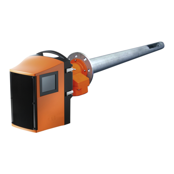
- Page 1 Title Page TE C H N I C A L I N F O R M A T I O N GM32 In-situ Gas Analyzer Measuring Probe Version Operating for Service Technicians Technical Details These Instructions are intended exclusively for trained personnel.
- Page 2 SICK AG assumes no liability for the correctness of an unauthorized translation. Contact SICK AG or your local representative in case of doubt. Legal Information Subject to change without notice. © SICK AG. All rights reserved. GM32 · Technical information · 8011923 · V 1.4 · © SICK AG...
- Page 3 Risk or hazardous situation which could result in severe personal injury or death. CAUTION Hazard or unsafe practice which could result in personal injury or property damage. NOTICE Hazard which could result in material damage. GM32 · Technical information · 8011923 · V 1.4 · © SICK AG...
-
Page 4: Table Of Contents
Measuring probe in detail ........... . 17 GM32 · Technical information · 8011923 · V 1.4 · © SICK AG... - Page 5 SCU connection (overview) ........... 23 Connecting the GM32 to the CAN bus and to the SCU ......24 3.3.1...
- Page 6 Setting the GM32 analyzer/SCU IP address ....... . . 59...
-
Page 7: General Information
General Information GM32 General Information Responsibility of user GM32 · Technical information · 8011923 · V 1.4 · © SICK AG... -
Page 8: Responsibility Of User
Designated users 1.1.1 This Technical Information is aimed at qualified persons familiar with the GM32 and who, based on their device-specific training and knowledge of the device as well as knowledge of the relevant regulations, can assess the tasks given and recognize the dangers involved. -
Page 9: Product Description (Details)
Product Description (Details) GM32 Product Description (Details) Functional principle Check cycles Remote operation GM32 · Technical information · 8011923 · V 1.4 · © SICK AG... -
Page 10: Measuring Method
(filter) through which the gas mixture being measured flows - the active measuring path. The GM32 SR-unit determines the concentration of the respective gases based on wave- length-specific light absorption by the gas mixture in the active measuring path. -
Page 11: Signal Evaluation
To do this, the respective evaluation IR range for the components to be measured is defined so that no “foreign gases” disturb the spectrum structure. GM32 · Technical information · 8011923 · V 1.4 · © SICK AG... -
Page 12: Zero Adjust (Description)
Relative to the double beam path used in measuring operation, this gives a C x L of approx. 500 ppm x m or 600 mg/m³ x m 1 zero point reflector ● GM32 · Technical information · 8011923 · V 1.4 · © SICK AG... -
Page 13: Check Cycle (Function)
Wavelength scale monitoring 2.5.2.1 The grating spectrometer used in the GM32 shows, due to the design, wavelength scale drifts caused by mechanical effects (e.g. length changes caused by temperature fluctua- tions). Compensation is realized through continuous determination of this drift during measuring operation and calculation back to the original state through numeric interpola- tion. -
Page 14: Determining The Zero And Reference Point
Determining a value for an NO absorption line serves to monitor the cell concentration. A maintenance request is signaled when the value sinks below 0.1 absorption units. GM32 · Technical information · 8011923 · V 1.4 · © SICK AG... -
Page 15: Summary
90 s. The Not_measuring signal is not active during the output. As an alternative, the zero and reference values of the last check cycle can be read out using SOPAS ET menu /Diagnosis/Check cycle. GM32 · Technical information · 8011923 · V 1.4 · © SICK AG... -
Page 16: Contamination Compensation
This can be caused, for example, when the probe bends due to varying gas tempera- tures. These swivel movements are compensated continually on the GM32 by the built-in tracking mirror. Motors tilt this mirror in two directions and can thereby compensate occurring swivel movements. -
Page 17: Measuring Probe In Detail
When using a GPP probe/EPA probe, an audit measurement conforming to EPA CFR 40 Part 60 and/or Part 75 can be carried out with the device fitted. GM32 · Technical information · 8011923 · V 1.4 · © SICK AG... - Page 18 Fig. 4 GMP measuring probe (with open measuring gap) Lever position Temperature sensor PT 1000 Open measuring path (measuring gap) Purge air outlet Lever and locking device: Open GM32 · Technical information · 8011923 · V 1.4 · © SICK AG...
- Page 19 CAN bus and power supply as well as the test gas connection and pressure measurement connection are fitted on this housing and serve manual activation of the audit measurement according to EPA Guideline CFR 40, Part 60 or Part 75. GM32 · Technical information · 8011923 · V 1.4 · © SICK AG...
- Page 20 Product Description (Details) GM32 · Technical information · 8011923 · V 1.4 · © SICK AG...
-
Page 21: Can Connection
CAN Connection GM32 CAN Connection CAN connection SCU connection GM32 · Technical information · 8011923 · V 1.4 · © SICK AG... -
Page 22: Gm32 Can Connection
Activating or deactivating terminating resistors Operating Instructions of bus partici- pants. For GM32: p. 24, §3.3 and Operating Instructions “Modular System I/O”. Stub lines lead to reflections on the bus, therefore: Avoid stub lines whenever possible, otherwise limit these to max. 10 m. -
Page 23: Scu Connection (Overview)
CAN Connection SCU connection (overview) 3 . 2 As an option, the GM32 (and further analyzers) can be operated using an SCU (System Control Unit). The SCU is an operating unit for comfortable, powerful analyzer control. The following actions can be performed on the analyzers via the SCU: Control, parameter setting and display. -
Page 24: Connecting The Gm32 To The Can Bus And To The Scu
CAN Connection Connecting the GM32 to the CAN bus and to the SCU 3. 3 Connection of the GM32 to the CAN bus, here as example to the SCU. Fig. 8 Example: CAN connection of the SCU to the GM32... -
Page 25: Settings In Gm32
Settings in the SCU 3.3.2 Set in the SCU ( Operating Instructions of the SCU): ● – Baudrate: Corresponding to the GM32 setting – CAN: 1 (always) GM32 · Technical information · 8011923 · V 1.4 · © SICK AG... -
Page 26: Mapping Table
= zero from MV14 Monitor value 28 = range from MV14 Help values from SCU to GM32 - Help value (HV) Index Reference value HV01 Temperature [K] HV02 Pressure [hPa] GM32 · Technical information · 8011923 · V 1.4 · © SICK AG... - Page 27 U01..U08 Uncertain C01..C08 Check E01..E16 Extended Status of measured values (MV) Index Diagnostic message MVxxF01..F64 Failure MVxxM01..M08 Maintenance MVxxU01..U16 Uncertain MVxxC01..C08 Check MVxxE01..E32 Extended xx = 1..16 GM32 · Technical information · 8011923 · V 1.4 · © SICK AG...
- Page 28 CAN Connection GM32 · Technical information · 8011923 · V 1.4 · © SICK AG...
-
Page 29: Operation (Specialist Menus)
Operation (Specialist Menus) GM32 Operation (Specialist Menus) SOPAS ET Menus GM32 · Technical information · 8011923 · V 1.4 · © SICK AG... -
Page 30: Sopas Et (Description)
Operator menus and measured value displays are also available on an external PC via Eth- ernet for user comfort (with the engineering tool SOPAS ET). The SICK Open Portal for Applications and Systems (SOPAS) is an engineering tool for com- munication with analyzers and sensors. -
Page 31: Menu Tree (In Sopas Et)
p. 47, §4.2.5.4 ¦ Sensor values A = user level “Authorized user”. S = user level “Service”. Not described in this Manual. Please contact SICK Customer Service. GM32 · Technical information · 8011923 · V 1.4 · © SICK AG... -
Page 32: Changing The User Level
The menu tree shown above is the structure for user level “Authorized user” and “Service”. Enter a password for the corresponding user level: User level Password Authorized client HIDE Service GM32SERVICE Upper case mandatory GM32 · Technical information · 8011923 · V 1.4 · © SICK AG... -
Page 33: Measured Values
The measured value display can be configured. It is defined by the assignment of ana- log inputs. Operating mode of the analyzer ● Operating mode of the components ● Current sample gas pressure ● Current sample gas temperature ● GM32 · Technical information · 8011923 · V 1.4 · © SICK AG... -
Page 34: Parameters
Default 60 min. (change only possible for user level “Service”). Check cycle interval: Interval for the check cycle. ● 0 min. means: Switched off (change only possible for user level “Service”). GM32 · Technical information · 8011923 · V 1.4 · © SICK AG... -
Page 35: Spectrometer
Spectrometer 4.2.3.2 Menu: GM32/Parameter/Spectrometer Internal parameters of the spectrometer (change only possible with user level ● “Service”). Coefficients 4.2.3.3 Menu: GM32/Parameter/Coefficients Polynomial to adapt measured values. ● GM32 · Technical information · 8011923 · V 1.4 · © SICK AG... -
Page 36: Coefficients Boxmeasuring
Polynomial to adapt measured values to the filter box (change only possible with user ● level “Service”). Adjustment sensor 4.2.3.5 Menu: GM32/Parameter/Adjustment sensor Internal parameters of sensor alignment (change only possible with user level ● “Service”). GM32 · Technical information · 8011923 · V 1.4 · © SICK AG... -
Page 37: Logbook
- Ring buffer mode - The oldest entries are overwritten with the current entries. No relevant message is displayed. Number of logbook Number of logbook entries messages GM32 · Technical information · 8011923 · V 1.4 · © SICK AG... -
Page 38: Analog Outputs
Physical unit of the measured variable ● Electrical zero point “Live Zero”: 0 or 4 mA ● Analog input range for signal source: Start / End ● GM32 · Technical information · 8011923 · V 1.4 · © SICK AG... -
Page 39: Digital Inputs
A maintenance request is available Uncertain The GM32 is in an indefinite state Not_measuring Zero adjust is running Check cycle is running Operating mode ’’Maintenance’’ Operating mode ’’Boxmeasuring’’ (filter box measurement) GM32 · Technical information · 8011923 · V 1.4 · © SICK AG... - Page 40 A message is available Output_control_values Outputs control values Measuring_range Outside measuring range Purge air failure Error in purge air supply No_function No function assigned Inverted Inverts the signal GM32 · Technical information · 8011923 · V 1.4 · © SICK AG...
-
Page 41: Hardware Map
2 Use “Edit” to enter installed modules in the corresponding line. Example: The first module is an “AO02” module. 3 “Save”. 4 Store the modules with “Restart IOProxy”. GM32 · Technical information · 8011923 · V 1.4 · © SICK AG... -
Page 42: Adjustment
For further information on optical alignment GM32 Operating Instructions 1 “Start alignment” Measuring operation is suspended during alignment. Tolerances: X: ±0.05 Y: ±0.05 2 Click “Measuring” after completing alignment. GM32 · Technical information · 8011923 · V 1.4 · © SICK AG... -
Page 43: Zero Adjust (Service Level Only)
Zero adjust takes about 5 minutes. The GM32 switches to operating mode “Maintenance”. “Start measuring mode” automatically starts a reference cycle. The GM32 then switches to operating mode “Measuring”. GM32 · Technical information · 8011923 · V 1.4 · © SICK AG... -
Page 44: Boxmeasuring (Service Level Only)
Operation (Specialist Menus) Boxmeasuring (Service level only) 4.2.4.3 Menu: GM32/Adjustment/Boxmeasuring Boxmeasuring description p. 68, §5.2 GM32 · Technical information · 8011923 · V 1.4 · © SICK AG... -
Page 45: Diagnosis
Symbol crossed out: Uncompressed. Significance and default: p. 37, §4.2.3.6 Ring buffer mode Warning mode Significance and default: p. 37, §4.2.3.6 Entries Number of entries of selected filter. GM32 · Technical information · 8011923 · V 1.4 · © SICK AG... - Page 46 For “Uncompressed”: Clearing of message. For “Compressed”: Last clearing of message. Time Stop Format: hh:mm:ss For “Uncompressed”: Clearing of message. For “Compressed”: Last clearing of message. Only for compressed data storage GM32 · Technical information · 8011923 · V 1.4 · © SICK AG...
-
Page 47: Check Cycle
Span: Control point as physical and current value relative to the upper measuring range ● value Sensor values 4.2.5.4 Menu: GM32/Diagnosis/Sensor values Spectral analysis Menu: GM32/Diagnosis/Sensor values/Spectral evaluation Sources and values for spectral evaluation ● GM32 · Technical information · 8011923 · V 1.4 · © SICK AG... - Page 48 Offset: Offsets are determined during the check cycle or after amplifier switching. ● A .. D, Sum: Current signals. ● Counter: Delay time before correction made. ● GM32 · Technical information · 8011923 · V 1.4 · © SICK AG...
- Page 49 Mirror tracking Menu: GM32/Diagnosis/Sensor values/Alignment Current values from alignment. A device restart sets the number of movements to zero. Process optic Menu: GM32/Diagnosis/Sensor values/Process optic Current analyzer values GM32 · Technical information · 8011923 · V 1.4 · © SICK AG...
-
Page 50: Temperature Unit
Operation (Specialist Menus) Temperature unit 4.2.5.5 Menu: GM32/Diagnosis/Sensor values/Temperature unit Current analyzer values GM32 · Technical information · 8011923 · V 1.4 · © SICK AG... -
Page 51: Spectra
Maximum measurement reflector signal on the zero path: 45000 .. 50000 digits. ● Change with user level Service in menu Parameter Spectrometer Maximum lamp intensity. GM32 · Technical information · 8011923 · V 1.4 · © SICK AG... - Page 52 Change with user level Service in menu Parameter Spectrometer Maximum lamp ● intensity. Aperture signal (dark signal) Menu: GM32/Diagnosis/Sensor values/Spectra/Aperture signal Measurement on blanking diaphragm. Only updated during the check cycle. GM32 · Technical information · 8011923 · V 1.4 · © SICK AG...
- Page 53 Menu: GM32/Diagnosis/Sensor values/Spectra/Filtered absorption Averaged absorption spectrum. Preselected filter, e.g. IRR filter (infinite impulse response filter). Menu /Parameter/Spectral alignment serves to select the filter (only possible for user level “Service”). GM32 · Technical information · 8011923 · V 1.4 · © SICK AG...
- Page 54 This spectrum serves to calculate the absorption and shows the calculated spectrum on the measurement reflector on the smoke-free zero path. Reference spectrum = (zero point reflector signal - aperture signal (dark signal)) * scaling constant. GM32 · Technical information · 8011923 · V 1.4 · © SICK AG...
- Page 55 Operation (Specialist Menus) Normalisation Menu: GM32/Diagnosis/Sensor values/Spectra/Normalisation Graphic representation of normalisation (constants for zero adjust). Normalisation must be between 0.8 and 5. GM32 · Technical information · 8011923 · V 1.4 · © SICK AG...
-
Page 56: Maintenance
Starts a check cycle System reset Resets the system. Then reconnect SOPAS ET and GM32 again ( p. 30, §4.1). Lamp hour meter 4.2.6.2 Menu: GM32/Maintenance/Lamp hour meter GM32 · Technical information · 8011923 · V 1.4 · © SICK AG... -
Page 57: Save Eeprom
Goes on when the load process finishes. Start-up Assistant 4.2.7 Menu: GM32/Start-Up Assistant The Start-up Assistant guides you through commissioning step by step. Criterion: SOPAS ET as from Version 2.32 GM32 · Technical information · 8011923 · V 1.4 · © SICK AG... -
Page 58: Program/Data Structure ("Firmware", "Device Description File")
Program/data structure (“Firmware”, “Device description file”) 4. 3 To load data to the GM32 analyzer: The GM32 analyzer can be accessed using the SCU (i.e. connect the laptop to the SCU and not to the electronic unit). Login to SOPAS ET as “Service”. -
Page 59: Setting The Gm32 Analyzer/Scu Ip Address
8 After a new “Network scan”, the “Basic Sensor” reports under the set IP address. 9 Drag the “Basic Sensor” into the “Project tree”: This loads the “Basic Sensor” device description. 10 Load firmware ( p. 60, §4.3.3). GM32 · Technical information · 8011923 · V 1.4 · © SICK AG... -
Page 60: Updating The Firmware (Gm32 Analyzer/Scu)
First save the existing parameters ( p. 63, §4.3.5.2) and then load the firmware ( p. 63, §4.3.5.3). Parameters that no longer match are displayed. Auxiliary means required Firmware installation package with .smf file (there are two .smf files for GM32 analyzers) Firmware files have the suffix .smf ● Procedure 1 Connect the PC to the Ethernet interface of the GM32 or SCU. -
Page 61: Loading The Device Description File ("Make Available To Sopas Et")
4 “Module Manager” 5 “Install new or update existing module” 6 Follow the instructions. When the device description files are already available on the GM32 analyzer or SCU and SOPAS ET is to be made available again: 1 Call SOPAS ET. -
Page 62: Saving And Loading Parameters (Device Data)
“Immediate download” : Parameters are loaded continuously to the device. b) “Download on request”: Load parameters to the device: 1 “Communication” 2 “Switch offline” 3 “Download all parameters to device” 4 “Switch online” GM32 · Technical information · 8011923 · V 1.4 · © SICK AG... -
Page 63: Saving Parameters (Gm32 Analyzer/Scu) To An External Data Medium
Saving parameters (GM32 analyzer/SCU) to an external data medium 4.3.5.2 You can only reset the GM32 to the last usable state after data losses when you have previously saved the data on an external data medium (e.g. a PC). Parameter files have the suffix .sdv ●... - Page 64 Operation (Specialist Menus) GM32 · Technical information · 8011923 · V 1.4 · © SICK AG...
-
Page 65: Maintenance
Maintenance GM32 Maintenance Maintenance plan Maintenance work Preventative maintenance Recommended spare parts GM32 · Technical information · 8011923 · V 1.4 · © SICK AG... -
Page 66: Zero Adjust (Zero Point Check)
3 Put the GM32 in a safe place and put it into operation with the probe fitted. The probe must only be in inert gas (e.g. ambient air). - Page 67 When the value on the measurement reflector reaches a value between 45000 and 50000 digits, the GM32 can be compared against zero in the SOPAS ET menu Adjust- ment Zero adjust ( p. 43, §4.2.4.2). 14 Use menu Diagnosis Sensor values Spectra Absorption ( p. 53) to check the smoke-free spectrum.
-
Page 68: Boxmeasuring
The gas filter box serves to check the measuring channels with test gases. WARNING: Hazards through toxic or combustible gases. The user must be familiar with the hazards through toxic and combustible gases. GM32 · Technical information · 8011923 · V 1.4 · © SICK AG... -
Page 69: Preparing The Filter Box
Test gas valve to switch individual measuring chambers ON/OFF switch Pump ON/OFF switch Energy supply connection Temperature displays, preheater and measuring Recommendation: Use nitrogen (N ) as zero gas. GM32 · Technical information · 8011923 · V 1.4 · © SICK AG... - Page 70 – Measuring path <5m (R=-1982) – Measuring path >5m (R=-5000). 8 Fit the reflector on the filter box. 9 Fit the suitable GM32 adapter plate to the filter box GM32 · Technical information · 8011923 · V 1.4 · © SICK AG...
-
Page 71: Determining The Necessary Test Gas Concentration
(see Fig. above) Temperature set for the filter box in °C Conversion factor ppm to mg/Nm NO = 1.34; NO2 = 2.05; NH3 = 0.76; SO2 = 2.86 GM32 · Technical information · 8011923 · V 1.4 · © SICK AG... -
Page 72: Procedure
Provide an approx. 20 cm high support for the filter box. Fig. 14 GM32 with filter box 6 SOPAS ET menu Adjustment Boxmeasuring ( p. 44, §4.2.4.3) GM32 · Technical information · 8011923 · V 1.4 · © SICK AG... - Page 73 Status line on operator panel: “Boxmeasuring” ● Maintenance request (yellow LED) active ● 10 Wait (up to approx. 20 minutes) until the message “Boxmeasuring (fill in gas!)” appears in “Operating mode”. GM32 · Technical information · 8011923 · V 1.4 · © SICK AG...
- Page 74 12 SOPAS ET menu Diagnosis Sensor values Spectra Absorption ( p. 53). Measurement signal must be approximately at zero and be straight as average value. GM32 · Technical information · 8011923 · V 1.4 · © SICK AG...
- Page 75 Click “Measuring” to switch the GM32 to operating mode “Measuring”. The GM32 triggers a reference cycle. The check is completed with operating mode ’’Measuring’’. The filter box scaling is overwritten automatically. GM32 · Technical information · 8011923 · V 1.4 · © SICK AG...
-
Page 76: Test Gas Feeding (For Gpp Measuring Probe)
The zero or test gas concentration in the filter frit is measured and the GM32 adjusted accordingly. Fig. 16... -
Page 77: One-Off Initial Measurement - Determining The Test Gas Pressure
Supply line 1/4" with Swagelok fitting The GPP probe remains installed in the gas duct. 1 Switch the GM32 to Maintenance (on the operator panel or in SOPAS ET menu: GM32/ Maintenance/Operating mode switch p. 56, §4.2.6.1) 2 Connect N or instrument air to the probe via a pressure reducer (... -
Page 78: Manual Test Gas Feeding
Pressure gauge / pressure reducer Supply line 1/4" with Swagelok fitting 1 Switch the GM32 to Maintenance (on the operator panel or in SOPAS ET menu: GM32/ Maintenance/Operating mode switch p. 56, §4.2.6.1) 2 Connect the desired zero and/or test gas via pressure reducer to the probe ( p. 76, Fig. -
Page 79: Fitting And Removing The Power Supply Unit Of The Connection Unit
5 Push the power supply unit upwards and take out. 6 The power supply unit can be hung on the bracket of the SR-unit. Fig. 18 Power supply unit hung on Fit in the reverse sequence. GM32 · Technical information · 8011923 · V 1.4 · © SICK AG... - Page 80 Maintenance GM32 · Technical information · 8011923 · V 1.4 · © SICK AG...
-
Page 81: Shutting Down/Restarting
Shutting down/Restarting GM32 Shutting down/Restarting GM32 · Technical information · 8011923 · V 1.4 · © SICK AG... -
Page 82: Qualification Requirements
(when necessary) Stored transport safety devices and, when available, the original packaging of the mea- ● suring system Insulation material/close box to protect cables against atmospheric conditions ● GM32 · Technical information · 8011923 · V 1.4 · © SICK AG... -
Page 83: Shutdown
For GMP probe: Purge air fixture Seal “Flange with tube” For GPP probe: Flange attachment Lay the SR-unit with the fitted measuring probe on the floor and free from jolts. GM32 · Technical information · 8011923 · V 1.4 · © SICK AG... -
Page 84: Disconnecting The Purge Air Connection
The next tasks are to first put the purge air unit and further components - as far as applica- ble - out of operation. GM32 · Technical information · 8011923 · V 1.4 · © SICK AG... -
Page 85: Putting The Purge Air Unit Out Of Operation
If the existing measuring point is to used for the purge air unit again, e.g., for a different measuring system: Check the technical data or contact SICK to determine whether the purge air unit is suit- able for the planned application purpose. -
Page 86: Further Components On The Measuring Point
If the cables provided by the customer at the measuring point can be used for other purposes: Insulate all open cable ends. Protect the cable ends against atmospheric conditions, e.g., with a close box to prevent corrosion and contamination. GM32 · Technical information · 8011923 · V 1.4 · © SICK AG... -
Page 87: Conservation Measures, Correct Storage And Transport
Conservation measures, correct storage and transport 6 . 4 This Section describes how to prepare the GM32 for storage for later use or transport. Clean the outside of the closed SR-unit housing and all other components with damp cleaning cloths. Pay special attention to removing chemical residues or condensate deposits. - Page 88 If this is not available, ensure the packaging used, under consideration of the weight of system components as well, provides adequate protection against impact loads as well as against atmospheric conditions. GM32 · Technical information · 8011923 · V 1.4 · © SICK AG...
-
Page 89: Preparing For Restarting
If the planned measuring task is different to the original task (e.g., modified sample gas composition, different measuring point): Ask SICK Service or the responsible sales partner whether a new factory calibration is required for the changed measuring task and which system components may have to be returned (usually the SR-unit). - Page 90 Shutting down/Restarting GM32 · Technical information · 8011923 · V 1.4 · © SICK AG...
-
Page 91: Annex
Annex GM32 Annex Commissioning checklist GM32 · Technical information · 8011923 · V 1.4 · © SICK AG... -
Page 92: Commissioning Checklist
Annex Commissioning checklist 7. 1 GM32 · Technical information · 8011923 · V 1.4 · © SICK AG... - Page 93 Annex GM32 · Technical information · 8011923 · V 1.4 · © SICK AG...
- Page 94 Annex GM32 · Technical information · 8011923 · V 1.4 · © SICK AG...
- Page 95 Annex GM32 · Technical information · 8011923 · V 1.4 · © SICK AG...
- Page 96 QAL3 ........12 GM32 · Technical information · 8011923 · V 1.4 · © SICK AG...
- Page 97 - Output ........15 Zero point reflector (spectrum) ....52 GM32 · Technical information · 8011923 · V 1.4 · © SICK AG...
- Page 98 E-Mail support@sick.jp 1 (800) 325-7425 – tollfree Magyarország E-Mail info@sickusa.com Phone +36 1 371 2680 E-Mail office@sick.hu Nederlands Phone +31 (0)30 229 25 44 More representatives and agencies E-Mail info@sick.nl at www.sick.com SICK AG | Waldkirch | Germany | www.sick.com...
Need help?
Do you have a question about the GM32 and is the answer not in the manual?
Questions and answers