SICK GM35 Installation Operation & Maintenance
Gas analyzer for co, n2o, co2 and h2o
cross-duct version
Hide thumbs
Also See for GM35:
- Operating instructions manual (148 pages) ,
- Operating instructions manual (78 pages) ,
- Operating instructions manual (82 pages)

Related Manuals for SICK GM35


Summary of Contents for SICK GM35
- Page 1 Title Page MMMOPERATING INSTRUCTIONS MMMI O P E R A T I N G I N S T R U C T I O N S GM35 Gas Analyzer for CO, N O, CO and H Cross-Duct Version Installation, Operation, Maintenance...
- Page 2 Original document This document is an original document of SICK AG. O P E R A T I N G I N S T R U C T I O N S |GM35 8009441/YN36/V3-0/2015-08| SICK Subject to change without notice...
-
Page 3: Table Of Contents
4.3.2 Installing the evaluation unit – cast enclosure version ....34 8009441/YN36/V3-0/2015-08| SICK O P E R A T I N G I N S T R U C T I O N S | GM35 Subject to change without notice... - Page 4 Installing the GM35 system components ........73 7.4.3 Electrical connections ..............78 O P E R A T I N G I N S T R U C T I O N S | GM35 8009441/YN36/V3-0/2015-08| SICK Subject to change without notice...
- Page 5 Troubleshooting and Clearing Malfunctions........104 Malfunction categories/possible effects ..........104 Purge air failure..................105 8009441/YN36/V3-0/2015-08| SICK O P E R A T I N G I N S T R U C T I O N S | GM35 Subject to change without notice...
- Page 6 Spare parts for purge air unit ............125 10.3.8 Fixing accessories ..............125 O P E R A T I N G I N S T R U C T I O N S | GM35 8009441/YN36/V3-0/2015-08| SICK Subject to change without notice...
-
Page 7: Safety Information
Improper usage or improper handling of the Gas Analyzer GM35 can damage health or material. 8009441/YN36/V3-0/2015-08| SICK O P E R A T I N G I N S T R U C T I O N S |GM35 Subject to change without notice... -
Page 8: Behavior During Purge Air Failure
Measures for purge air supply failure, see “Purge air failure”, page 105. O P E R A T I N G I N S T R U C T I O N S |GM35 8009441/YN36/V3-0/2015-08| SICK Subject to change without notice... -
Page 9: Product Overview
• EN 61326, Electrical equipment for measurement, control and laboratory use - EMC requirements 8009441/YN36/V3-0/2015-08| SICK O P E R A T I N G I N S T R U C T I O N S |GM35 Subject to change without notice... -
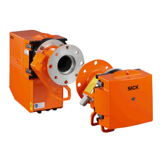
Page 10: Overview Of Standard Components
The evaluation unit carries out the following tasks, for example: O P E R A T I N G I N S T R U C T I O N S |GM35 8009441/YN36/V3-0/2015-08| SICK Subject to change without notice... - Page 11 118. ANSI or DIN flanges provided by the customer can be used alternatively to the flanges supplied. 8009441/YN36/V3-0/2015-08| SICK O P E R A T I N G I N S T R U C T I O N S |GM35 Subject to change without notice...
-
Page 12: Device Components
Cast metal enclosure (IP 67) Sheet metal enclosure (IP 65) Fig. 2: Standard GM35 components O P E R A T I N G I N S T R U C T I O N S |GM35 8009441/YN36/V3-0/2015-08| SICK Subject to change without notice... -
Page 13: Gm35 Options And Accessories
A Data Sheet for the fan heater is also available under Part No. 8 008 330. 8009441/YN36/V3-0/2015-08| SICK O P E R A T I N G I N S T R U C T I O N S |GM35 Subject to change without notice... -
Page 14: Functional Principle
IR spectrum in conjunction with the evaluation algo- rithms used (see “Signal evaluation”, page 15). O P E R A T I N G I N S T R U C T I O N S |GM35 8009441/YN36/V3-0/2015-08| SICK Subject to change without notice... -
Page 15: Signal Evaluation
8009441/YN36/V3-0/2015-08| SICK O P E R A T I N G I N S T R U C T I O N S |GM35 Subject to change without notice... - Page 16 Zero point Check Check point Swivel element (70% fsc) Data recorder O P E R A T I N G I N S T R U C T I O N S |GM35 8009441/YN36/V3-0/2015-08| SICK Subject to change without notice...
-
Page 17: Project Planning Information
69. The main activities are adjustment tasks on the GM35 system related to the application. 8009441/YN36/V3-0/2015-08| SICK O P E R A T I N G I N S T R U C T I O N S |GM35 Subject to change without notice... -
Page 18: Project Planning Checklist
Plan the zero path or order from SICK. Table 1: Project planning checklist O P E R A T I N G I N S T R U C T I O N S |GM35 8009441/YN36/V3-0/2015-08| SICK Subject to change without notice... - Page 19 Always observe and follow the relevant safety information provided for the corresponding texts in these Instructions. Table 1: Project planning checklist 8009441/YN36/V3-0/2015-08| SICK O P E R A T I N G I N S T R U C T I O N S |GM35 Subject to change without notice...
-
Page 20: Initial Onsite Installation
Keep the insulation material removed for later refitting resp. provide new suitable insulation material. O P E R A T I N G I N S T R U C T I O N S |GM35 8009441/YN36/V3-0/2015-08| SICK Subject to change without notice... -
Page 21: Installing The Flanges With Tube
8009441/YN36/V3-0/2015-08| SICK O P E R A T I N G I N S T R U C T I O N S |GM35 Subject to change without notice... - Page 22 Fig. 10: Adjustment device for flange alignment O P E R A T I N G I N S T R U C T I O N S |GM35 8009441/YN36/V3-0/2015-08| SICK Subject to change without notice...
- Page 23 Otherwise the zero path must be adapted, see “Preparing a zero path”, page 8009441/YN36/V3-0/2015-08| SICK O P E R A T I N G I N S T R U C T I O N S |GM35 Subject to change without notice...
-
Page 24: Installation Preparation For The Purge Air Unit
Therefore, design insulation and radiation shielding so that temperature limits are reliably maintained. O P E R A T I N G I N S T R U C T I O N S |GM35 8009441/YN36/V3-0/2015-08| SICK Subject to change without notice... -
Page 25: Installation Preparation For The Evaluation Unit
The prepared cables are connected to the devices during installation or start-up by suitably qualified personnel or by SICK Customer Service. 8009441/YN36/V3-0/2015-08| SICK O P E R A T I N G I N S T R U C T I O N S |GM35 Subject to change without notice... -
Page 26: Electrical Installation Safety Information
Ensure reverse flow is prevented by fitting a (trip) flap or a valve. ▸ Regularly check the functionality of the reverse flow safeguard. O P E R A T I N G I N S T R U C T I O N S |GM35 8009441/YN36/V3-0/2015-08| SICK Subject to change without notice... -
Page 27: Electrical Protection
Relay contact <-> actuation 1376 V AC Table 2: Characteristic data for electric isolation 8009441/YN36/V3-0/2015-08| SICK O P E R A T I N G I N S T R U C T I O N S |GM35 Subject to change without notice... -
Page 28: Laying Connection Lines
Prefabricated with plug-in connector(s) 6 x 0.5 mm Fig. 13: Cable routing diagram O P E R A T I N G I N S T R U C T I O N S |GM35 8009441/YN36/V3-0/2015-08| SICK Subject to change without notice... -
Page 29: Can Bus Wiring
Status and signal cables from the EvU to the connection terminals of the customer's status/signaling equipment can be connected later if necessary. 8009441/YN36/V3-0/2015-08| SICK O P E R A T I N G I N S T R U C T I O N S |GM35 Subject to change without notice... -
Page 30: Installation
O P E R A T I N G I N S T R U C T I O N S |GM35 8009441/YN36/V3-0/2015-08| SICK Subject to change without notice... -
Page 31: Fitting System Components
5 Protect the open end of the purge air hose from humidity or contamination until SR-unit start-up. 8009441/YN36/V3-0/2015-08| SICK O P E R A T I N G I N S T R U C T I O N S |GM35 Subject to change without notice... -
Page 32: Terminal Box (Option)
Mounting holes Fig. 15: Fitting the terminal box O P E R A T I N G I N S T R U C T I O N S |GM35 8009441/YN36/V3-0/2015-08| SICK Subject to change without notice... -
Page 33: Installing The Evaluation Unit
Fastening brackets Fig. 16: Installing the evaluation unit (sheet metal enclosure version) 8009441/YN36/V3-0/2015-08| SICK O P E R A T I N G I N S T R U C T I O N S |GM35 Subject to change without notice... -
Page 34: Installing The Evaluation Unit - Cast Enclosure Version
Fig. 18: Fitting the evaluation unit (cast enclosure) 4 Close and lock the door again. O P E R A T I N G I N S T R U C T I O N S |GM35 8009441/YN36/V3-0/2015-08| SICK Subject to change without notice... -
Page 35: Electrical Connection Of System Components
Fig. 19: Purge air unit: Electrical connections for blower motor and low-pressure monitor 8009441/YN36/V3-0/2015-08| SICK O P E R A T I N G I N S T R U C T I O N S |GM35 Subject to change without notice... -
Page 36: Can Bus Wiring Options
• Terminal box with prefabricated 4 m long cable to SR-unit; a cable provided by the customer is used to connect to the evaluation unit. O P E R A T I N G I N S T R U C T I O N S |GM35 8009441/YN36/V3-0/2015-08| SICK... - Page 37 37; make sure a twisted wire pair is used for CAN-H and CAN-L. 8009441/YN36/V3-0/2015-08| SICK O P E R A T I N G I N S T R U C T I O N S |GM35 Subject to change without notice...
-
Page 38: Electrical Connection In The Evaluation Unit Evu
Analog inputs Fig. 21: Connections on the evaluation unit (cabling provided by the customer) O P E R A T I N G I N S T R U C T I O N S |GM35 8009441/YN36/V3-0/2015-08| SICK Subject to change without notice... - Page 39 ▸ No jumper may be connected to the CAN2 terminator. 8009441/YN36/V3-0/2015-08| SICK O P E R A T I N G I N S T R U C T I O N S |GM35 Subject to change without notice...
- Page 40 EvU Fig. 23: Attaching the CAN bus cable to the evaluation unit O P E R A T I N G I N S T R U C T I O N S |GM35 8009441/YN36/V3-0/2015-08| SICK Subject to change without notice...
-
Page 41: Handling The Evaluation Unit
Warning messages, see Diagnosis mode (diag) ● Malfunction Device malfunction, error message, see Diagnosis mode (diag) 8009441/YN36/V3-0/2015-08| SICK O P E R A T I N G I N S T R U C T I O N S |GM35 Subject to change without notice... -
Page 42: Function Buttons And Menu Overview
Resets parameters to the factory settings Parameter Table 3: Function buttons and menu overview O P E R A T I N G I N S T R U C T I O N S |GM35 8009441/YN36/V3-0/2015-08| SICK Subject to change without notice... -
Page 43: Display Contents
Fig. 25: Menu Operation Measuring meas Measuring 2875 Ref. conditions Hum: wet 8009441/YN36/V3-0/2015-08| SICK O P E R A T I N G I N S T R U C T I O N S |GM35 Subject to change without notice... -
Page 44: Menu Structure Diagnosis
0.4 % Vol pressure and temperature Nullabgleich measurement to reference measurements O P E R A T I N G I N S T R U C T I O N S |GM35 8009441/YN36/V3-0/2015-08| SICK Subject to change without notice... -
Page 45: Menu Structure Configuration
Regress. Funct. CO: Regression function comp.: CO2/H2O Span: 0.50…1.99, Zero: 0…±9999.9 ← 8009441/YN36/V3-0/2015-08| SICK O P E R A T I N G I N S T R U C T I O N S |GM35 Subject to change without notice... -
Page 46: Menu Structure Maintenance Mode (Maint)
Test of digital inputs ← ← System restart Reset: Default parameter settings active O P E R A T I N G I N S T R U C T I O N S |GM35 8009441/YN36/V3-0/2015-08| SICK Subject to change without notice... -
Page 47: Connecting The System Control Unit - Scu
• an Ethernet connection via an SCU operating unit to the evaluation unit. 8009441/YN36/V3-0/2015-08| SICK O P E R A T I N G I N S T R U C T I O N S |GM35 Subject to change without notice... - Page 48 For more information on the SOPAS concept, see the Help menu of SOPAS ET. O P E R A T I N G I N S T R U C T I O N S |GM35 8009441/YN36/V3-0/2015-08| SICK Subject to change without notice...
-
Page 49: Connecting The Gm35 Evaluation Unit Via The Scu Operating Unit
Load the GM35 device description file (e.g., from the device CD). 8009441/YN36/V3-0/2015-08| SICK O P E R A T I N G I N S T R U C T I O N S |GM35 Subject to change without notice... - Page 50 • Perform a network scan, see “Perform a network scan:”, page O P E R A T I N G I N S T R U C T I O N S |GM35 8009441/YN36/V3-0/2015-08| SICK Subject to change without notice...
-
Page 51: Direct Serial Connection To The Gm35 Evaluation Unit
Confirm the selection “Connect to new device” in the “Welcome to SOPAS” with OK. Follow the instructions of the Connection Wizard. 8009441/YN36/V3-0/2015-08| SICK O P E R A T I N G I N S T R U C T I O N S |GM35 Subject to change without notice... - Page 52 Select “Standard Protocol” under interface selection. ▸ Check the protocol settings and adapt when necessary: O P E R A T I N G I N S T R U C T I O N S |GM35 8009441/YN36/V3-0/2015-08| SICK Subject to change without notice...
-
Page 53: Changing The User Level
The current user level in SOPAS ET is shown in the bottom left corner. 8009441/YN36/V3-0/2015-08| SICK O P E R A T I N G I N S T R U C T I O N S |GM35 Subject to change without notice... -
Page 54: Menu Overview (Menu Tree)
Menu GM35/Measured values Fig. 31: Menu: Measured values and Ref. conditions O P E R A T I N G I N S T R U C T I O N S |GM35 8009441/YN36/V3-0/2015-08| SICK Subject to change without notice... -
Page 55: Menu Parameter
• Regression function of the measuring components (zero point, span point) 8009441/YN36/V3-0/2015-08| SICK O P E R A T I N G I N S T R U C T I O N S |GM35 Subject to change without notice... - Page 56 • Physical units (mg/m , % by vol., ppm) • Reference values (temperature, pressure) O P E R A T I N G I N S T R U C T I O N S |GM35 8009441/YN36/V3-0/2015-08| SICK Subject to change without notice...
- Page 57 (yes, no). 8009441/YN36/V3-0/2015-08| SICK O P E R A T I N G I N S T R U C T I O N S |GM35 Subject to change without notice...
- Page 58 • Analog input 2: Pressure: Live Zero (0, 2, 4 mA), unit assignment (hPa), start and end values for the read-in range. • Analog input 3: Unused. O P E R A T I N G I N S T R U C T I O N S |GM35 8009441/YN36/V3-0/2015-08| SICK Subject to change without notice...
- Page 59 • Temperature: Source (Probe, Analog In, Subst.(default value)) and unit. • Pressure: Live Zero source (Probe, Analog In, Subst.(default value)). 8009441/YN36/V3-0/2015-08| SICK O P E R A T I N G I N S T R U C T I O N S |GM35 Subject to change without notice...
-
Page 60: Menu Adjustment
• Measuring Mode: Switches to Measuring mode, e.g. after using Adjust mode. Mirror tracking is active again and therefore current measured values are displayed. O P E R A T I N G I N S T R U C T I O N S |GM35 8009441/YN36/V3-0/2015-08| SICK... - Page 61 This menu serves to recalibrate the system's own pressure and temperature sensors. 8009441/YN36/V3-0/2015-08| SICK O P E R A T I N G I N S T R U C T I O N S |GM35 Subject to change without notice...
- Page 62 • Start Boxmeasuring: Starts filter box measurement. • Abort --> Reset: Stops filter box measurement and discards the results. O P E R A T I N G I N S T R U C T I O N S |GM35 8009441/YN36/V3-0/2015-08| SICK...
- Page 63 • Zero Gas • Manual Adjust CO, • Manual Adjust CO 8009441/YN36/V3-0/2015-08| SICK O P E R A T I N G I N S T R U C T I O N S |GM35 Subject to change without notice...
-
Page 64: Menu Diagnosis
Fig. 43: Menu: Errors/Warnings This menu displays the error messages and warnings as soon as Update is clicked. O P E R A T I N G I N S T R U C T I O N S |GM35 8009441/YN36/V3-0/2015-08| SICK... - Page 65 This menu serves to inquire the control values for the measuring components. 8009441/YN36/V3-0/2015-08| SICK O P E R A T I N G I N S T R U C T I O N S |GM35 Subject to change without notice...
-
Page 66: Menu Maintenance
• Switch between measuring and maintenance. • Trigger check cycle. • Restart system (System reset). O P E R A T I N G I N S T R U C T I O N S |GM35 8009441/YN36/V3-0/2015-08| SICK Subject to change without notice... - Page 67 Fig. 48: Menu: Test Analog Input This menu serves to test the 3 analog inputs. 8009441/YN36/V3-0/2015-08| SICK O P E R A T I N G I N S T R U C T I O N S |GM35 Subject to change without notice...
- Page 68 Fig. 50: Menu: Test Digital Input This menu serves to test the 3 digital inputs. O P E R A T I N G I N S T R U C T I O N S |GM35 8009441/YN36/V3-0/2015-08| SICK Subject to change without notice...
-
Page 69: Start-Up
• The purge air supply must be ready to function. 8009441/YN36/V3-0/2015-08| SICK O P E R A T I N G I N S T R U C T I O N S |GM35 Subject to change without notice... - Page 70 • If the adjustment is carried out at a different location, an additional power supply cable with a suitable device connector for the SR-unit (and possibly EvU) is required. O P E R A T I N G I N S T R U C T I O N S |GM35 8009441/YN36/V3-0/2015-08| SICK...
-
Page 71: Mechanical Preparations For The Sr-Unit And Reflector
Fig. 51: Transport safety device to be removed from the SR-unit 8009441/YN36/V3-0/2015-08| SICK O P E R A T I N G I N S T R U C T I O N S |GM35 Subject to change without notice... -
Page 72: Cleaning Optical Interfaces
Assemble the zero path in the proximity of the SR-unit. O P E R A T I N G I N S T R U C T I O N S |GM35 8009441/YN36/V3-0/2015-08| SICK Subject to change without notice... -
Page 73: Installing The Gm35 System Components
Position the light source of the adjustment device in the device flange and secure using the quick-release fasteners. 8009441/YN36/V3-0/2015-08| SICK O P E R A T I N G I N S T R U C T I O N S |GM35 Subject to change without notice... - Page 74 (screw hidden) Fig. 55: L adjustment to align the flange - purge air fixture (example: reflector flange) O P E R A T I N G I N S T R U C T I O N S |GM35 8009441/YN36/V3-0/2015-08| SICK...
- Page 75 Swivel the SR-unit closed and secure the enclosure using the quick-release fasteners. 8009441/YN36/V3-0/2015-08| SICK O P E R A T I N G I N S T R U C T I O N S |GM35 Subject to change without notice...
- Page 76 Swivel the reflector head closed when necessary and secure the enclosure with the quick-release fasteners. O P E R A T I N G I N S T R U C T I O N S |GM35 8009441/YN36/V3-0/2015-08| SICK Subject to change without notice...
- Page 77 Reflector flange Reflector head Bolt Fig. 58: Installing the reflector head 8009441/YN36/V3-0/2015-08| SICK O P E R A T I N G I N S T R U C T I O N S |GM35 Subject to change without notice...
-
Page 78: Electrical Connections
CAN cable to EvU Fig. 60: Cable connections on the SR-unit (underside) O P E R A T I N G I N S T R U C T I O N S |GM35 8009441/YN36/V3-0/2015-08| SICK Subject to change without notice... -
Page 79: Zero Adjust
Press the maint button, select menu item ADJ. OPT. ALIGN and call up with Enter 8009441/YN36/V3-0/2015-08| SICK O P E R A T I N G I N S T R U C T I O N S |GM35 Subject to change without notice... -
Page 80: Performing Zero Adjust
Switch to Diagnosis mode and rectify the problem, see “Troubleshooting and Clearing Malfunctions”, page 104. O P E R A T I N G I N S T R U C T I O N S |GM35 8009441/YN36/V3-0/2015-08| SICK Subject to change without notice... -
Page 81: Starting Measuring Operation
▸ Switch the purge air supply on. 8009441/YN36/V3-0/2015-08| SICK O P E R A T I N G I N S T R U C T I O N S |GM35 Subject to change without notice... -
Page 82: Sender/Receiver Unit And Reflector Start-Up
▸ Connect the functional earth cable to the screw terminal provided. O P E R A T I N G I N S T R U C T I O N S |GM35 8009441/YN36/V3-0/2015-08| SICK Subject to change without notice... - Page 83 Reactivate Measuring mode: – Press meas Regular measuring operation now starts. 8009441/YN36/V3-0/2015-08| SICK O P E R A T I N G I N S T R U C T I O N S |GM35 Subject to change without notice...
-
Page 84: Installing The Weatherproof Cover For The Sr-Unit
The weatherproof cover for the purge air unit is available as an accessory. It comprises a cover and a lock set. O P E R A T I N G I N S T R U C T I O N S |GM35 8009441/YN36/V3-0/2015-08| SICK... -
Page 85: Evaluation Unit Start-Up
See “Handling the Evaluation Unit”, page 8009441/YN36/V3-0/2015-08| SICK O P E R A T I N G I N S T R U C T I O N S |GM35 Subject to change without notice... -
Page 86: Setting Up The Scu System Control Unit
H2O temp. detec. F013 div. Zero F014 H2O div. Zero F015 VISOR fault O P E R A T I N G I N S T R U C T I O N S |GM35 8009441/YN36/V3-0/2015-08| SICK Subject to change without notice... - Page 87 VISOR amplifier Software version CUEVETTE range Flag_062 Probe message Probe com. 8009441/YN36/V3-0/2015-08| SICK O P E R A T I N G I N S T R U C T I O N S |GM35 Subject to change without notice...
-
Page 88: Maintenance
O P E R A T I N G I N S T R U C T I O N S |GM35 8009441/YN36/V3-0/2015-08| SICK... -
Page 89: Preparation And General Preparatory Work
Prefabricated cables are available as spare parts. 8009441/YN36/V3-0/2015-08| SICK O P E R A T I N G I N S T R U C T I O N S |GM35 Subject to change without notice... -
Page 90: Cleaning The Optical Interface (Window) On The Sr-Unit
Optical interface (front window) Fig. 67: Optical interface (window) on the SR-unit O P E R A T I N G I N S T R U C T I O N S |GM35 8009441/YN36/V3-0/2015-08| SICK Subject to change without notice... -
Page 91: Cleaning The Optical Interface (Window) On The Reflector
“Starting measuring operation”, page [1] Depending on the existing zero path 8009441/YN36/V3-0/2015-08| SICK O P E R A T I N G I N S T R U C T I O N S |GM35 Subject to change without notice... -
Page 92: Checking Optical Alignment
Optimum alignment Valid field Fig. 69: Aligning the optical axis O P E R A T I N G I N S T R U C T I O N S |GM35 8009441/YN36/V3-0/2015-08| SICK Subject to change without notice... -
Page 93: Checking The Ir Source
A zero adjust must be carried out after installing a new IR source, see “Performing zero adjust”, page 8009441/YN36/V3-0/2015-08| SICK O P E R A T I N G I N S T R U C T I O N S |GM35 Subject to change without notice... -
Page 94: Maintenance Work On The Purge Air Supply
▸ Make sure the dummy plug for the Y-distributor on the purge air unit is secure. O P E R A T I N G I N S T R U C T I O N S |GM35 8009441/YN36/V3-0/2015-08| SICK... -
Page 95: Checking And Replacing The Purge Air Filter
Fit the filter housing cover and align it with the filter housing so that the two snap locks on the side click into position. 8009441/YN36/V3-0/2015-08| SICK O P E R A T I N G I N S T R U C T I O N S |GM35 Subject to change without notice... -
Page 96: Restarting And Checking The Purge Air Unit
Carefully reattach the purge air hose to the corresponding purge air connection on the fixture and secure. O P E R A T I N G I N S T R U C T I O N S |GM35 8009441/YN36/V3-0/2015-08| SICK... -
Page 97: Evaluation Unit (Evu)
If the evaluation unit is damaged (e.g. LC display failure): ▸ Contact SICK AG Service or the local sales representative. 8009441/YN36/V3-0/2015-08| SICK O P E R A T I N G I N S T R U C T I O N S |GM35 Subject to change without notice... -
Page 98: Box Measuring
Take care not to damage the humidity sensor of the SR-unit! ▸ Fit the reflector for the GM35. O P E R A T I N G I N S T R U C T I O N S |GM35 8009441/YN36/V3-0/2015-08| SICK Subject to change without notice... - Page 99 Filter box Test gas cylinder Fig. 71: Installing the filter box 8009441/YN36/V3-0/2015-08| SICK O P E R A T I N G I N S T R U C T I O N S |GM35 Subject to change without notice...
-
Page 100: Restart Measuring Mode
▸ Refit the SR-unit back onto the measuring point in the correct position. O P E R A T I N G I N S T R U C T I O N S |GM35 8009441/YN36/V3-0/2015-08| SICK Subject to change without notice... -
Page 101: Filter Box Measurement For Checking The Measuring Ducts Of H 2 O And Co 2
GM35, are used. Higher extinction values exceed the warning or malfunction threshold for not sufficient signal level. 8009441/YN36/V3-0/2015-08| SICK O P E R A T I N G I N S T R U C T I O N S |GM35 Subject to change without notice... -
Page 102: Carrying Out Measurement
Filter box GM35 SR-unit Fig. 73: Installing the filter box O P E R A T I N G I N S T R U C T I O N S |GM35 8009441/YN36/V3-0/2015-08| SICK Subject to change without notice... -
Page 103: Restart Measuring Mode
Refit the SR-unit back onto the measuring point in the correct position. 8009441/YN36/V3-0/2015-08| SICK O P E R A T I N G I N S T R U C T I O N S |GM35 Subject to change without notice... -
Page 104: Troubleshooting And Clearing Malfunctions
“Purge air failure”, page 105 describes the necessary emergency and protective measures. O P E R A T I N G I N S T R U C T I O N S |GM35 8009441/YN36/V3-0/2015-08| SICK Subject to change without notice... -
Page 105: Purge Air Failure
• Flange cover to seal off the flange opening when the measuring system is removed. 8009441/YN36/V3-0/2015-08| SICK O P E R A T I N G I N S T R U C T I O N S |GM35 Subject to change without notice... -
Page 106: Integrated Monitoring And Diagnosis System
Then localize the possible cause and clear the malfunction; see Troubleshooting Table. O P E R A T I N G I N S T R U C T I O N S |GM35 8009441/YN36/V3-0/2015-08| SICK Subject to change without notice... -
Page 107: Troubleshooting And Clearing Malfunctions, Evaluation Unit
If the same error message occurs again, replace the EvU and contact Service 8009441/YN36/V3-0/2015-08| SICK O P E R A T I N G I N S T R U C T I O N S |GM35 Subject to change without notice... -
Page 108: Error Messages
Clean optical surfaces, see page 90/page above dynamic range ▸ Contact Service. O P E R A T I N G I N S T R U C T I O N S |GM35 8009441/YN36/V3-0/2015-08| SICK Subject to change without notice... - Page 109 ▸ If the error cannot be cleared: Contact Service. 8009441/YN36/V3-0/2015-08| SICK O P E R A T I N G I N S T R U C T I O N S |GM35 Subject to change without notice...
-
Page 110: Warning Messages For The Gm35 Sr-Unit
• Signal distorted. Contact Service if necessary. • Warming up phase. O P E R A T I N G I N S T R U C T I O N S |GM35 8009441/YN36/V3-0/2015-08| SICK Subject to change without notice... - Page 111 MS and check value,see “Checking the IR cycle; max. value 255. source”, page 8009441/YN36/V3-0/2015-08| SICK O P E R A T I N G I N S T R U C T I O N S |GM35 Subject to change without notice...
-
Page 112: Further Tips On Troubleshooting
Outer plug-in connectors on SR-unit. ▸ Inner plug-in connectors in SR-unit. O P E R A T I N G I N S T R U C T I O N S |GM35 8009441/YN36/V3-0/2015-08| SICK Subject to change without notice... -
Page 113: Technical Data, Consumables And Spare Parts
Extremely small or large end values for different components cannot be combined in all cases. 8009441/YN36/V3-0/2015-08| SICK O P E R A T I N G I N S T R U C T I O N S |GM35 Subject to change without notice... -
Page 114: Gm35 System Component
∅ Dimensions (L x 220 x 240 mm Weight 7 kg O P E R A T I N G I N S T R U C T I O N S |GM35 8009441/YN36/V3-0/2015-08| SICK Subject to change without notice... - Page 115 IP 65 / NEMA 4x Dimensions see dimension drawing from page 118 8009441/YN36/V3-0/2015-08| SICK O P E R A T I N G I N S T R U C T I O N S |GM35 Subject to change without notice...
-
Page 116: Dimension Drawings
10.2.1 GM35 SR-unit dimensions Fig. 77: GM35 SR-unit dimensions 531,7 99,7 O P E R A T I N G I N S T R U C T I O N S |GM35 8009441/YN36/V3-0/2015-08| SICK Subject to change without notice... -
Page 117: Purge Air Fixtures Dimensions
Fig. 78: Purge air fixtures for SR-unit and reflector dimensions 10.2.3 GM35 reflector dimensions Fig. 79: Reflector dimensions 8009441/YN36/V3-0/2015-08| SICK O P E R A T I N G I N S T R U C T I O N S |GM35 Subject to change without notice... -
Page 118: Flange With Tube Dimensions
Fig. 81: Dimensions of GM35 evaluation unit, sheet metal version 97,5 O P E R A T I N G I N S T R U C T I O N S |GM35 8009441/YN36/V3-0/2015-08| SICK Subject to change without notice... -
Page 119: Dimension Drawing For Gm35 Evaluation Unit, Cast Metal Enclosure
Fig. 82: Dimensions of GM35 evaluation unit, cast metal enclosure version 10.2.7 Purge air unit dimensions Fig. 83: SLV4 dimensions 8009441/YN36/V3-0/2015-08| SICK O P E R A T I N G I N S T R U C T I O N S |GM35 Subject to change without notice... -
Page 120: Weatherproof Cover For Purge Air Unit(S) Dimensions
Fig. 85: Weatherproof cover for GM35 SR-unit 576,3 636,4 25,2 525,8 O P E R A T I N G I N S T R U C T I O N S |GM35 8009441/YN36/V3-0/2015-08| SICK Subject to change without notice... -
Page 121: Terminal Box For Can Bus Connection Dimensions
Lithium battery 3.00 V CR2032 2008475 Drying agent cartridge, reflector unit 8009441/YN36/V3-0/2015-08| SICK O P E R A T I N G I N S T R U C T I O N S |GM35 Subject to change without notice... -
Page 122: Spare Parts For The Sender/Receiver Unit
Cover, SR enclosure 2023527 Plug, mains connection 2020020 CAN connection, SR-unit, plug O P E R A T I N G I N S T R U C T I O N S |GM35 8009441/YN36/V3-0/2015-08| SICK Subject to change without notice... -
Page 123: Spare Parts For The Reflector Unit
Fig. 88: Position of spare parts for the purge air fixture, SR side 8009441/YN36/V3-0/2015-08| SICK O P E R A T I N G I N S T R U C T I O N S |GM35 Subject to change without notice... -
Page 124: Spare Parts For Purge Air Fixture - Reflector Side
2 017 329 Hinge pin 6 010 378 Lithium battery 3.00 V CR2032 O P E R A T I N G I N S T R U C T I O N S |GM35 8009441/YN36/V3-0/2015-08| SICK Subject to change without notice... -
Page 125: Spare Parts For Purge Air Unit
Hinge pin for GM35 flange fixture 4 023 743 Sealing tape 8009441/YN36/V3-0/2015-08| SICK O P E R A T I N G I N S T R U C T I O N S |GM35 Subject to change without notice... - Page 126 Motor with electronic board, NPR, 2 023 515 Fig. 90: Spare parts assignment for GM35 SR-unit O P E R A T I N G I N S T R U C T I O N S |GM35 8009441/YN36/V3-0/2015-08| SICK...
- Page 127 Purge air fixture, reflector side Fig. 91: Spare parts assignment for GM35 purge air fixtures 8009441/YN36/V3-0/2015-08| SICK O P E R A T I N G I N S T R U C T I O N S |GM35 Subject to change without notice...
- Page 128 TECHNICAL DATA, CONSUMABLES AND SPARE PARTS O P E R A T I N G I N S T R U C T I O N S |GM35 8009441/YN36/V3-0/2015-08| SICK Subject to change without notice...
- Page 129 - Parameters, setting ................ 42 - Serial No..................42 Password .................... 53 8009441/YN36/V3-0/2015-08| SICK O P E R A T I N G I N S T R U C T I O N S | GM35 Subject to change without notice...
- Page 130 E-Mail sales@sick.co.nz United Arab Emirates China Norway E-Mail sick@sick.no USA/Mexico Denmark Poland E-Mail sick@sick.dk Finland Romania Vietnam France Russia Gemany Singapore Great Britain Slovakia E-Mail mail@sick-sk.sk Hong Kong Slovenia Hungary South Africa www.sick.com SICK AG | Waldkirch | Germany | www.sick.com...
Need help?
Do you have a question about the GM35 and is the answer not in the manual?
Questions and answers