Sign In
Upload
Manuals
Brands
SICK Manuals
Measuring Instruments
GM901
SICK GM901 Manuals
Manuals and User Guides for SICK GM901. We have
4
SICK GM901 manuals available for free PDF download: Operating Instructions Manual, Manual
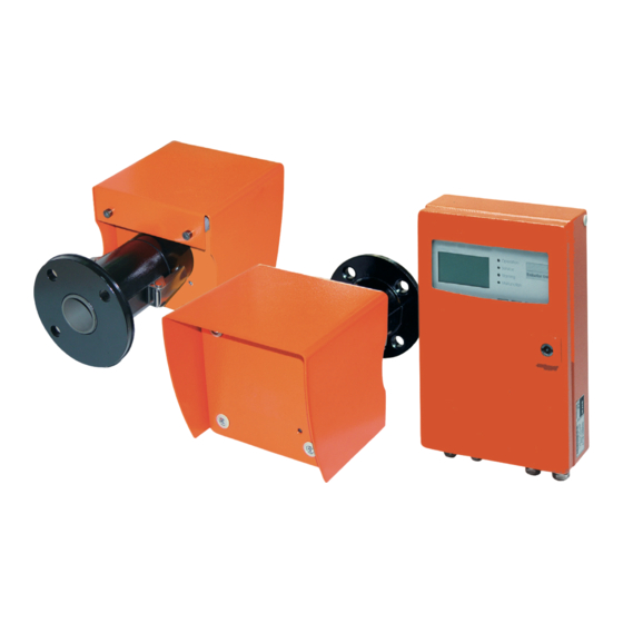
SICK GM901 Operating Instructions Manual (94 pages)
Brand:
SICK
| Category:
Measuring Instruments
| Size: 3 MB
Table of Contents
Table of Contents
3
About this Document
7
Function of this Document
7
Scope of Application
7
Target Groups
7
Further Information
7
Symbols and Document Conventions
8
Warning Symbols
8
Warning Levels and Signal Words
8
Information Symbols
8
Data Integrity
8
For Your Safety
10
Intended Use
10
Responsibility of User
10
Troubleshooting Precautions
11
Basic Measures to Prevent Property Damage and Injury to Persons
11
Environment-Friendly Behavior
11
Responsibility for System Safety
11
Protection against Hazards through Gases
12
Protective Measures against Escaping Gases
12
Noxious Gases in Device/Module
12
Hot Gases in Ambient Conditions with Overpressure
12
Behavior after Purge Air Failure
12
Electrical Safety
13
Protection against Hazards through Electrical Equipment
13
Electrical Safety through Circuit Breakers Properly Installed
13
Electrical Safety through Lines with Correct Rating
13
Grounding the Devices
13
Product Description
14
Product Identification
14
Product Features
14
Cross-Sensitivities
14
Device Variants
17
Layout
18
Standard Scope of Delivery
19
Control Unit
19
PROFIBUS Interface (if Installed)
19
Optional Accessories
20
Transport and Storage
21
Storage
21
Mounting
22
Safety
22
Information on Lifting and Carrying
22
Information on Assembly (Wall Fitting)
22
Preparing the Sampling Point
22
Check Scope of Delivery
22
Fitting the Flange with Pipe
23
Installing the Standard Flange
24
Measuring Distance Definition
25
Assembly Variant for Brick Stacks
26
Assembly Variant for Thin-Walled Ducts
26
Installing the Purge Air Unit
27
Installing the GM901 CO Measuring Device
27
Aligning the Optical Axis
28
Installing the Sender and Receiver
29
Installing the Weather Protection Hood for the GM901
30
Installing the Control Unit
31
Electrical Installation
32
Project Planning
32
Electrical Wiring for the Standard Version
33
Electrical Wiring with Connection Unit
34
Electrical Connection of the Purge Air Motor
34
Electrical Wiring: Control Unit - Standard
35
Electrical Wiring: Control Unit - PROFIBUS
36
Electrical Connections of the Evaluation Unit
37
Commissioning
38
Requirements for Commissioning
38
Calibration
39
Prerequisites for Zero Adjust
39
Calibrating the GM901 Standard
39
Calibrating the GM901 with Extended Calibration
40
Zero Adjust
41
SPAN Test (Optional)
42
Fitting the Measuring Device on the Duct
43
Preset Parameter Values
44
Operation
45
Operating and Display Elements
45
Control Unit Operating Panel
45
Display
46
Status Leds
46
Menus
47
Measuring Mode
47
Diagnosis
48
Viewing Malfunction Messages
48
Viewing Warning Messages
49
Viewing Sensor Values
50
Parameters
51
Changing the Physical Unit
52
Setting the Humidity Correction
53
Changing the Response Time
54
Changing the Measuring Range
55
Changing the Limit Value
56
Changing the Flange - Flange Measuring Distance and the Active Measuring Distance
57
Temperature
58
Setting the Humidity Content in Sample Gas
62
Setting the Sample Gas Pressure
63
Changing the Live Zero Value of the Analog Output (Analog Out)
64
Changing the Calibration Values
65
Median Filter
66
Device Characteristic Data (Device)
66
Service
68
Calibration
68
Performing Zero Adjust
69
SPAN Test
70
Maintenance
71
Reset System
71
Maintenance Mode
72
Test Analog Output
73
Test Relay
74
Reset Parameter
75
Connecting the PROFIBUS During Commissioning (if Installed)
75
Maintenance
76
General
76
Maintenance Interval of Individual Components of GM901 CO Systems
76
Troubleshooting
77
Warnings
77
Malfunctions
78
Further Tips on Troubleshooting
79
Troubleshooting on the Sender
79
Troubleshooting on Receiver
80
Troubleshooting on the Control Unit
81
Shutting down
83
Disassembling the Sender and Receiver
83
Deinstallation
83
Disposal
83
Technical Data
84
System GM901-05
84
Sender Unit
84
Receiver Unit
84
Control Unit AWE, Standard Version (Part No.: 2020428, 2021433)
85
Control Unit AWE with Extended Connectivity (Part No.: 2027607, 2084045)
86
Connection Unit
86
Dimension Drawing, Sender/Receiver Unit
87
Dimensional Drawing, Control Unit
88
Dimension Drawing, Connection Unit
89
Dimension Drawing, Flange with Tube, DN125
89
Dimension Drawing, Weather Protection Hood, Sender/Receiver Unit
90
Order Data
91
Spare Parts
91
Options, Accessories
91
Conformities
92
Advertisement
SICK GM901 Operating Instructions Manual (78 pages)
Carbon Monoxide Measuring Device
Brand:
SICK
| Category:
Measuring Instruments
| Size: 4 MB
Table of Contents
Table of Contents
3
1 About this Document
6
2 For Your Safety
7
Intended Use
7
Permissible Users
7
Correct Handling
7
Troubleshooting Precautions
8
Basic Measures to Prevent Property Damage and Injury to Persons
8
Environment-Friendly Behavior
8
Responsibility for System Safety
8
Protection against Hazards through Gases
9
Protective Measures against Escaping Gases
9
Noxious Gases in Device/Module
9
Hot Gases in Ambient Conditions with Overpressure
9
Behaviour by Purge Air Failure
9
Electrical Safety
10
Protection against Hazards through Electrical Equipment
10
Electrical Safety through Circuit Breakers Properly Installed
10
Electrical Safety through Lines with Correct Rating
10
Grounding the Devices
10
3 Overview GM901
11
Device Component Overview
11
Standard Scope of Delivery
12
Optional Accessories
12
Evaluation Unit
12
PROFIBUS Interface (if Installed)
13
4 Assembly
14
Safety Information for Assembly
14
Information on Lifting and Carrying
14
Information on Assembly (Wall Fitting)
14
Fitting the Flange with Pipe
15
Installing the Standard Flange
16
Measuring Path Definition
17
Assembly Variant for Brick Stacks
17
Assembly Variant for Thin-Walled Ducts
18
Installing the Purge Air Unit
19
Installing the GM901 CO Measuring Device
20
Aligning the Optical Axis
21
Installing the Sender and Receiver
22
Installing the Weatherproof Cover for the GM901
22
Installing the Evaluation Unit
24
5 Electrical Installation
25
Electrical Installation Project Planning
25
Electrical Wiring for the Standard Version
26
Electrical Wiring with Connection Unit
27
Electrical Connection of the Purge Air Motor
28
Electrical Wiring: Evaluation Unit - Standard
30
Electrical Wiring: Evaluation Unit - PROFIBUS
31
Electrical Connections of the Evaluation Unit
32
6 Commissioning
33
Requirements for Commissioning
33
Operating Panel of the Evaluation Unit
33
Display
33
Arrow Keys
33
Function Keys and Submenus
34
Zero Adjust
35
Prerequisites for Zero Adjust
35
Creating the Zero Path
36
Starting Zero Adjust
36
Fitting the GM901 CO Measuring Device on the Duct
36
Test Cells
36
Determining the Test Values
37
Perform the SPAN Tests
37
Basic Parameters Set
38
7 Configuring
39
Diagnosis
39
Configuring
41
Settings
41
Physical Unit
41
Scaling
42
Response Time
43
Measuring Range
44
Limit Value
45
Measuring Path Flange - Flange and Active Measuring Path
46
Temperature
47
Moisture
50
Pressure
50
Analog Output
51
Calibration
52
Device Data
53
Service
55
Calibration
55
Zero Adjust
55
SPAN Test
57
Maintenance
57
Reset System
58
Maintenance Mode
58
Test Analog Output
60
Test Relay
61
Resetting Parameters
62
Measuring Mode
62
Connecting the PROFIBUS During Commissioning (if Installed)
63
8 Shutting down
64
Disassembling the Sender and Receiver
64
Deinstallation
64
9 Technical Data
65
Technical Data Overview
65
Technical Data of the Sender and Receiver of the GM901-5
65
Evaluation Unit
65
Specifications for Optional Voltage Supply Unit
65
Specifications on Electric Isolation
66
Conformities
66
Dimensions - Sender/Receiver GM901-05
67
Dimensioned Drawing - Evaluation Unit
68
10 Warnings and Malfunctions
69
Warnings
69
Malfunctions
70
Further Tips on Troubleshooting
71
Troubleshooting on the Sender
71
Troubleshooting on Receiver
72
Troubleshooting on the Evaluation Unit
73
Remote Diagnosis
74
11 Spare Parts and Accessories
75
Spare Parts
75
Options, Accessories
75
12 General Maintenance
76
General
76
Maintenance Interval of Individual Components of GM901 CO Systems
76
SICK GM901 Operating Instructions Manual (74 pages)
Carbon Monoxide Measuring Device
Brand:
SICK
| Category:
Measuring Instruments
| Size: 1 MB
Table of Contents
Table of Contents
3
1 Safety Information
6
Intended Use
6
Qualified Personnel
6
Correct Handling
6
Safety Devices and Measures
7
Responding to Purge-Air Failure
7
Environmental Information
7
2 GM901 Overview
8
Components Overview
8
Standard Scope of Supply
9
Optional Accessories
9
Evaluation Unit
9
PROFIBUS Interface
10
3 Mounting
11
Fitting of the Flange with Tube
11
Mounting the Standard Flange
12
Defining the Measuring Path
13
Variant Installation for Brick Ducts
13
Variant Installation for Thin-Walled Ducts
14
Mounting the Purge Air Unit
15
Mounting the CO Measuring Device GM901
16
Aligning the Optical Axis
17
Mounting the Sender and Receiver
18
Installing the Weatherproof Cover for the GM901
19
Mounting the Evaluation Unit
20
4 Electrical Installation
21
Planning Guide for Electrical Installation
21
Electric Wiring for Standard Version
22
Electrical Wiring for Evaluation Unit
23
Electrical Connections for the Purge Air Motor
24
Power Supply and Signal Cables for the Evaluation Unit
26
Electrical Wiring of the Evaluation Unit - PROFIBUS
27
Electrical Connections Inside the Connection Unit
28
5 Commissioning
29
Requirements for Commissioning
29
Control Elements of the Evaluation Unit
29
Function Keys and Sub Menus
30
Zero-Point Adjustment
31
Conditions for the Zero-Point Adjustment
31
Establishing the Zero-Point Comparison Path
31
Start the Zero-Point and Check-Point Adjustment
32
Mounting the GM901 CO Monitor on the Duct
32
Test Cells
32
Determining the Test Concentration
33
Performing the SPAN Test
33
Default Parameter Settings
34
6 Setting the Parameters
35
Diagnosis
35
Setting the Parameters
37
Settings
37
Device Data
49
Service
49
Calibration
51
Zero-Point Adjustment
51
SPAN-Test
53
Maintenance
54
Reset System
54
Maintenance Mode
55
Reset Parameter
57
Measuring Mode
58
Connection of the PROFIBUS for Commissioning
58
7 Decommissioning of the GM901
59
Dismantling the Sender and the Receiver
59
Decommissioning
59
8 Technical Data
61
Overview
61
Sender and Receiver of the GM901-5
61
Evaluation Unit
61
Dimensioned Drawing - Sender
62
Dimensioned Drawing - Evaluation Unit
63
9 Warnings and Malfunctions
64
Warnings
64
Malfunctions
65
Further Troubleshooting Tips
66
Troubleshooting on the Sender
66
Troubleshooting on the Receiver
67
Troubleshooting on the Evaluation Unit
68
No Response from Device
68
Communication Error between the Evaluation Unit and Receiver
69
Sensor Values
69
Remote Diagnosis
69
10 Spare Parts, Accessories
71
10.1 Spare Parts
71
10.2 Options, Accessories
71
Advertisement
SICK GM901 Manual (24 pages)
CO Monitor
Brand:
SICK
| Category:
Measuring Instruments
| Size: 4 MB
Table of Contents
Table of Contents
3
1 Overview
4
Benefits of the GM 901
4
Applications
4
Standard Components
5
Accessories/Options
6
Accessories for the GM 901
7
Options
8
2 Instructions for Project Planning
9
Checklist
9
Installation Sequence
10
3 Preparations for Installation
11
Preparations for Mounting
11
Installation Proposal
11
Instructions for Mounting the Flange with Pipe
11
Installation on Steel Ducts
12
Installation on Brick Ducts
12
Installation on Thin-Walled Ducts
12
Auxiliary Pipe for Measuring Paths of Less than 2 M
13
Aligning the Flange with the Optical Alignment Aid
13
Preparations for Electrical Installation
14
Wiring Specifications/Interfaces to the Evaluation Unit
14
Connection Unit (Accessory)
15
Purge-Air Unit (Option)
16
4 Preparations for Startup
17
Zero Calibration
17
SPAN Test (Option)
17
Test Cells
17
Calculating the Test Values
18
5 Technical Data
19
Device Data
19
Accessories
20
Options
20
Dimensioned Drawings
21
Transmitter and Receiver
21
Evaluation Unit
22
Purge-Air Unit
23
Air Filter Assembly
23
Advertisement
Related Products
SICK GM901-02
SICK GM700-05
SICK GM700-08
SICK GM32-1
SICK GM32-7
SICK GM32-9
SICK GM32-TRS-PE05
SICK GM35-5
SICK GM32 TRS
SICK GM35-2
SICK Categories
Accessories
Security Sensors
Measuring Instruments
Scanner
Barcode Reader
More SICK Manuals
Login
Sign In
OR
Sign in with Facebook
Sign in with Google
Upload manual
Upload from disk
Upload from URL