Sign In
Upload
Download
Table of Contents
Contents
Add to my manuals
Delete from my manuals
Share
URL of this page:
HTML Link:
Bookmark this page
Add
Manual will be automatically added to "My Manuals"
Print this page
×
Bookmark added
×
Added to my manuals
Manuals
Brands
Pfeiffer Vacuum Manuals
Water Pump
ACP 40 Series
Operating instructions manual
Pfeiffer Vacuum ACP 40 Series Operating Instructions Manual
Multi-stage roots pump, air cooled
Hide thumbs
1
2
Table Of Contents
3
4
5
6
7
8
9
10
11
12
13
14
15
16
17
18
19
20
21
22
23
24
25
26
27
28
29
30
31
32
33
34
35
36
37
38
39
40
41
42
43
44
45
46
47
48
49
50
51
52
53
54
55
56
page
of
56
Go
/
56
Contents
Table of Contents
Bookmarks
Table of Contents
Table of Contents
1 About this Manual
Validity
Products Concerned
Applicable Documents
Conventions
Pictographs
Target Group
Instructions in the Text
Labels
Fig. 1: Safety Label Locations
2 Safety
General Safety Instructions
Safety Instructions
Precautions
Intended Use
Foreseeable Misuse
3 Transportation and Storage
Receipt of the Product
Handling
Storage
4 Product Description
Product Identification
Scope of Delivery
Differences between Pump Versions
Human/Machine Interface
Fig. 2: ACP 28 - 40 - CV Version with Single-Phase Frequency Converter
Fig. 3: ACP 28 - 40 - Versions SD - SH - G - CP - LG with Single-Phase Frequency Converter
5 Installation
Connecting to the Pumping Line
Connection on the Pump Inlet Side
Connection on the Pump Exhaust Side
Connecting CP Version Pumps
Connecting the Purge Circuit
Check that the Installation Is Leaktight
Electrical Connection
Customer Electrical Installation Protection
Mains Connection
Remote Connector Wiring
Digital Input Wiring
Setting of the Rotation Speed
Digital Output Wiring
Fig. 4: Remote Control Connector Wiring
Wiring the RS-485 Serial Link
Connections
Setting
Fig. 5: Male 15-Pin RS-485 Connector
Command List
6 Operation
Preliminary Precautions for Use
Matrix Gas/Applications
Different Control Modes
Local Mode Operation
Fig. 6: Cover Plug with Strap for Operation in Local Mode
Remote Control Mode Operation
Operation in RS-485 Link Mode
Operation Monitoring
Gas Ballast Operation
Purge Operation
Gas Ballast and Purge Operation on CV Version
7 Maintenance
Maintenance Safety Instructions
Maintenance Frequency
On-Site Maintenance
Exchange Procedure for Replacement Products
Disconnecting the Pump from the Installation
Preparing the Pump for Shipping
8 Decommissioning
Shutting down for Longer Periods
Recommissioning
Disposal
9 Malfunctions
Trouble at Pump Start-Up
The Pump Runs Incorrectly
10 Service Solutions from Pfeiffer Vacuum
11 Accessories
12 Technical Data and Dimensions
General
Technical Characteristics
1Environmental Conditions
2Nitrogen Characteristics
3Electrical Characteristics
Dimensions
Fig. 7: Dimensions ACP 28 - 40 Versions SD - SH - LG - G
Fig. 8: Dimensions ACP 28 - 40 Versions CV
Fig. 9: Dimensions ACP 28 - 40 Versions CP
Weight Distribution and Center of Gravity
Fig. 10: Wheel Kit Dimensions
Fig. 11: Fastening Kit Dimensions
Load on Foot with Fastening Kit
ETL Mark
Declaration of Conformity
Advertisement
Quick Links
1
Trouble at Pump Start-Up
Download this manual
OPERATING INSTRUCTIONS
EN
Translation of the Original
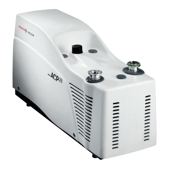
ACP 28 - 40
Multi-stage Roots pump, air cooled
Table of
Contents
Previous
Page
Next
Page
1
2
3
4
5
Advertisement
Table of Contents
Need help?
Do you have a question about the ACP 40 Series and is the answer not in the manual?
Ask a question
Questions and answers
Related Manuals for Pfeiffer Vacuum ACP 40 Series
Water Pump Pfeiffer Vacuum ACP 15 Operating Instructions Manual
Dry compact multi-stage roots pump (44 pages)
Water Pump Pfeiffer Vacuum ACP 15 Operating Instructions Manual
Multi-stage roots pump, air cooled (46 pages)
Water Pump Pfeiffer Vacuum ACP 28 Series Operating Instructions Manual
Multi-stage roots pump, air cooled (56 pages)
Water Pump Pfeiffer Vacuum ACP 120G Operating Instructions Manual
Industrial multistage roots dry pump (52 pages)
Water Pump Pfeiffer Vacuum ACP 120G Installation Instructions Manual
Multistage roots pump, industrial and dry (56 pages)
Water Pump Pfeiffer Vacuum ACP 28R Supplementary Information
(12 pages)
Water Pump Pfeiffer Vacuum ACP 90 Operating Instructions Manual
Multi-stage roots pump, air cooled (52 pages)
Water Pump Pfeiffer Vacuum A 124H Operating Instructions Manual
Multi-stage roots pump for harsh applications (92 pages)
Water Pump Pfeiffer Vacuum Adixen A3H Series Operating Instructions Manual
Multistage roots dry pump (144 pages)
Water Pump Pfeiffer Vacuum adixen ATH 500 M Operating Instructions Manual
Magnetically levitated turbopumps (86 pages)
Water Pump Pfeiffer Vacuum ATH 2800 MT Operating Instructions Manual
Turbopumps (61 pages)
Water Pump Pfeiffer Vacuum ATH 2300 M Operating Instructions Manual
Magnetically levitated turbopump (58 pages)
Water Pump Pfeiffer Vacuum ATH 1603 M Operating Instructions Manual
Magnetically levitated turbomolecular pump (56 pages)
Water Pump Pfeiffer Vacuum ATH 500 M Operating Instructions Manual
Magnetically levitated turbopump (78 pages)
Water Pump Pfeiffer Vacuum A3P Series Operating Instructions Manual
(129 pages)
Water Pump Pfeiffer Vacuum A 100 L Operating Instructions Manual
Multi-stage roots pump, compact, for light duty applications (62 pages)
This manual is also suitable for:
Acp 40 sd
Acp 28 series
Acp 28 sd
Acp 28 g
Acp 28 cv
Acp 40 cv
...
Show all
Acp 40 g
Acp 28 sh
Acp 40 sh
Acp 28 lg
Acp 40 lg
Acp 28 cp
Acp 40 cp
Table of Contents
Save PDF
Print
Rename the bookmark
Delete bookmark?
Delete from my manuals?
Login
Sign In
OR
Sign in with Facebook
Sign in with Google
Upload manual
Upload from disk
Upload from URL


Need help?
Do you have a question about the ACP 40 Series and is the answer not in the manual?
Questions and answers