Table of Contents
Advertisement
Quick Links
MP145E
Q-521 Miniature Linear Stage
User Manual
Version: 1.0.1
PI miCos GmbH, Freiburger Strasse 30, 79427 Eschbach, Germany
Phone +49 7634 5057-0, Fax +49 7634 5057-99, Email info@pimicos.com, www.pi.ws
Date: 29.01.2019
This document describes the following products:
Q-521
Q-Motion miniature linear stage, piezoelectric
inertia drive
This document applies to various model
versions of the Q-521. The model version of the
Q-521 is coded in the order number by means
of three characters after a period. Meaning of
the characters and valid values:
First character after the period:
Travel range
1 = 12 mm
2 = 22 mm
3 = 32 mm
Second character after the period:
Sensor equipment
0 = without sensor
3 = with sensor, sensor resolution 4 nm
4 = with sensor, sensor resolution 1 nm
Third character after the period:
Vacuum suitability
-6
0 = suitable to 10
hPa
-9
U = suitable to 10
hPa
Advertisement
Table of Contents

Related Manuals for PI Q-521


Summary of Contents for PI Q-521
- Page 1 4 = with sensor, sensor resolution 1 nm Third character after the period: Vacuum suitability 0 = suitable to 10 U = suitable to 10 PI miCos GmbH, Freiburger Strasse 30, 79427 Eschbach, Germany Phone +49 7634 5057-0, Fax +49 7634 5057-99, Email info@pimicos.com, www.pi.ws...
- Page 2 The patents held by PI are found in our patent list: (http://www.physikinstrumente.com/en/about- pi/patents) © 2019 Physik Instrumente (PI) GmbH & Co. KG, Karlsruhe, Germany. The text, photographs and drawings in this manual are protected by copyright. With regard thereto, Physik Instrumente (PI) GmbH & Co. KG retains all the rights.
-
Page 3: Table Of Contents
ID Chip......................14 Unpacking Installation General Notes on Installation ................... 17 Mounting the Q-521 on a Surface and Connecting It to a Protective Earth Conductor ......................... 19 Setting Up a Multi-Axis System ................21 5.3.1 General Information on Setting Up a Multi-Axis System ......22 5.3.2... - Page 4 5.5.3 Connecting the Q-521 to the Electronics ............ 35 Startup and Operation General Notes on Startup and Operation ..............37 Starting Up the Q-521 ....................40 Maintenance General Notes on Maintenance ................43 Performing a Maintenance Run ................43 Cleaning the Q-521 ....................43...
-
Page 5: About This Document
Downloading Manuals ........................3 Objective and Target Audience of this User Manual This manual contains information necessary for the intended use of the Q-521. It assumes that the reader has a fundamental understanding of basic servo systems as well as motion control concepts and applicable safety procedures. -
Page 6: Definition Of Terms
Figures For better understandability, the colors, proportions, and degree of detail in illustrations can deviate from the actual circumstances. Photographic illustrations may also differ and must not be seen as guaranteed properties. Version: 1.0.1 MP145E Q-521 Miniature Linear Stage... -
Page 7: Other Applicable Documents
1 About this Document Other Applicable Documents The devices and software tools from PI mentioned in this documentation are described in their own manuals. Description Document E-872.401 Q-Motion® Piezomotor electronics, PZ279EN User Manual benchtop device, drives up to 4 linear actuators via... - Page 8 Click the links in the browser window to change to the content for your product and log in using the access data that you received. General procedure: 1. Open the website www.pi.ws. 2. If access to the manuals is protected by a password: a) Click Login.
-
Page 9: Safety
The Q-521 is built according to state-of-the-art technology and recognized safety standards. Improper use can result in personal injury and/or damage to the Q-521. Only use the Q-521 for its intended purpose, and only use it if it is in a good working order. -
Page 10: Organizational Measures
Add all information from the manufacturer to the user manual, for example supplements or technical notes. If you give the Q-521 to other users, also include this user manual as well as other relevant information provided by the manufacturer. -
Page 11: Product Description
Model Overview Classification of the Q-521 models The model version of the Q-521 is coded in the order number by means of three characters after a period; see also "Detailed model names". Each character codes a feature of the model... - Page 12 Q-Motion® Miniature linear stage, piezoelectric inertia drive, 32 mm travel range, linear encoder, 4 nm resolution, 1 N push/pull force, dimensions 21 × 42 × 10 mm (W × L × H), vacuum compatible to 10 Version: 1.0.1 MP145E Q-521 Miniature Linear Stage...
-
Page 13: Product View
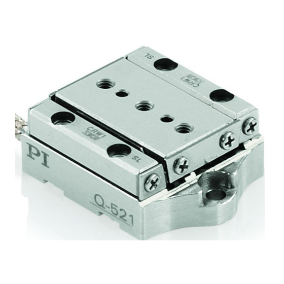
1 nm resolution, 1 N push/pull force, dimensions 21 × 42 × 10 mm (W × L × H), vacuum compatible to 10 Product View Figure 1: Example for models without sensor: Q-521.200 linear stage Motion platform Cable exit for drive connector Connector for drive;... - Page 14 Q-521.xxU Type plate p. 11 Base body Figure 3: Direction of motion of the platform of the Q-521, Q-521.240 used as an example The arrow in the figure above shows the direction of motion on positive commanding. Version: 1.0.1 MP145E...
-
Page 15: Product Labeling
3 Product Description Product Labeling Figure 4: Example for models with sensor: Product labeling and type plate of the Q-521.240 linear stage Position Labeling Description A, C Manufacturer's logo Symbol for the protective earth conductor, marks the protective earth connection of the Q-521 (p. -
Page 16: Scope Of Delivery
3 Product Description Scope of Delivery The Q-521 is delivered with the following components: Item Components Q-521 Linear stage as specified in the order (p. 7) Screw set for mounting the Q-521, consisting of: Q521B0003 2 dowel pins, A2 1.5 m6 x 4 ISO 2338 ... - Page 17 4 dowel pins A2 1.5 m6 x 5 ISO 2338 Q-121.30U 6 machine screws, 1.4567 M2x8 For Q-521.xx0 models only (suitable for use in a vacuum to 10 hPa): Order Description number Vacuum feedthrough (drive and sensor signals), Sub-D 15 (m/f), C-815.VF...
-
Page 18: Suitable Electronics
3.7.1 Linear Encoder (Sensor) Some of the Q-521 models are equipped with an optical linear encoder. For the encoder resolution, refer to the table in the "Specifications" section (p. 49). Optical linear encoders measure the actual position directly (direct metrology). Therefore, errors occurring in the drivetrain such as nonlinearity, backlash or elastic deformation, cannot influence the measurement of the position. -
Page 19: Unpacking
Touching the pins in the Sub-D 15 connection of models equipped with sensor can damage electrostatic-sensitive devices (ESD) of the Q-521. For this reason, these models are supplied with ESD protection. Remove the ESD protection from the connector only when you connect the Q-521 to the controller. INFORMATION When handling the vacuum version of the linear stage, attention must be paid to appropriate cleanliness. -
Page 21: Installation
In this Chapter General Notes on Installation ...................... 17 Mounting the Q-521 on a Surface and Connecting It to a Protective Earth Conductor ....19 Setting Up a Multi-Axis System ....................21 Affixing the Load to the Q-521 ..................... 30 Connecting the Q-521 to the Electronics .................. - Page 22 Install the Q-521 so that the application is not impaired by the dissipated heat. Ensure sufficient ventilation at the place of installation. Make sure that the complete bottom side of the Q-521 is in contact with the surface on which the Q-521 is mounted.
-
Page 23: Mounting The Q-521 On A Surface And Connecting It To A Protective Earth Conductor
NOTICE Warping of the Q-521 due to mounting on uneven surfaces! Mounting the Q-521 on an uneven surface can warp the Q-521. Warping reduces the accuracy. Mount the Q-521 onto an even surface. The recommended flatness of the surface is ≤2 µm. - Page 24 5 Installation INFORMATION The electrical contact of the Q-521 to the protective earth conductor is established via the surface, on which the Q-521 is mounted. The corresponding contact surfaces must be sufficiently conductive. The protective earth conductor is connected to the surface on which the Q-521 is mounted.
-
Page 25: Setting Up A Multi-Axis System
Thread-locking adhesive Mounting the Q-521 on a surface and connecting it to a protective earth conductor Figure 6: Mounting from above, using a Q-521.2xx as an example Option: Aligning the linear stage (view from below) on the surface with 1.5 m6 x 4 locating pins. -
Page 26: General Information On Setting Up A Multi-Axis System
5 Installation Figure 7: Example of an XYZ system: Three Q-521.240 mounted using an adapter plate and an adapter bracket Lower linear stage Q-121.80U adapter plate (for use in a vacuum to 10 hPa) Middle linear stage Q-121.x0U adapter bracket (for use in a vacuum to 10... -
Page 27: Setting Up An Xy System
Only use screws and locating pins of the correct length for the respective holes. INFORMATION Any model of the Q-521 can be used as lower or upper linear stage. Designations in these instructions: Lower linear stage: Forms the basis of the multi-axis system (X axis); is mounted on a ... - Page 28 2 machine screws, M2x4 Suitable tools for tightening the screws Setting up an XY system Figure 8: Example: Mounting a Q-521.240 on a Q-521.240 Lower linear stage 2 locating pins, 1.5 m6 x 4 Q-121.80U adapter plate 2 machine screws, M2x4 2 locating pins, 1.5 m6 x 4...
-
Page 29: Setting Up A Z System With An Adapter Bracket
NOTICE Warping of the Z system with large temperature changes! Large temperature changes can cause warping of the Z system, because the Q-521 and the adapter bracket for the vertical mounting (p. 12) have different thermal expansion properties. Warping reduces the accuracy. - Page 30 Q-521.1xx + Q-121.10U Q-521.2xx + Not possible. The Not possible. The motion platforms of motion platforms of the linear stages the linear stages collide with each collide with each other. other. Q-121.10U Version: 1.0.1 MP145E Q-521 Miniature Linear Stage...
- Page 31 Q-521.2xx + Q-121.20U Q-521.3xx + Not possible. The Not possible. The motion platforms of motion platforms of the linear stages the linear stages collide with each collide with each other. other. Q-121.20U Q-521 Miniature Linear Stage MP145E Version: 1.0.1...
- Page 32 Y axis. (p. 23) Tools and accessories Suitable adapter bracket; for combination options, see "Recommended Z Systems" p. 25. Available as optional accessories (p. 12): − Q-121.10U adapter bracket − Q-121.20U adapter bracket Version: 1.0.1 MP145E Q-521 Miniature Linear Stage...
- Page 33 Suitable tools for tightening the screws Setting up a Z system with an adapter bracket Figure 9: Example: Setting up an XZ system consisting of two Q-521.240 and a Q-121.20U adapter bracket Lower linear stage 4 locating pins, 1.5 m6 x 5 Q-121.20U adapter bracket...
-
Page 34: Affixing The Load To The Q-521
NOTICE Screws and locating pins that are too long! Screws and locating pins that are inserted too deeply damage the Q-521. Pay attention to the depth of the mounting holes (p. 54) in the motion platform. Pay attention to the maximum depth for the insertion of locating pins (p. 54) into the motion platform. - Page 35 You have read and understood the general notes on installation (p. 17). You have properly mounted the linear stage on a surface (p. 19) or on a Q-521 (p. 21). The linear stage is disconnected from the electronics.
-
Page 36: Connecting The Q-521 To The Electronics
3. Check that load is affixed firmly. Connecting the Q-521 to the Electronics The electronics to be used for operating the Q-521 depends on the presence of a sensor (see also "Suitable Electronics" (p. 14)): Models without sensor (Q-521.x0x): E-872 drive electronics ... -
Page 37: Overview: Connecting For Operation At Atmospheric Pressure
5 Installation 5.5.1 Overview: Connecting for Operation at Atmospheric Pressure Figure 10: Possible connection of the Q-521 to suitable electronics for operation at atmospheric pressure Controller Drive electronics Adapter cable Extension cable Adapter for operation outside of the vacuum chamber... -
Page 38: Overview: Connecting For Operation In Vacuum To 10
5 Installation 5.5.2 Overview: Connecting for Operation in Vacuum to 10 Figure 11: Possible connection of the Q-521 to suitable electronics for operation in vacuum Controller Drive electronics Adapter cable Extension cable Vacuum feedthrough for a pressure to 10 Vacuum feedthrough for a pressure to 10 Linear stage Version: 1.0.1... -
Page 39: Connecting The Q-521 To The Electronics
5 Installation Figure 12: Example for installation of the C-815.VF vacuum feedthrough. Left: vacuum side, right: air side Connnector (m) of Q-521 on vacuum side Example of a vacuum feedthrough, part of a vacuum chamber Sealing ring Extension cable C-815.VF vacuum feedthrough... - Page 40 If the E-872.401 drive electronics is used: 7202500060-0015 adapter cable, in the scope of delivery (p. 12) If a Q-521.x0U is to be operated at atmospheric pressure: 5604500041 adapter, in the scope of delivery (p. 12) If the Q-521 is to be operated in a vacuum: ...
-
Page 41: Startup And Operation
If a protective earth conductor is not or not properly connected, dangerous touch voltages can occur on the Q-521 in the case of malfunction or failure of the system. If touch voltages exist, touching the Q-521 can result in minor injuries from electric shock. - Page 42 Reduced lifetime of the piezo actuator due to permanently high voltage! Applying a high static voltage to piezo actuators continuously reduces the lifetime of the piezo ceramic. If the Q-521 is not used for a longer period of time, e.g., several days, switch the electronics off. Version: 1.0.1...
- Page 43 NOTICE Destruction of the piezo actuators by electric flashovers! Using the Q-521 in environments that increase the electrical conductivity can lead to the destruction of the piezo actuators of the drive by electric flashovers. Electric flashovers can be caused by moisture, high humidity, liquids and conductive materials (e.g. metal dust). In addition, electric flashovers can also occur in certain air pressure ranges due to the increased conductivity of the air.
-
Page 44: Starting Up The Q-521
The parameters of the Q-521 can be changed. Changing parameter values can cause undesirable results. Create a backup copy on the PC before changing the parameter settings of the Q-521; see “Saving Parameter Values in a Text File” in the user manual of the electronics. You can then restore the original settings at any time. - Page 45 In the user manual of the controller, the startup is described using the PIMikroMove program. Starting up the Q-521.x0x with E-872 drive electronics 1. Start up the linear stage (see user manual of the drive electronics). The startup comprises the following steps: −...
-
Page 47: Maintenance
General Notes on Maintenance NOTICE Damage due to improper maintenance! Improper maintenance can lead to misalignment and failure of the Q-521. Only loosen screws according to the instructions in this manual. Performing a Maintenance Run The maintenance run must cover the entire travel range. -
Page 49: Troubleshooting
Provide an operating voltage of 48 V. Unfavorable operating Adapt the operating frequency for the step mode frequency for step (for details, see "Starting Up the Q-521" (p. 40) and mode manual of the electronics used). Warped base body ... - Page 50 Contact our customer service department (p. 47). If the problem that occurred with your system is not listed in the table above or cannot be solved as described, contact our customer service department (p. 47). Version: 1.0.1 MP145E Q-521 Miniature Linear Stage...
-
Page 51: Customer Service
9 Customer Service Customer Service For inquiries and orders, contact your PI sales engineer or send us an email (service@pi.de). If you have any questions concerning your system, provide the following information: − Product and serial numbers of all products in the system −... -
Page 53: Technical Data
12 to 32 Integrated Linear Linear Linear Linear Linear Linear sensor encoder encoder encoder encoder encoder encoder Sensor resolution Minimum incremental motion Unidirectional repeatability over entire travel range Bidirectional repeatability over entire travel range Q-521 Miniature Linear Stage MP145E Version: 1.0.1... - Page 54 Q-521.340 / Q-521.x00 / Unit Q-521.14U Q-521.24U Q-521.34U Q-521.x0U Operating 0 to 40 0 to 40 0 to 40 0 to 40 0 to 40 0 to 40 0 to 40 °C temperature range Version: 1.0.1 MP145E Q-521 Miniature Linear Stage...
- Page 55 For operation in a vacuum, we recommend a reduced duty cycle of 20% and a maximum motor push/pull force of 30% compared to a standard environment. The intrinsic mass of the slider plate must be considered accordingly. The specifications were determined on a surface with an evenness of 2 µm. Q-521 Miniature Linear Stage MP145E Version: 1.0.1...
-
Page 56: Maximum Ratings
Frequency Consumption 48 V 20 kHz 10 W 10.1.3 Ambient Conditions and Classifications Pay attention to the following ambient conditions and classifications for the Q-521: Area of application For indoor use only Maximum altitude 2000 m Air pressure Q-521.xx0: 1100 hPa to 10 Q-521.xxU:... -
Page 57: Operating Time
Idle time in s frequency in Hz motion in s 20000 10000 5000 ≤ 1000 For the relevant parameters, see "Starting up the Q-521" (p. 40) and the user manual of the electronics used. Q-521 Miniature Linear Stage MP145E Version: 1.0.1... -
Page 58: Dimensions
10 Technical Data 10.3 Dimensions 10.3.1 Q-521.1xx Dimensions in mm. Note that the decimal places are separated by a comma in the drawings. Figure 13: Q-521.1xx Version: 1.0.1 MP145E Q-521 Miniature Linear Stage... -
Page 59: Q-521.2Xx
10 Technical Data 10.3.2 Q-521.2xx Dimensions in mm. Note that the decimal places are separated by a comma in the drawings. Figure 14: Q-521.2xx Q-521 Miniature Linear Stage MP145E Version: 1.0.1... -
Page 60: Q-521.3Xx
10 Technical Data 10.3.3 Q-521.3xx Dimensions in mm. Note that the decimal places are separated by a comma in the drawings. Figure 15: Q-521.3xx Version: 1.0.1 MP145E Q-521 Miniature Linear Stage... -
Page 61: Q-121.80U Adapter Plate
10 Technical Data 10.3.4 Q-121.80U Adapter Plate Dimensions in mm. Note that the decimal places are separated by a comma in the drawings. Figure 16: Q-121.80U adapter plate Q-521 Miniature Linear Stage MP145E Version: 1.0.1... -
Page 62: Q-121.10U Adapter Bracket
10 Technical Data 10.3.5 Q-121.10U Adapter Bracket Dimensions in mm. Note that the decimal places are separated by a comma in the drawings. Figure 17: Q-121.10U adapter bracket Version: 1.0.1 MP145E Q-521 Miniature Linear Stage... -
Page 63: Q-121.20U Adapter Bracket
10 Technical Data 10.3.6 Q-121.20U Adapter Bracket Dimensions in mm. Note that the decimal places are separated by a comma in the drawings. Figure 18: Q-121.20U adapter bracket Q-521 Miniature Linear Stage MP145E Version: 1.0.1... -
Page 64: Q-121.30U Adapter Bracket
10 Technical Data 10.3.7 Q-121.30U Adapter Bracket Dimensions in mm. Note that the decimal places are separated by a comma in the drawings. Figure 19: Q-121.30U adapter bracket Version: 1.0.1 MP145E Q-521 Miniature Linear Stage... -
Page 65: Vacuum Feedthroughs
62. C-815.VF vacuum feedthrough for 10 Dimensions in mm. Note that the decimal places are separated by a comma in the drawings. Figure 20: C-815.VF vacuum feedthrough Sub-D 15 (m/f) Q-521 Miniature Linear Stage MP145E Version: 1.0.1... - Page 66 Dimensions in mm. Note that the decimal places are separated by a comma in the drawings. Figure 21: Top: View of the opening on the air side; middle: Section of the vacuum chamber as specified by the customer; bottom: View from the vacuum side Version: 1.0.1 MP145E Q-521 Miniature Linear Stage...
- Page 67 C-815.VFU1 vacuum feedthrough for 10 Dimensions in mm. Note that the decimal places are separated by a comma in the drawings. Figure 22: C-815.VFU1 vacuum feedthrough, Sub-D 15 (m/m) Vacuum side Air side Q-521 Miniature Linear Stage MP145E Version: 1.0.1...
- Page 68 C-815.VFU3 vacuum feedthrough for 10 Dimensions in mm. Note that the decimal places are separated by a comma in the drawings. Figure 23: C-815.VFU3 vacuum feedthrough, Sub-D 15 (m/m) Vacuum side Air side Version: 1.0.1 MP145E Q-521 Miniature Linear Stage...
- Page 69 C-815.VFU6 vacuum feedthrough for 10 Dimensions in mm. Note that the decimal places are separated by a comma in the drawings. Figure 24: C-815.VFU6 vacuum feedthrough, Sub-D 15 (m/m) Vacuum side Air side Q-521 Miniature Linear Stage MP145E Version: 1.0.1...
- Page 70 C-815.VFU15 vacuum feedthrough for 10 Dimensions in mm. Note that the decimal places are separated by a comma in the drawings. Figure 25: C-815.VFU15 vacuum feedthrough, Sub-D 15 (m/m) Vacuum side Air side Version: 1.0.1 MP145E Q-521 Miniature Linear Stage...
-
Page 71: Pin Assignment
10 Technical Data 10.4 Pin Assignment 10.4.1 Q-521.xx0 (vacuum compatible to 10 hPa) Connector: Sub-D 15 (m) The Sub-D 15 (m) connector transmits the signals of the drive and, for the models with sensor, in addition the signals of the sensor and of the ID chip. -
Page 72: Q-521.Xxu (Vacuum Compatible To 10 Hpa)
10 Technical Data 10.4.2 Q-521.xxU (vacuum compatible to 10 hPa) Connector: Sub-D 15 (f) The Sub-D 15 (f) connector transmits the signals of the drive and, for the models with sensor, in addition the signals of the sensor and of the ID chip. -
Page 73: C-815.Vf Vacuum Feedthrough
COS - Encoder B (-) Motor (-) Motor signal differential (-) Motor (+) Motor signal differential (+) REF + Reference signal differential (+) SIN + Encoder A (+) COS + Encoder B (+) Q-521 Miniature Linear Stage MP145E Version: 1.0.1... -
Page 74: C-815.Vfux Vacuum Feedthrough
REF - Reference signal differential (-) COS + Encoder B (+) SIN + Encoder A (+) REF + Reference signal differential (+) Motor (+) Motor signal differential (+) Motor (-) Motor signal differential (-) Version: 1.0.1 MP145E Q-521 Miniature Linear Stage... -
Page 75: 5604500041 Adapter
10.4.5 5604500041 Adapter Sub-D 15 (m/m) The adapter is only required if a Q-521.xxU model is to be operated at atmospheric pressure (i.e., without a vacuum feedthrough). Figure 32: Sub-D 15 (m) connector Figure 33: Pin assignment of the 5604500041 adapter... -
Page 77: Old Equipment Disposal
PI miCos equipment made available on the market after 13 August 2005 without charge. Any old PI miCos equipment can be sent free of charge to the following address: PI miCos GmbH Freiburger Strasse 30... -
Page 79: Eu Declaration Of Conformity
12 EU Declaration of Conformity EU Declaration of Conformity For the Q-521, an EU Declaration of Conformity has been issued in accordance with the following European directives: Low Voltage Directive EMC Directive RoHS Directive The applied standards certifying the conformity are listed below.
Need help?
Do you have a question about the Q-521 and is the answer not in the manual?
Questions and answers